EP1831942B1 - Verfahren und vorrichtung zur herstellung eines endgeräts für einen blei-säure-akkumulator - Google Patents
Verfahren und vorrichtung zur herstellung eines endgeräts für einen blei-säure-akkumulator Download PDFInfo
- Publication number
- EP1831942B1 EP1831942B1 EP05817218A EP05817218A EP1831942B1 EP 1831942 B1 EP1831942 B1 EP 1831942B1 EP 05817218 A EP05817218 A EP 05817218A EP 05817218 A EP05817218 A EP 05817218A EP 1831942 B1 EP1831942 B1 EP 1831942B1
- Authority
- EP
- European Patent Office
- Prior art keywords
- slug
- deformation
- shaping
- punch
- die
- Prior art date
- Legal status (The legal status is an assumption and is not a legal conclusion. Google has not performed a legal analysis and makes no representation as to the accuracy of the status listed.)
- Expired - Lifetime
Links
Images



Classifications
-
- B—PERFORMING OPERATIONS; TRANSPORTING
- B21—MECHANICAL METAL-WORKING WITHOUT ESSENTIALLY REMOVING MATERIAL; PUNCHING METAL
- B21J—FORGING; HAMMERING; PRESSING METAL; RIVETING; FORGE FURNACES
- B21J9/00—Forging presses
- B21J9/02—Special design or construction
- B21J9/022—Special design or construction multi-stage forging presses
-
- B—PERFORMING OPERATIONS; TRANSPORTING
- B21—MECHANICAL METAL-WORKING WITHOUT ESSENTIALLY REMOVING MATERIAL; PUNCHING METAL
- B21K—MAKING FORGED OR PRESSED METAL PRODUCTS, e.g. HORSE-SHOES, RIVETS, BOLTS OR WHEELS
- B21K21/00—Making hollow articles not covered by a single preceding sub-group
- B21K21/08—Shaping hollow articles with different cross-section in longitudinal direction, e.g. nozzles, spark-plugs
-
- H—ELECTRICITY
- H01—ELECTRIC ELEMENTS
- H01M—PROCESSES OR MEANS, e.g. BATTERIES, FOR THE DIRECT CONVERSION OF CHEMICAL ENERGY INTO ELECTRICAL ENERGY
- H01M50/00—Constructional details or processes of manufacture of the non-active parts of electrochemical cells other than fuel cells, e.g. hybrid cells
- H01M50/50—Current conducting connections for cells or batteries
- H01M50/543—Terminals
- H01M50/552—Terminals characterised by their shape
-
- H—ELECTRICITY
- H01—ELECTRIC ELEMENTS
- H01M—PROCESSES OR MEANS, e.g. BATTERIES, FOR THE DIRECT CONVERSION OF CHEMICAL ENERGY INTO ELECTRICAL ENERGY
- H01M50/00—Constructional details or processes of manufacture of the non-active parts of electrochemical cells other than fuel cells, e.g. hybrid cells
- H01M50/50—Current conducting connections for cells or batteries
- H01M50/543—Terminals
- H01M50/562—Terminals characterised by the material
-
- H—ELECTRICITY
- H01—ELECTRIC ELEMENTS
- H01M—PROCESSES OR MEANS, e.g. BATTERIES, FOR THE DIRECT CONVERSION OF CHEMICAL ENERGY INTO ELECTRICAL ENERGY
- H01M50/00—Constructional details or processes of manufacture of the non-active parts of electrochemical cells other than fuel cells, e.g. hybrid cells
- H01M50/50—Current conducting connections for cells or batteries
- H01M50/543—Terminals
- H01M50/564—Terminals characterised by their manufacturing process
-
- Y—GENERAL TAGGING OF NEW TECHNOLOGICAL DEVELOPMENTS; GENERAL TAGGING OF CROSS-SECTIONAL TECHNOLOGIES SPANNING OVER SEVERAL SECTIONS OF THE IPC; TECHNICAL SUBJECTS COVERED BY FORMER USPC CROSS-REFERENCE ART COLLECTIONS [XRACs] AND DIGESTS
- Y02—TECHNOLOGIES OR APPLICATIONS FOR MITIGATION OR ADAPTATION AGAINST CLIMATE CHANGE
- Y02E—REDUCTION OF GREENHOUSE GAS [GHG] EMISSIONS, RELATED TO ENERGY GENERATION, TRANSMISSION OR DISTRIBUTION
- Y02E60/00—Enabling technologies; Technologies with a potential or indirect contribution to GHG emissions mitigation
- Y02E60/10—Energy storage using batteries
-
- Y—GENERAL TAGGING OF NEW TECHNOLOGICAL DEVELOPMENTS; GENERAL TAGGING OF CROSS-SECTIONAL TECHNOLOGIES SPANNING OVER SEVERAL SECTIONS OF THE IPC; TECHNICAL SUBJECTS COVERED BY FORMER USPC CROSS-REFERENCE ART COLLECTIONS [XRACs] AND DIGESTS
- Y10—TECHNICAL SUBJECTS COVERED BY FORMER USPC
- Y10T—TECHNICAL SUBJECTS COVERED BY FORMER US CLASSIFICATION
- Y10T29/00—Metal working
- Y10T29/49—Method of mechanical manufacture
- Y10T29/49002—Electrical device making
- Y10T29/49117—Conductor or circuit manufacturing
- Y10T29/49204—Contact or terminal manufacturing
-
- Y—GENERAL TAGGING OF NEW TECHNOLOGICAL DEVELOPMENTS; GENERAL TAGGING OF CROSS-SECTIONAL TECHNOLOGIES SPANNING OVER SEVERAL SECTIONS OF THE IPC; TECHNICAL SUBJECTS COVERED BY FORMER USPC CROSS-REFERENCE ART COLLECTIONS [XRACs] AND DIGESTS
- Y10—TECHNICAL SUBJECTS COVERED BY FORMER USPC
- Y10T—TECHNICAL SUBJECTS COVERED BY FORMER US CLASSIFICATION
- Y10T29/00—Metal working
- Y10T29/49—Method of mechanical manufacture
- Y10T29/49002—Electrical device making
- Y10T29/49117—Conductor or circuit manufacturing
- Y10T29/49204—Contact or terminal manufacturing
- Y10T29/49208—Contact or terminal manufacturing by assembling plural parts
- Y10T29/49218—Contact or terminal manufacturing by assembling plural parts with deforming
-
- Y—GENERAL TAGGING OF NEW TECHNOLOGICAL DEVELOPMENTS; GENERAL TAGGING OF CROSS-SECTIONAL TECHNOLOGIES SPANNING OVER SEVERAL SECTIONS OF THE IPC; TECHNICAL SUBJECTS COVERED BY FORMER USPC CROSS-REFERENCE ART COLLECTIONS [XRACs] AND DIGESTS
- Y10—TECHNICAL SUBJECTS COVERED BY FORMER USPC
- Y10T—TECHNICAL SUBJECTS COVERED BY FORMER US CLASSIFICATION
- Y10T29/00—Metal working
- Y10T29/51—Plural diverse manufacturing apparatus including means for metal shaping or assembling
- Y10T29/5193—Electrical connector or terminal
-
- Y—GENERAL TAGGING OF NEW TECHNOLOGICAL DEVELOPMENTS; GENERAL TAGGING OF CROSS-SECTIONAL TECHNOLOGIES SPANNING OVER SEVERAL SECTIONS OF THE IPC; TECHNICAL SUBJECTS COVERED BY FORMER USPC CROSS-REFERENCE ART COLLECTIONS [XRACs] AND DIGESTS
- Y10—TECHNICAL SUBJECTS COVERED BY FORMER USPC
- Y10T—TECHNICAL SUBJECTS COVERED BY FORMER US CLASSIFICATION
- Y10T29/00—Metal working
- Y10T29/53—Means to assemble or disassemble
- Y10T29/5313—Means to assemble electrical device
- Y10T29/532—Conductor
- Y10T29/53209—Terminal or connector
Definitions
- the present invention relates to a method and an apparatus for the production of a so-called terminal pole or terminal for a lead-acid type accumulator.
- poles for accumulators are made in lead, generally in standardised forms, at least as regards the contact end.
- Poles are known that have a tapered contact part and a base part.
- the latter may be provided with protruding flange, labyrinth, and/or thread-like elements that improve sealing embedding of such base part into the plastic material of the accumulator cover.
- the two parts are either obtained separately and thereafter joined by soldering or by other suitable methods, or as a one, monolithic element.
- a terminal pole should have a compact structure with no pores that may allow leakage or venting of the accumulator content. Pores also promote early corrosion and oxidation of the pole, limiting thus its conductivity.
- the lead is melted and poured into moulds that yield poles of the desired final shape. Proceeding in this way, terminals are obtained however with little resistance to corrosion and prone to causing the seeping of the acid from within the accumulator towards the exterior because of the porosity and the presence of damaging blowholes in the structure of the pole. Thus, efficient seal, between the plastic cover and the pole, is often not obtainable.
- the lead is subjected, in the melted state, to a die-casting process.
- the high-pressure die-casting ensures slight improvements relative to the surface porosity and production velocity.
- the defects typical of the previous method are nevertheless not completely eliminated.
- the pole is manufactured by pressing, starting from a previously calibrated, generally cylindrical lead element, which therefore always needs preliminary processing and equipment to obtain a diameter and length in required tolerance.
- This element is placed in a press mould, which gives a semifinished product having a shape similar to the final one, but which has to be finished with further operations in which end parts of the semifinished product are removed. Satisfactory compactness degree, i.e. lack of pores, is achieved but the method ensures rather low productivity and requires very sturdy devices due to the high working stress involved by the deformation process.
- the aim of the present invention is to provide a method and an apparatus to carry out the method, which are adapted for production, by plastic deformation, of terminal poles for accumulators of a high quality, both as regards the compactness of the finished product and the required dimensional tolerances.
- an important object of the invention is to provide a method and related apparatus with high productivity and capable to cut on the production times and costs, eliminate the necessity of preliminary transformations and reduce to a minimum percentage, preferably in the range of 3-4%, more preferably under 3% and possibly as low as 0% of the total material employed, the material resulting as manufacturing waste, such waste being in any event reusable for reprocessing.
- Another object of the invention is to provide a method and related apparatus that are suitable for manufacturing any type of standardised terminal pole, and even poles with particular shapes, either monolithic or multi-part.
- a further object of the invention is to provide a method and a related apparatus, with light structure, low power consumption and low wear in the active parts, that need little supervision and maintenance operations, suitable to be carried out and, respectively, operated in an environment friendly manner.
- Yet another object of the invention is to provide a method and an apparatus particularly suitable for high operation speed, with no downtimes, and suitable for producing poles with different and selected sizes, irrespective of the dimensions of the starting, raw material.
- the method comprises the steps of: a) shaping, at the shaping station, a slug that has a longitudinal extension along a longitudinal axis thereof such as to provide base and contact parts for the terminal and has a size commensurate with the size of the terminal end piece to be manufactured; b) transferring the slug to said at least one deformation station of the apparatus; c) carrying out a first deformation of the slug for inner and outer shaping of the base part thereof; and d) carrying out at least a second deformation of the slug for performing at least a further inner and outer shaping of the base part thereof, and wherein the steps c) and d) are performed sequentially as progressive deformation steps.
- An apparatus, according to the present invention, for carrying out the method of manufacturing a lead terminal for an accumulator by cold plastic deformation working is set forth in claim 11.
- the apparatus comprises: a shaping station for shaping a slug that has a longitudinal extension along a longitudinal axis thereof such as to provide base and contact parts for the terminal and a size commensurate with the size of the terminal end piece to be manufactured; at least one deformation station adapted to perform progressive and sequential deformations of the slug by way of inner and outer shaping carried out at the contact and base parts thereof; and transfer means for transferring the slug to be worked among said stations.
- an apparatus 1 for manufacturing a lead terminal for an accumulator by cold plastic deformation working comprises in a preferred but not exclusive embodiment thereof, a shaping station 2 for shaping a slug 7, made of a lead material.
- the slug 7 has a longitudinal extension along its longitudinal axis such as to provide a base part 9 and a contact part 8 part for the terminal.
- the size of the slug is set to be commensurate with the size of the terminal end piece to be manufactured.
- the apparatus 1 comprises at least one deformation station 30 preferably two 30, 40, and more preferably four deformation stations 30, 40, 50, 60 or 80 adapted to perform progressive deformations of the slug 7 by way of inner and outer shaping carried out at the contact 8 and base 9 parts the slug 7.
- Transfer means 12 for transferring the slug to be worked among the stations 2, 30, 40, 50, 60 are further provided that may be constituted, by sets of clamps 12a that have the task of transferring the pieces from one station to the next.
- Other transfer means, such as mechanical or hydraulic or pneumatic grasping arms may suitably be provided.
- the shaping station 2 comprises unreeling means 3, for unreeling a lead wire 4 from a wire reel 5.
- Wire drawing and straightening means 6 for drawing and straightening the lead wire 4 that may coincide with the unreeling means and which may be constituted by pairs of rollers 6a, are provided located downstream of the wire reel 5.
- Cutting means 13 to cut the wire 4 at desired lengths equip the shaping station 2.
- the cutting means 13 may be constituted, in a preferred embodiment, by a fixed matrix 13a that has an internal channel 14a in which wire 4 is fed and by a movable matrix 13b that has an inner cavity 14b adapted to receive a pre-set length of wire 4 fed through the fixed matrix.
- the wire length is set in accordance with the desired dimension of the terminal to be shaped.
- the movable matrix 13b is adapted to move with respect to the fixed matrix 13a so as to provide cutting out of a slug 7 that corresponds to the pre-set length of wire 4.
- the cutting means 13 are further fitted with an arresting punch 13c, adapted to arrest advancement of the wire 4 in the movable matrix 13b, upon accommodation therein of the pre-set length of wire 4 and with an expeller punch 13d for expelling the cut out slug 7 from the movable matrix 13b.
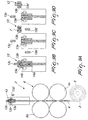
- the shaping station 2 may be provided with a calibration device 100 (see Figures 10A-10B ) that is adapted to calibrate the length of wire cut by the cutting means 13 at a required diameter and overall shape.
- the calibration device 100 allows to use, as a starting material, wire with different diameters, even smaller than the diameter of the slug 7 that has to be subsequently processed at the deformation stations.
- the calibration device 100 comprises a calibration matrix 103 and a hammer punch 101.
- the latter is axially biased by a spring 108 and is movable to press a wire length transferred from the cutting means 13 and supported by clamps 12a.
- the calibration matrix 103 is provided with a calibration matrix punch 102, that is axially movable inside a calibration cavity 109 of the calibration matrix 103 under the pushing action of the wire length, pushed inside the calibration cavity 109 of the matrix 103 by the hammer punch 102.
- An expeller, constituted by a cup-shaped container 105 is arranged movable axially in the calibration cavity 109 and encloses elastic means, constituted by a spring 107.
- a wire length can thus be calibrated in the cavity 109 by virtue of the pressing force exerted thereon by the hammer punch 101 that is opposed by an elastic resistance exerted through the matrix punch 102 under the push of the expeller 105, biased by the spring 107.
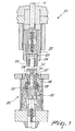
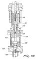
- At least one deformation station 30 is provided for the apparatus ( Figure 1 ) that comprises a fixed part 20 and a movable part 21 aligned along a work axis Y.
- the movable part 20 is movable along the work axis Y.
- the movable part 21 comprises a punch jacket 22, a punch holder 23 enclosed by the punch jacket 22, a hammer punch 24 that is accommodated in the punch holder 23, and a punch insert 25 enclosed by the punch holder 23 and partly enveloping the hammer punch 24.
- the punch holder 23 is slidable on the hammer punch 24.
- the punch jacket 22, punch holder 23, hammer punch 24 and punch insert 25 are mounted in the station 30 coaxial, along the work axis.
- the fixed part 20 comprises a die holder 26 with a segmental die 27 slidably enclosed therein.
- a die punch 28 is movably accommodated in the die holder so as to move with respect to and inside the segmental die 27.
- the die holder 26, segmental die 27 and die punch 28 are mounted in the deformation station coaxial, along the work axis Y.
- the segmental die 27 is substantially shaped as a truncated cone bushing with an outer tapering surface and an inner hole with a shaping die surface.
- the bushing is formed by a plurality of segments 29, for example eight segments, and can slide in the die holder 26 with its tapering outer surface in sliding contact with a complementarily tapered surface of the die holder 26.
- Such bushing 27 slides between a protruding position in which the segments 29 are spread apart in order to receive the base part 9 of a slug 7 to be worked, and an inserted position in which the segments 29 are closed together to form a first half-die adapted to shape by plastic deformation the base part of the slug 7.
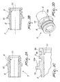
- the first half die in the inserted position of the segmental die 27 is so shaped so as to advantageously form on the base part 9 of the slug, a labyrinth configuration with protruding ridges 9a that may be flat sided and have undercut root portions 9b.
- the die punch 28 has a pushing end 31 that is shaped so as push, upon closure of said segments 29, into the base part of the slug 7 to form therein an inner cavity.
- the punch insert 25 is shaped as a sleeve that has an inside taper adapted to shape a corresponding taper of the contact part 8 of the finished terminal.
- Such inside taper forms a second half-die that cooperates with the first half-die formed by the segmental die 27 for the plastic deformation of the slug 7.
- the fixed part 20 is provided with at least one first bias spring 32, that may be provided as a Belleville washer spring, and at least one second, segment supporting, bias spring 33.
- the springs 32, 33 are mounted in the fixed part 20 under and so as to bias the segmental die 27 in the protruding position in which the segments 29 are spread apart.
- the hammer punch 24 can be actuated to move along the work axis Y and push on the slug so as to overcome the bias exerted by the first and second bias springs 32, 33 and to move the segmental die 27 in the inserted position, whereupon the first and second half-dies form together a shaping die 34 that encloses and shapes the slug 7 at a desired shape upon pressure exerted by the hammer punch 24 on an end of the slug 7.
- the hammer punch 24 can have, in a specific configuration ( Figure 3 or Figure 11 ), an active end 37 provided with a cutting profile adapted to cut out, upon complete formation of the inner cavity, the bottom end portion thereof to form in the slug 7 the through hole 11.
- An inner channel 36 with an outlet opening 39 adapted to allow knockout of the cut bottom end portion 38 can be further provided, in said configuration, in the hammer punch 24.
- the die punch 28 may also be provided with an inner hole 35 connectable to a pressurised air feeding 41 for pushing the cut out bottom end portion 39 through the inner channel 36.
- the apparatus comprises a first 30 and a second 40 deformation stations.
- third 50 and fourth 60 deformation stations are additionally provided.
- the first deformation station 30 is suitable for carrying out at least a first deformation for inner and outer shaping of the base part 9 of the slug 7.
- the second deformation station 40 performs a second deformation for further inner and outer shaping of the base part 9 of the slug 7.
- an outer shaping of the contact part 8 of the slug 7 may be performed at the second station 40.
- a first outer shaping of the contact part 8 may also be carried out at the first deformation station 30.
- the third deformation station 50 is suitably fitted for a third deformation for inner and outer shaping of the contact part 8 and for a further inner shaping of the base part 9 of the slug 7.
- the inner cavity 11 is formed in the slug 7 that extends longitudinally, axially therein, through the base part 9 and the contact part 8, for substantially all the longitudinal extension of the contact part 8 but for a bottom end portion 38 that plugs the end part of the slug 7.
- the fourth deformation station 60 is suitable to provide the perforation of the inner cavity 11 of the slug 7, by way of the hammer punch 24, fitted with the active end 37, to form the through hole, also designated with 11 in the Figures, by the cutting out of the plugging, bottom end portion 38.
- the shaping 2 and deformation stations 30, 40, 50, 60 are all mounted on a frame 70 enclosing movement actuation means 71, that may be of the fluid actuated type, for actuating the movable part 20 and the die punch 28.
- a deformation station 80 may additionally be provided, or to replace station 60.
- the station 80 is provided with a segmental die 27 and with a hammer punch 24 that has an active end 37 with cutting profile to form in the slug 7 the through hole 11.
- the slug 7 is pre-formed at the previous deformation stations with the ridges 9a that have a crown profile with cusps 9c.
- the segments 29 press onto the cusps 9c to flatten them while a material migration occurs that give the ridges the mushroom form, with undercut root portion 9b, as shown in Figure 2B and 12B .
- a control unit CU provided with sensing means for sensing hydraulic and pneumatic pressure, temperature and position parameters of the various parts of the apparatus and to provide indicative signals, with storing and processing means to store and process the signals received from the sensing means, and also with suitable firmware or software, controls operation of the apparatus.
- the half-dies formed by the segments 29 and punch insert 25, on closing, permit the deformation of the slug metal and achieving of the desired shape, while on opening permit the extraction of the slug metal already deformed and insertion of the slug metal still to be deformed.
- the apparatus is supplied with a Pb continuous wire 4, wound on the metal reels 5 (coils).
- the reels 5 are mounted on the unreeling device 3, that may be provided at the shaping station 2 as a part of the apparatus/machine, idle or powered according to the weight of the reel, with the unwinding axis preferably horizontal.
- the lead wire 4 is then introduced into the first (shaping) station 2 of the machine for drawing-strengthening.
- rollers or runners 6a have the task of advancing "in jerks" the wire to the cutting means 13 at lengths of the wire slug 7 adjustable as a function of the size of the end piece that is desired to be produced.
- the wire is first of all introduced into the fixed (knife) matrix 13a formed by a block of steel in which a hard metal insert is housed with the characteristic of being interchangeable and to have, from time to time, a cylindrical cavity of a slightly larger diameter than the diameter of the Pb wire that is being used.
- a movable (knife) matrix 13b In axis with the fixed matrix 13a a movable (knife) matrix 13b is provided that has the similar geometric and constructive characteristics as the fixed matrix 13a, plus the possibility of being able to rotate around an axis parallel to that of the cylindrical cavity of the fixed matrix or anyway to move in an offset position with respect thereto. This movement is what permits the cutting of the wire slug 7 introduced into the movable matrix 13b.
- the expeller punch 13d effects then ejection of the Pb cut-off from the movable matrix.
- the cut-off is simultaneously collected by the clamp 12a provided therefor.
- the clamp 12a that has collected the cut-off from the shaping station 2 moves the slug 7 to the first deformation station 30 where the base part of the terminal pole, advantageously with a labyrinth, is formed.
- the configuration of the deformation stations renders the apparatus particularly adapted to easily form labyrinth configurations with undercuts that are very difficult if not impossible to obtain with the prior art devices.
- the cut wire length can be previously calibrated at the calibration device 100.
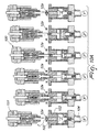
- Figure 4 shows the pressing sequence of the slug 7 at four different deformation stations 30, 40, 50, 60.
- the Pb cut-off slug is held in position along the same axis of the matrix by the clamp 12a while the movable part of the machine moves towards the fixed part.
- segmental die 27 is opened by the action of the springs 32, 33.
- the entire Pb slug undergoes deformation that leads to it occupying the free volume provided inside the segmental die 27.
- the opening and ejection step of the deformed slug can thereafter commence.
- the clamp 12a intervenes again to collect the deformed slug in correct position.
- clamp 12a that supported the slug in the initial insertion step, widening immediately afterwards to permit the closure of the machine, but the clamp 12a of the following operation (deformation station) that, as soon as the opening of the machine has commenced, is transferred to this operation to collect the deformed slug and take it to the following station.
- the method of manufacturing a lead terminal for an accumulator by plastic deformation on the cold-working apparatus 1 that has a shaping station 2 and at least one deformation station 30, 40, 50, 60, 80 comprises the steps of: a) shaping, at the shaping station 2 of the apparatus 1, the slug 7 that has a longitudinal extension along a longitudinal axis Y thereof such as to provide base 9 and contact 8 parts for the terminal and has a size commensurated to the size of the terminal end piece to be manufactured; b) transferring the slug 7 to said at least one deformation station of the apparatus; c) carrying out a first deformation of the slug 7 for inner and outer shaping of the base part thereof; and d) carrying out at least a second deformation of the slug 7 for further inner and outer shaping of the base part 9 thereof.
- the steps c), d) are performed sequentially as progressive deformation steps.
- a further step e) for carrying out a third deformation of the slug 7 for inner and outer shaping of the contact part 8 and of for a further inner shaping of the base part 9 thereof is further carried out.
- progressive deformation is intended to mean that the plastic deformation of the slug up to its final finished shape suitable for a terminal pole, is made gradually, in successive deformation steps that prevent high stress to be exerted on the apparatus parts and at the same time are prone to be carried out with high velocity, and in a coordinated manner.
- deformation steps are performed on the same slug, in sequence, at different deformation stations suitably equipped, or at the same deformation station, but anyway, at discrete moments that allow to contain the deformation forces.
- Step c) comprises forming on an outer surface region of the base part 9 of the slug the labyrinth configuration constituted by ridges that protrude from said outer surface of the base parts, that may have undercut, root portions, and forming of the cavity that has an extension inside the base part laying along said longitudinal axis of the slug;
- step d) comprises forming at an outer region of the slug, between the base and contact parts, of a crown 10 that is constituted by a protruding flange that has an edge bearing a plurality of notches 10a, and increasing the extension of the cavity along the longitudinal axis of the slug.
- Step e) comprises forming the outer surface of the contact part so as to have a truncated cone configuration with the larger base at the crown 10 and increasing still the extension of the cavity along the longitudinal axis of the slug so as to also extend inside the contact part for substantially all the longitudinal extension thereof but for a bottom end portion.
- the additional step f) is carried out that consists in cutting off the bottom end portion of the cavity so as to form the through hole 11 inside the slug, as illustrated in Figure 3 and last operation phase of Figure 4 .
- the apparatus for carrying out the invention may be provided, in a possible embodiment thereof, with only one deformation station and in which the working parts may be automatically exchangeable in accordance with the deformation step that has to be performed.
- the deformation steps are carried out at separate deformation stations 30, 40, 50, 60, 80 of the apparatus by providing, between each two consecutive said deformation steps, a respective additional transferring step.
- the additional step f) comprises a knocking out of the cut bottom end portion 38 of the slug 7.
- the apparatus is adapted and may be operated so that the deformation steps are carried out at the deformation stations 30, 40, 50, 60, 80 simultaneously.
- each deformation step is carried out at a respective deformation station on a different slug that is in a different deformation phase of progressive deformation obtained following to a previous deformation step, the transferring steps being coordinated with the progressive deformation steps.
Landscapes
- Chemical & Material Sciences (AREA)
- Chemical Kinetics & Catalysis (AREA)
- Electrochemistry (AREA)
- General Chemical & Material Sciences (AREA)
- Engineering & Computer Science (AREA)
- Mechanical Engineering (AREA)
- Manufacturing & Machinery (AREA)
- Forging (AREA)
- Connection Of Batteries Or Terminals (AREA)
- Electrical Discharge Machining, Electrochemical Machining, And Combined Machining (AREA)
Claims (24)
- Verfahren zum Herstellen eines Bleianschlusses für einen Akkumulator durch plastische Verformung in einer Kaltbearbeitungsvorrichtung, die eine Formungsstation und zumindest eine Verformungsstation aufweist, umfassend die Schritte:a) Formung eines Rohlings in der Formungsstation, der eine Längserstreckung entlang einer Längsachse desselben aufweist, um Basis- und Kontaktteile für den Anschluß bereitzustellen, und eine Größe hat, die der Größe des herzustellenden Anschlußendteiles entspricht;b) Transferieren des Rohlings auf zumindest eine Verformungsstation der Vorrichtung;c) Ausführen einer ersten Verformung des Rohlings zur inneren und äußeren Formung des Basisteiles desselben; undd) Ausführen einer zweiten Verformung des Rohlings zum Ausbilden zumindest einer weiteren inneren und äußeren Formung des Basisteiles desselben;
und wobei die Schritte c) und d) nacheinander als fortschreitende Verformungsschritte ausgeführt werden, und das Formen eines Außenflächenbereiches des Basisteiles des Rohlings mit einer labyrinthförmigen Konfiguration, welche durch von der Außenfläche des Basisteiles abstehende Rippen gebildet ist, sowie die Formung eines Hohlraumes umfassen, der eine Erstreckung innerhalb des Basisteiles entlang der Längsachse des Rohlings hat, wobei die Rippen mit einem Kronenprofil mit Zacken geformt werden, die weiter gepreßt werden, um die Rippen mit den hinterschnittenen Wurzelabschnitten zu versehen. - Verfahren nach Anspruch 1, das ferner den Schritt e) zum Ausführen einer dritten Verformung des Rohlings zum inneren und äußeren Formen des Kontaktteiles und weiters zum inneren Formen des Basisteiles desselben umfaßt.
- Verfahren nach Anspruch 1, bei welchem die zweite Rohlingsverformung im Schritt d) ferner das äußere Formen des Rohlings zum Gestalten des Kontaktteiles des Anschlusses umfaßt.
- Verfahren nach einem der Ansprüche 1 bis 3, wobei der Schritt d) das Formen einer Krone in einem Außenbereich des Rohlings zwischen den Basis- und den Kontaktteilen umfaßt, wobei die Krone durch einen vorragenden Flansch gebildet ist, der einen eine Vielzahl von Kerben aufweisenden Rand hat, und Vergrößern der Hohlraumerstreckung entlang der Längsachse des Rohlings.
- Verfahren nach Anspruch 1 oder 4, bei welchem der Schritt e) das Formen der Außenfläche des Kontaktteiles umfaßt, um diesem eine kegelstumpfförmige Gestalt zu verleihen, wobei die größere Basis mit dem Basisteil verbunden ist und die Erstreckung des Hohlraumes entlang der Längsachse des Rohlings vergrößert wird, um sich von dem Basisteil innerhalb des Kontaktteiles im wesentlichen über die gesamte Längserstreckung desselben mit Ausnahme eines unteren Endabschnittes zu erstrecken.
- Verfahren nach Anspruch 3, das ferner den zusätzlichen Schritt f) umfaßt, der darin besteht, daß der untere Endabschnitt des Hohlraumes abgeschnitten wird, um ein Durchtrittsloch innerhalb des Rohlings zu bilden.
- Verfahren nach einem vorhergehenden Ansprüche, bei welchem die Verformungsschritte in separaten Verformungsstationen der Vorrichtung ausgeführt werden, wobei zwischen je zwei aufeinanderfolgenden Verformungsschritten ein zusätzlicher Transferschritt vorgesehen ist.
- Verfahren nach Anspruch 4 oder 5, abhängig von Anspruch 7, wobei der zusätzliche Schritt f) das Herausschlagen des unteren Endabschnittes des Rohlings umfaßt.
- Verfahren nach Anspruch 7, bei welchem die Verformungsschritte in den Verformungsstationen der Vorrichtung gleichzeitig ausgeführt werden, wobei jeder Verformungsschritt in einer entsprechenden Verformungsstation an einem unterschiedlichen Rohling ausgeübt wird, der sich in einer unterschiedlichen Verformungsphase der fortschreitenden Verformung befindet, die nach dem vorhergehenden Verformungsschritt erhalten wird, wobei die Transferschritte mit den fortschreitenden Verformungsschritten koordiniert werden.
- Verfahren nach einem der vorhergehenden Ansprüche, bei welchem der Formungsschritt a) eine Kalibrierung des Rohlings umfaßt.
- Vorrichtung zum Herstellen eines Bleianschlusses eines Akkumulators durch plastische Kaltverformung, dadurch gekennzeichnet, daß sie aufweist: eine Formungsstation (2) zum Formen eines Rohlings (7), der eine Längserstreckung entlang einer Längsachse desselben aufweist, um Basis- (9) und Kontaktteile (8) für den Anschluß zu schaffen, und eine Größe, die der Größe des herzustellenden Anschlußendteiles entspricht; zumindest eine Verformungsstation (30, 40, 50, 60, 80), die so ausgebildet ist, daß sie fortschreitende und aufeinanderfolgende Verformungen des Rohlings durch innere und äußere Formung an den Kontakt- (8) und Basisteilen (9) desselben ausführt; und Transfermittel (12) zum Transferieren des zu bearbeitenden Rohlings zwischen den Stationen (2, 30, 40, 50, 60, 80), wobei die zumindest eine Verformungsstation (30, 40, 50, 60, 80) dazu bestimmt ist, einen Außenflächenbereich des Basisteiles (9) des Rohlings (7) mit einer labyrinthförmigen Konfiguration zu versehen, die durch Rippen (9a) gebildet ist, welche vcn der Außenfläche des Basisteiles (9) abstehen und ein Kronenprofil mit Zacken (9c) haben;
wobei die zumindest eine Verformungsstation (30, 40, 50, 60, 80) einen feststehenden Teil (20) und einen bewegbaren Teil (21) aufweist, die entlang einer Arbeitsachse (Y) ausgerichtet sind, wobei der bewegbare Teil entlang dieser Arbeitsachse bewegbar ist; und
wobei der feststehende Teil (20) umfaßt: einen Formungskörper-Halter (26); einen segmentförmigen Formungskörper (27), der in dem Halter (26) gleitverschieblich eingebaut ist; und einen Formungsstempel (28), der in dem Formungkörper-Halter (26) bewegbar aufgenommen ist, um sich relativ und innerhalb des segmentförmigen Formungskörpers (27) zu bewegen, wobei der Halter (26), der segmentförmige Formungskörper (27) und der Formungsstempel (28) koaxial entlang der Arbeitsachse (Y) montiert sind, wobei der segmentförmige Formungskörper (27) als Büchse geformt ist, die durch eine Vielzahl von Segmenten (29) gebildet ist, welche dazu geeignet sind, auf die Zacken (9c) der Rippen (9a) zu pressen, um die Rippen (9a) mit hinterschnittenen Wurzelabschnitten (9b) auszubilden. - Vorrichtung nach Anspruch 11, bei welcher die Formungsstation (2) Abrollmittel (3) zum Abrollen eines Bleidrahtes (4) von einer Drahttrommel (5), Drahtzieh- und Richtmittel (6) zum Ziehen und Richten des Drahtes, und Schneidmittel (13) zum Schneiden des Drahtes in gewünschte Längen umfaßt.
- Vorrichtung nach Anspruch 12, bei welcher die Schneidmittel (13) umfassen: ein feststehendes Gesenk (13a) zum Hindurchführen des Drahtes; ein bewegbares Gesenk (13b) zur Aufnahme einer voreingestellten Länge des Drahtes (4), der durch das feststehende Gesenk (13a) geführt wird, wobei das bewegbare Gesenk (13b) so ausgebildet ist, daß es sich relativ zum feststehenden Gesenk (13a) bewegt, um ein Ausschneiden eines Rohlings (7) mit einer Länge, welche der voreingestellten Länge des Drahtes (4) entspricht, vorzunehmen; einen Arretierstempel (13c), der so ausgebildet ist, daß er den Vorschub des Drahtes (4) in dem bewegbaren Gesenk (13b) nach Aufnahme der voreingestellten Länge des Drahtes (4) stillsetzt; und einen Ausstoßstempel (13d) zum Ausstoßen des ausgeschnittenen Rohlings (7) aus dem bewegbaren Gesenk (13b).
- Vorrichtung nach Anspruch 12, bei welcher die Formungsstation (2) zusätzlich eine Kalibriervorrichtung (100) zum Kalibrieren einer ausgeschnittenen Drahtlänge aufweist.
- Vorrichtung nach Anspruch 11, bei welcher der bewegbare Teil (21) umfaßt: eine Stempelaufnahme (22); einen Stempelhalter (23), der von der Stempelaufnahme (22) umschlossen ist; einen Hammerstempel (24), der in dem Stempelhalter (23) aufgenommen ist; und einen Stempeleinsatz (25), der von dem Stempelhalter (23) umgeben ist und teilweise den Hammerstempel (24) umgibt, so daß dieser gleitverschieblich ist, wobei die Stempelaufnahme, der Stempelhalter, der Hammerstempel und der Stempeleinsatz entlang der Arbeitsachse (Y) koaxial montiert sind.
- Vorrichtung nach einem der Ansprüche 11-15, dadurch gekennzeichnet, daß sie eine erste (30) und eine zweite (40) Verformungsstation und vorzugsweise eine dritte (50) und eine vierte (60) Verformungsstation aufweist.
- Vorrichtung nach Anspruch 16, bei welcher die Verformungsstationen gebildet sind durch: eine erste Verformungsstation (30), in welcher die erste Verformung zum inneren und äußeren Formen des Basisteiles des Rohlings (7) ausgeführt wird; eine zweite Verformungsstation (40), in welcher die zweite Verformung zum weiteren inneren und äußeren Formen des Basisteiles des Rohlings (7) ausgeführt wird, und gegebenenfalls eine äußere Formung des Kontaktteiles (8) des Rohlings (7) ausgeführt wird, eine dritte Verformungsstation (50), in welcher eine dritte Verformung zum inneren und äußeren Formen des Kontaktteiles (8) und zum weiteren inneren Formen des Basisteiles (9) des Rohlings (7) ausgeführt wird, und in welcher ein innerer Hohlraum geformt wird, der sich in der Längsrichtung des Rohlings (7) durch den Basisteil (9) und den Kontaktteil über im wesentlichen die gesamte Längserstreckung des Kontaktteiles (8) mit Ausnahme eines unteren Endabschnittes (38) desselben erstreckt; und eine vierte Verformungsstation (60), in welcher schließlich ein Durchtrittsloch (11) im Inneren des Rohlings (7) durch Abschneiden des unteren Endabschnittes gebildet wird.
- Vorrichtung nach Anspruch 17, bei welcher die erste Verformungsstation (30) mit dem segmentförmigen Formungskörper (27) ausgestattet ist, der im wesentlichen als Kegelstumpfbüchse mit einer äußeren verjüngten Oberfläche und einem inneren Loch mit einer Formungsfläche geformt ist, wobei die Büchse aus einer Vielzahl dieser Segmente (29) gebildet und im Halter (26) gleitverschieblich angeordnet ist, wobei ihre verjüngte Außenfläche in Gleitkontakt mit
einer komplementär verjüngten Fläche des Formungskörper-Halters (26) zwischen einer vorragenden Position, in welcher die Segmente auseinandergespreizt sind, um den Basisteil (9) eines zu bearbeitenden Rohlings (7) aufzunehmen, und einer Einsetzposition ist, in welcher die Segmente geschlossen sind, um einen ersten Halbstempel zu bilden, der befähigt ist, den Basisteil des Rohlings (7) durch plastische Verformung zu formen. - Vorrichtung nach Anspruch 18, bei welcher der Formungsstempel (28) ein Druckende (31) aufweist, das so geformt ist, daß es beim Schließen der Segmente (29) in den Basisteil des Rohlings (7) drückt, um einen inneren Hohlraum zu bilden.
- Vorrichtung nach einem der Ansprüche 15 bis 19, dadurch gekennzeichnet, daß der Stempeleinsatz (25) als Hülse geformt ist, die eine innere Verjüngung aufweist, die befähigt ist, eine entsprechende Verjüngung des Kontaktteiles (8) des fertigen Anschlusses zu formen, wobei die innere Verjüngung, welche einen zweiten Halbstempel bildet, der mit dem ersten Halbstempel zusammenwirkt, der von dem segmentförmigen Formungskörper (27) zur plastischen Verformung des Rohlings (7) gebildet ist.
- vorrichtung nach einem der Ansprüche 17 bis 20, bei welcher der feststehende Teil (20) mit zumindest einer ersten Vorspannfeder (32) und zumindest einer zweiten Vorspannfeder (33) versehen ist, die so montiert sind, daß sie den segmentförmigen Formungskörper (27) in die vorragende Position verspannen, in welcher die Segmente (29) auseinandergespreizt sind.
- Vorrichtung nach Anspruch 21, bei welcher der Hammerstempel (24) so betätigbar ist, daß er sich entlang der Arbeitsachse (Y) bewegt, um den Rohling mit Druck zu beaufschlagen, um die von den ersten und zweiten Vorspannfedern (32, 33) ausgeübte Vorspannung zu überwinden und den segmentförmigen Formungskörper (27) in die Einsatzposition zu bewegen, wobei der erste und zweite Halbstempel gemeinsam einen Formungsstempel (34) bilden, der befähigt ist, den Rohling (7) aufzunehmen und mit Hilfe des vom Hammerstempel (24) ausgeübten Druckes auf das Rohlingsende in eine gewünschte Gestalt zu formen.
- Vorrichtung nach Anspruch 15 oder 22, dadurch gekennzeichnet, daß der Hammerstempel (24) ein aktives Ende (37) hat, das mit einem Schneidprofil versehen ist, welches so ausgebildet ist, daß es den unteren Endabschnitt des Hohlraumes ausschneidet, um in dem Rohling (7) das Durchtrittsloch (11) und einen inneren Kanal (36) mit einer Auslaßöffnung (39) zu bilden, die befähigt ist, ein Herausschlagen des ausgeschnittenen unteren Endabschnitts (38) zu gestatten, und daß der Formungsstempel (28) mit einem inneren Loch (35) versehen ist, welches mit einer Druckluftzufuhr (41) verbindbar ist, um den ausgeschnittenen unteren Endabschnitt (38) durch den inneren Kanal (36) zu drücken.
- Vorrichtung nach Anspruch 12 oder 16, dadurch gekennzeichnet, daß die Formungs- und Verformungsstationen (2, 30, 40, 50, 60, 80) auf einem Rahmen (70) montiert sind, der mit Hewegungsbetätigungsmitteln (71) zum Betätigen der bewegbaren Teile (21) und des Formungsstempels (28) ausgestattet ist.
Priority Applications (2)
| Application Number | Priority Date | Filing Date | Title |
|---|---|---|---|
| SI200531275T SI1831942T1 (sl) | 2004-11-17 | 2005-11-14 | Postopek in naprava za izdelavo priključka za svinčev akumulator |
| PL05817218T PL1831942T3 (pl) | 2004-11-17 | 2005-11-14 | Sposób i urządzenie do wytwarzania czopu dla akumulatora typu ołowiowo-kwasowego |
Applications Claiming Priority (2)
| Application Number | Priority Date | Filing Date | Title |
|---|---|---|---|
| GB0425342A GB2420300B (en) | 2004-11-17 | 2004-11-17 | Method and apparatus for the manufacture of a terminal for a lead-acid type accumulator and a terminal manufactured therewith |
| PCT/EP2005/012176 WO2006053698A1 (en) | 2004-11-17 | 2005-11-14 | Method and apparatus for the manufacture of a terminal for a lead-acid type accumulator and a terminal manufactured therewith |
Publications (2)
| Publication Number | Publication Date |
|---|---|
| EP1831942A1 EP1831942A1 (de) | 2007-09-12 |
| EP1831942B1 true EP1831942B1 (de) | 2011-01-26 |
Family
ID=33548432
Family Applications (1)
| Application Number | Title | Priority Date | Filing Date |
|---|---|---|---|
| EP05817218A Expired - Lifetime EP1831942B1 (de) | 2004-11-17 | 2005-11-14 | Verfahren und vorrichtung zur herstellung eines endgeräts für einen blei-säure-akkumulator |
Country Status (16)
| Country | Link |
|---|---|
| US (1) | US7946033B2 (de) |
| EP (1) | EP1831942B1 (de) |
| JP (1) | JP5143564B2 (de) |
| KR (1) | KR20070085546A (de) |
| CN (1) | CN101057352B (de) |
| AT (1) | ATE497261T1 (de) |
| CA (1) | CA2584533C (de) |
| DE (1) | DE602005026171D1 (de) |
| ES (1) | ES2380140T3 (de) |
| GB (1) | GB2420300B (de) |
| IL (1) | IL183270A (de) |
| PL (1) | PL1831942T3 (de) |
| RU (1) | RU2374721C2 (de) |
| SI (1) | SI1831942T1 (de) |
| UA (1) | UA91990C2 (de) |
| WO (1) | WO2006053698A1 (de) |
Families Citing this family (23)
| Publication number | Priority date | Publication date | Assignee | Title |
|---|---|---|---|---|
| GB2420300B (en) * | 2004-11-17 | 2007-01-10 | Accuma Plastics Ltd | Method and apparatus for the manufacture of a terminal for a lead-acid type accumulator and a terminal manufactured therewith |
| JP5299283B2 (ja) | 2007-11-19 | 2013-09-25 | 富士通株式会社 | 情報処理装置及び情報処理システム並びにそれらの制御方法 |
| DE102008038185B3 (de) * | 2008-08-19 | 2010-01-28 | Sieber Forming Solutions Gmbh | Verfahren und Vorrichtung zur Herstellung von Befestigungs- oder Verbindungsmitteln mit radialen Außenkonturen, insbesondere Schrauben oder Gewindebolzen |
| KR20110084215A (ko) * | 2008-10-03 | 2011-07-21 | 지베르 포밍 솔류션 게엠바하 | 중공형 금속 소재 상의 외부 쓰레드의 비절삭 제조방법 및 장치 |
| CN101521270B (zh) * | 2008-12-15 | 2011-02-09 | 英明精密机件(苏州)有限公司 | 铅端子的成型方法 |
| US9847522B2 (en) | 2010-03-09 | 2017-12-19 | Johnson Controls Autobatterie Gmbh & Co. Kgaa | Connecting pole for a rechargeable battery and rechargeable battery housing |
| JP5547045B2 (ja) * | 2010-03-30 | 2014-07-09 | 古河電池株式会社 | ブッシングの製造方法、及び、ブッシングの鋳型 |
| KR101155583B1 (ko) * | 2010-07-14 | 2012-06-19 | 세방전지(주) | 배터리 터미널 시스템 및 그 제조방법 |
| WO2012118306A2 (ko) * | 2011-02-28 | 2012-09-07 | Kang Tae In | 배터리 터미널 플레이트의 제조장치 및 제조방법 |
| KR101323642B1 (ko) | 2012-02-16 | 2013-11-05 | 김용수 | 배터리 터미널 플레이트의 제조장치 및 제조방법 |
| DE102011050182A1 (de) * | 2011-05-06 | 2012-11-08 | Röhr + Stolberg Gmbh | Verfahren zur Herstellung eines Batteriepols |
| DE202011103277U1 (de) * | 2011-07-11 | 2011-11-21 | Vb Autobatterie Gmbh & Co. Kgaa | Anschlusspol für einen Akkumulator, Akkumulatorgehäuse und Maschine zur Herstellung eines Anschlusspols |
| KR101240459B1 (ko) * | 2012-01-31 | 2013-03-11 | 김용수 | 배터리 터미널 플레이트의 제조방법 |
| KR101381893B1 (ko) * | 2012-06-01 | 2014-04-14 | 김용수 | 가공물 성형장치 |
| MX2013003133A (es) * | 2012-12-06 | 2014-06-20 | Jose Antonio Kurt Mayrl Y Sanchez Juarez | Aparato y metodo para la fabricacion de terminales para baterias. |
| KR101450789B1 (ko) * | 2013-08-29 | 2014-10-15 | 주식회사 코일마스터 | 공심형 인덕터 몰드코일의 제조방법 |
| KR101394342B1 (ko) * | 2014-02-24 | 2014-05-13 | 신영식 | 배터리 단자의 융착 성형기계 |
| DE102014003726A1 (de) * | 2014-03-18 | 2015-09-24 | Gkn Sinter Metals Engineering Gmbh | Presse zum Herstellen maßhaltiger Grünlinge und Verfahren zum Herstellen |
| US9724748B2 (en) * | 2014-08-11 | 2017-08-08 | Arvinmeritor Technology, Llc | System and method of making a forged part |
| USD767490S1 (en) | 2015-01-07 | 2016-09-27 | Johnson Controls Technology Company | Battery bushing |
| ES2654807T3 (es) * | 2015-08-20 | 2018-02-15 | Wegmann Automotive Gmbh & Co. Kg | Terminal de batería con protección antitorsión interna |
| US10391545B2 (en) * | 2017-03-17 | 2019-08-27 | The Boeing Company | Self-aligning riveting method |
| KR102265185B1 (ko) * | 2019-09-18 | 2021-06-15 | 한국앤컴퍼니 주식회사 | 전해액 누출방지구조를 구성한 자동차용 배터리 단자 제조 방법 및 이에 의해 제조된 배터리 단자 |
Family Cites Families (19)
| Publication number | Priority date | Publication date | Assignee | Title |
|---|---|---|---|---|
| JPH0347311U (de) * | 1989-09-09 | 1991-05-01 | ||
| US4945749A (en) * | 1989-10-30 | 1990-08-07 | General Motors Corporation | Cold forming dies and cold forming process |
| US5077892A (en) * | 1990-03-21 | 1992-01-07 | Nugent Robert R | Method for the manufacture of structurally homogeneous flash-free lead battery terminals |
| JPH057974A (ja) * | 1991-06-30 | 1993-01-19 | Obara Kinzoku Kogyo Kk | 電池極柱用ブツシング成形装置 |
| JPH05169183A (ja) * | 1991-12-16 | 1993-07-09 | Obara Kinzoku Kogyo Kk | 電池極柱用ブッシング鍛造装置及び鍛造ヘッダー |
| US5373720A (en) * | 1992-09-03 | 1994-12-20 | Water Gremlin Company | Method of making battery terminal with necked flange |
| US5296317A (en) * | 1992-09-03 | 1994-03-22 | Water Gremlin Co. | High torque battery terminal and method of making same |
| US5791183A (en) * | 1995-05-17 | 1998-08-11 | Tulip Corporation | Apparatus and method for cold forming a ring on a lead alloy battery terminal including an anti-torque structure |
| US5632173A (en) | 1995-05-17 | 1997-05-27 | Tulip Corporation | Apparatus and method for cold forming a ring on a lead alloy battery terminal |
| US5655400A (en) | 1995-06-02 | 1997-08-12 | Tulip Corporation | Progressive die apparatus and method for making a lead alloy battery terminal |
| JPH10193029A (ja) * | 1997-01-10 | 1998-07-28 | Sintokogio Ltd | 鉛陽陰極端子の製造方法及びその装置 |
| JP2892638B1 (ja) * | 1997-11-25 | 1999-05-17 | 広島工業株式会社 | 蓄電池槽用鉛端子の閉塞鍛造装置及び鍛造方法 |
| IT1303739B1 (it) * | 1998-11-11 | 2001-02-23 | Fata Automation | Dispositivo riformatore per elettrodi di saldatura |
| US6688148B1 (en) * | 2001-01-26 | 2004-02-10 | Defiance Precision Products, Inc. | Manufacturing process for making engine components of high carbon content steel using cold forming techniques |
| US6644084B1 (en) | 2001-06-14 | 2003-11-11 | Tulip Corporation | Method and apparatus for manufacturing a battery terminal with undercut rings |
| US6803146B2 (en) * | 2001-07-19 | 2004-10-12 | Delphi Technologies, Inc. | Battery terminal and method for making the same |
| US7338539B2 (en) | 2004-01-02 | 2008-03-04 | Water Gremlin Company | Die cast battery terminal and a method of making |
| US7070441B1 (en) | 2004-03-15 | 2006-07-04 | Tulip Corporation | Acid seal |
| GB2420300B (en) * | 2004-11-17 | 2007-01-10 | Accuma Plastics Ltd | Method and apparatus for the manufacture of a terminal for a lead-acid type accumulator and a terminal manufactured therewith |
-
2004
- 2004-11-17 GB GB0425342A patent/GB2420300B/en not_active Expired - Fee Related
-
2005
- 2005-11-14 JP JP2007541764A patent/JP5143564B2/ja not_active Expired - Fee Related
- 2005-11-14 RU RU2007122473/09A patent/RU2374721C2/ru not_active IP Right Cessation
- 2005-11-14 CA CA2584533A patent/CA2584533C/en not_active Expired - Fee Related
- 2005-11-14 SI SI200531275T patent/SI1831942T1/sl unknown
- 2005-11-14 CN CN2005800389038A patent/CN101057352B/zh not_active Expired - Fee Related
- 2005-11-14 PL PL05817218T patent/PL1831942T3/pl unknown
- 2005-11-14 UA UAA200706708A patent/UA91990C2/ru unknown
- 2005-11-14 DE DE602005026171T patent/DE602005026171D1/de not_active Expired - Lifetime
- 2005-11-14 KR KR1020077012141A patent/KR20070085546A/ko not_active Abandoned
- 2005-11-14 EP EP05817218A patent/EP1831942B1/de not_active Expired - Lifetime
- 2005-11-14 WO PCT/EP2005/012176 patent/WO2006053698A1/en not_active Ceased
- 2005-11-14 AT AT05817218T patent/ATE497261T1/de active
- 2005-11-14 ES ES05817218T patent/ES2380140T3/es not_active Expired - Lifetime
- 2005-11-14 US US11/667,086 patent/US7946033B2/en not_active Expired - Fee Related
-
2007
- 2007-05-17 IL IL183270A patent/IL183270A/en not_active IP Right Cessation
Also Published As
| Publication number | Publication date |
|---|---|
| CN101057352B (zh) | 2011-04-13 |
| IL183270A (en) | 2013-02-28 |
| US20080233779A1 (en) | 2008-09-25 |
| JP5143564B2 (ja) | 2013-02-13 |
| US7946033B2 (en) | 2011-05-24 |
| DE602005026171D1 (de) | 2011-03-10 |
| GB2420300B (en) | 2007-01-10 |
| UA91990C2 (ru) | 2010-09-27 |
| RU2007122473A (ru) | 2008-12-27 |
| JP2008521183A (ja) | 2008-06-19 |
| KR20070085546A (ko) | 2007-08-27 |
| CN101057352A (zh) | 2007-10-17 |
| EP1831942A1 (de) | 2007-09-12 |
| ES2380140T3 (es) | 2012-05-09 |
| ATE497261T1 (de) | 2011-02-15 |
| IL183270A0 (en) | 2007-09-20 |
| WO2006053698A1 (en) | 2006-05-26 |
| GB2420300A (en) | 2006-05-24 |
| CA2584533C (en) | 2012-10-02 |
| RU2374721C2 (ru) | 2009-11-27 |
| SI1831942T1 (sl) | 2011-06-30 |
| GB0425342D0 (en) | 2004-12-22 |
| CA2584533A1 (en) | 2006-05-26 |
| PL1831942T3 (pl) | 2011-09-30 |
Similar Documents
| Publication | Publication Date | Title |
|---|---|---|
| CA2584533C (en) | Method and apparatus for the manufacture of a terminal for a lead-acid type accumulator and a terminal manufactured therewith | |
| US3733881A (en) | Method and apparatus for making deep drawn metal shells | |
| KR101606281B1 (ko) | 모터 케이스 제조 장치 | |
| CN104785563A (zh) | 带底长筒形件精密挤压成形的方法 | |
| CN101850397A (zh) | 大型圆形筒体的锻造方法及其采用的三点砧 | |
| CN214768293U (zh) | 一种卷圆产品多工步连续冲压模具 | |
| US3184944A (en) | Extrusion press | |
| CN102773371A (zh) | 无屑垫圈或螺帽的成型方法 | |
| CN115673081A (zh) | 一种硬质合金板材加工用的模压装置及模压方法 | |
| US2874460A (en) | Process for manufacturing shells for spark plugs and the like | |
| CN207357944U (zh) | 异形工件加工模具 | |
| US6151937A (en) | Machine for forming T-shaped tubular components using a forming material insert | |
| RU48287U1 (ru) | Штамп для изготовления полых деталей с отводами | |
| CN117340116A (zh) | 一种铜鼻子冲压成型工艺 | |
| EP4108358B1 (de) | Vorrichtung, maschine und verfahren zum verformen der gegenüberliegenden enden eines drahtstücks | |
| WO2009124380A1 (en) | Device and method for pressing a metal powder compact | |
| US3083751A (en) | Ring coiling and cut-off machine | |
| JPS6284849A (ja) | リングの製造方法 | |
| JP2000317569A (ja) | 鍛造方法及び鍛造型 | |
| JPS6340610B2 (de) | ||
| JP5387886B2 (ja) | 中空パーツの鍛造方法 | |
| CN218744649U (zh) | 一种冷镦模具 | |
| KR100579118B1 (ko) | 오일압력스위치용 몸체 제조방법 | |
| KR101737182B1 (ko) | 모터 케이스 제조 방법 | |
| JPH08141686A (ja) | 鍛造装置 |
Legal Events
| Date | Code | Title | Description |
|---|---|---|---|
| PUAI | Public reference made under article 153(3) epc to a published international application that has entered the european phase |
Free format text: ORIGINAL CODE: 0009012 |
|
| AK | Designated contracting states |
Kind code of ref document: A1 Designated state(s): AT BE BG CH CY CZ DE DK EE ES FI FR GB GR HU IE IS IT LI LT LU LV MC NL PL PT RO SE SI SK TR |
|
| AX | Request for extension of the european patent |
Extension state: AL BA HR MK YU |
|
| 17P | Request for examination filed |
Effective date: 20070423 |
|
| 17Q | First examination report despatched |
Effective date: 20080416 |
|
| GRAP | Despatch of communication of intention to grant a patent |
Free format text: ORIGINAL CODE: EPIDOSNIGR1 |
|
| RTI1 | Title (correction) |
Free format text: METHOD AND APPARATUS FOR THE MANUFACTURE OF A TERMINAL FOR A LEAD-ACID TYPE ACCUMULATOR |
|
| GRAS | Grant fee paid |
Free format text: ORIGINAL CODE: EPIDOSNIGR3 |
|
| GRAA | (expected) grant |
Free format text: ORIGINAL CODE: 0009210 |
|
| AK | Designated contracting states |
Kind code of ref document: B1 Designated state(s): AT BE BG CH CY CZ DE DK EE ES FI FR GB GR HU IE IS IT LI LT LU LV MC NL PL PT RO SE SI SK TR |
|
| AX | Request for extension of the european patent |
Extension state: AL BA HR MK YU |
|
| REG | Reference to a national code |
Ref country code: GB Ref legal event code: FG4D |
|
| REG | Reference to a national code |
Ref country code: CH Ref legal event code: EP |
|
| REG | Reference to a national code |
Ref country code: RO Ref legal event code: EPE |
|
| REG | Reference to a national code |
Ref country code: IE Ref legal event code: FG4D |
|
| REF | Corresponds to: |
Ref document number: 602005026171 Country of ref document: DE Date of ref document: 20110310 Kind code of ref document: P |
|
| REG | Reference to a national code |
Ref country code: DE Ref legal event code: R096 Ref document number: 602005026171 Country of ref document: DE Effective date: 20110310 |
|
| REG | Reference to a national code |
Ref country code: NL Ref legal event code: VDEP Effective date: 20110126 |
|
| LTIE | Lt: invalidation of european patent or patent extension |
Effective date: 20110126 |
|
| REG | Reference to a national code |
Ref country code: SK Ref legal event code: T3 Ref document number: E 9208 Country of ref document: SK |
|
| PG25 | Lapsed in a contracting state [announced via postgrant information from national office to epo] |
Ref country code: LV Free format text: LAPSE BECAUSE OF FAILURE TO SUBMIT A TRANSLATION OF THE DESCRIPTION OR TO PAY THE FEE WITHIN THE PRESCRIBED TIME-LIMIT Effective date: 20110126 Ref country code: SE Free format text: LAPSE BECAUSE OF FAILURE TO SUBMIT A TRANSLATION OF THE DESCRIPTION OR TO PAY THE FEE WITHIN THE PRESCRIBED TIME-LIMIT Effective date: 20110126 Ref country code: PT Free format text: LAPSE BECAUSE OF FAILURE TO SUBMIT A TRANSLATION OF THE DESCRIPTION OR TO PAY THE FEE WITHIN THE PRESCRIBED TIME-LIMIT Effective date: 20110526 Ref country code: LT Free format text: LAPSE BECAUSE OF FAILURE TO SUBMIT A TRANSLATION OF THE DESCRIPTION OR TO PAY THE FEE WITHIN THE PRESCRIBED TIME-LIMIT Effective date: 20110126 Ref country code: IS Free format text: LAPSE BECAUSE OF FAILURE TO SUBMIT A TRANSLATION OF THE DESCRIPTION OR TO PAY THE FEE WITHIN THE PRESCRIBED TIME-LIMIT Effective date: 20110526 Ref country code: GR Free format text: LAPSE BECAUSE OF FAILURE TO SUBMIT A TRANSLATION OF THE DESCRIPTION OR TO PAY THE FEE WITHIN THE PRESCRIBED TIME-LIMIT Effective date: 20110427 |
|
| PG25 | Lapsed in a contracting state [announced via postgrant information from national office to epo] |
Ref country code: CY Free format text: LAPSE BECAUSE OF FAILURE TO SUBMIT A TRANSLATION OF THE DESCRIPTION OR TO PAY THE FEE WITHIN THE PRESCRIBED TIME-LIMIT Effective date: 20110126 Ref country code: BE Free format text: LAPSE BECAUSE OF FAILURE TO SUBMIT A TRANSLATION OF THE DESCRIPTION OR TO PAY THE FEE WITHIN THE PRESCRIBED TIME-LIMIT Effective date: 20110126 Ref country code: NL Free format text: LAPSE BECAUSE OF FAILURE TO SUBMIT A TRANSLATION OF THE DESCRIPTION OR TO PAY THE FEE WITHIN THE PRESCRIBED TIME-LIMIT Effective date: 20110126 Ref country code: FI Free format text: LAPSE BECAUSE OF FAILURE TO SUBMIT A TRANSLATION OF THE DESCRIPTION OR TO PAY THE FEE WITHIN THE PRESCRIBED TIME-LIMIT Effective date: 20110126 |
|
| REG | Reference to a national code |
Ref country code: PL Ref legal event code: T3 |
|
| PG25 | Lapsed in a contracting state [announced via postgrant information from national office to epo] |
Ref country code: DK Free format text: LAPSE BECAUSE OF FAILURE TO SUBMIT A TRANSLATION OF THE DESCRIPTION OR TO PAY THE FEE WITHIN THE PRESCRIBED TIME-LIMIT Effective date: 20110126 Ref country code: EE Free format text: LAPSE BECAUSE OF FAILURE TO SUBMIT A TRANSLATION OF THE DESCRIPTION OR TO PAY THE FEE WITHIN THE PRESCRIBED TIME-LIMIT Effective date: 20110126 |
|
| PLBE | No opposition filed within time limit |
Free format text: ORIGINAL CODE: 0009261 |
|
| STAA | Information on the status of an ep patent application or granted ep patent |
Free format text: STATUS: NO OPPOSITION FILED WITHIN TIME LIMIT |
|
| 26N | No opposition filed |
Effective date: 20111027 |
|
| REG | Reference to a national code |
Ref country code: DE Ref legal event code: R097 Ref document number: 602005026171 Country of ref document: DE Effective date: 20111027 |
|
| REG | Reference to a national code |
Ref country code: ES Ref legal event code: FG2A Ref document number: 2380140 Country of ref document: ES Kind code of ref document: T3 Effective date: 20120509 |
|
| PG25 | Lapsed in a contracting state [announced via postgrant information from national office to epo] |
Ref country code: MC Free format text: LAPSE BECAUSE OF NON-PAYMENT OF DUE FEES Effective date: 20111130 |
|
| REG | Reference to a national code |
Ref country code: CH Ref legal event code: PL |
|
| PG25 | Lapsed in a contracting state [announced via postgrant information from national office to epo] |
Ref country code: LI Free format text: LAPSE BECAUSE OF NON-PAYMENT OF DUE FEES Effective date: 20111130 Ref country code: CH Free format text: LAPSE BECAUSE OF NON-PAYMENT OF DUE FEES Effective date: 20111130 |
|
| REG | Reference to a national code |
Ref country code: IE Ref legal event code: MM4A |
|
| PG25 | Lapsed in a contracting state [announced via postgrant information from national office to epo] |
Ref country code: IE Free format text: LAPSE BECAUSE OF NON-PAYMENT OF DUE FEES Effective date: 20111114 |
|
| PG25 | Lapsed in a contracting state [announced via postgrant information from national office to epo] |
Ref country code: HU Free format text: LAPSE BECAUSE OF FAILURE TO SUBMIT A TRANSLATION OF THE DESCRIPTION OR TO PAY THE FEE WITHIN THE PRESCRIBED TIME-LIMIT Effective date: 20110126 |
|
| PGFP | Annual fee paid to national office [announced via postgrant information from national office to epo] |
Ref country code: CZ Payment date: 20131104 Year of fee payment: 9 Ref country code: DE Payment date: 20131121 Year of fee payment: 9 Ref country code: GB Payment date: 20131120 Year of fee payment: 9 Ref country code: SK Payment date: 20131031 Year of fee payment: 9 Ref country code: AT Payment date: 20131114 Year of fee payment: 9 Ref country code: BG Payment date: 20131127 Year of fee payment: 9 |
|
| PGFP | Annual fee paid to national office [announced via postgrant information from national office to epo] |
Ref country code: ES Payment date: 20131127 Year of fee payment: 9 Ref country code: FR Payment date: 20131129 Year of fee payment: 9 Ref country code: RO Payment date: 20131112 Year of fee payment: 9 Ref country code: PL Payment date: 20131105 Year of fee payment: 9 Ref country code: TR Payment date: 20131031 Year of fee payment: 9 Ref country code: SI Payment date: 20131104 Year of fee payment: 9 Ref country code: LU Payment date: 20131202 Year of fee payment: 9 |
|
| REG | Reference to a national code |
Ref country code: DE Ref legal event code: R119 Ref document number: 602005026171 Country of ref document: DE |
|
| PG25 | Lapsed in a contracting state [announced via postgrant information from national office to epo] |
Ref country code: LU Free format text: LAPSE BECAUSE OF NON-PAYMENT OF DUE FEES Effective date: 20141114 |
|
| REG | Reference to a national code |
Ref country code: AT Ref legal event code: MM01 Ref document number: 497261 Country of ref document: AT Kind code of ref document: T Effective date: 20141114 |
|
| GBPC | Gb: european patent ceased through non-payment of renewal fee |
Effective date: 20141114 |
|
| PG25 | Lapsed in a contracting state [announced via postgrant information from national office to epo] |
Ref country code: BG Free format text: LAPSE BECAUSE OF NON-PAYMENT OF DUE FEES Effective date: 20150630 Ref country code: RO Free format text: LAPSE BECAUSE OF NON-PAYMENT OF DUE FEES Effective date: 20141114 Ref country code: SK Free format text: LAPSE BECAUSE OF NON-PAYMENT OF DUE FEES Effective date: 20141114 Ref country code: SI Free format text: LAPSE BECAUSE OF NON-PAYMENT OF DUE FEES Effective date: 20141115 Ref country code: CZ Free format text: LAPSE BECAUSE OF NON-PAYMENT OF DUE FEES Effective date: 20141114 |
|
| REG | Reference to a national code |
Ref country code: SK Ref legal event code: MM4A Ref document number: E 9208 Country of ref document: SK Effective date: 20141114 |
|
| REG | Reference to a national code |
Ref country code: FR Ref legal event code: ST Effective date: 20150731 |
|
| PG25 | Lapsed in a contracting state [announced via postgrant information from national office to epo] |
Ref country code: AT Free format text: LAPSE BECAUSE OF NON-PAYMENT OF DUE FEES Effective date: 20141114 |
|
| REG | Reference to a national code |
Ref country code: SI Ref legal event code: KO00 Effective date: 20150717 |
|
| PG25 | Lapsed in a contracting state [announced via postgrant information from national office to epo] |
Ref country code: GB Free format text: LAPSE BECAUSE OF NON-PAYMENT OF DUE FEES Effective date: 20141114 Ref country code: DE Free format text: LAPSE BECAUSE OF NON-PAYMENT OF DUE FEES Effective date: 20150602 |
|
| PG25 | Lapsed in a contracting state [announced via postgrant information from national office to epo] |
Ref country code: FR Free format text: LAPSE BECAUSE OF NON-PAYMENT OF DUE FEES Effective date: 20141201 |
|
| PG25 | Lapsed in a contracting state [announced via postgrant information from national office to epo] |
Ref country code: PL Free format text: LAPSE BECAUSE OF NON-PAYMENT OF DUE FEES Effective date: 20141114 |
|
| REG | Reference to a national code |
Ref country code: ES Ref legal event code: FD2A Effective date: 20160519 |
|
| PG25 | Lapsed in a contracting state [announced via postgrant information from national office to epo] |
Ref country code: ES Free format text: LAPSE BECAUSE OF NON-PAYMENT OF DUE FEES Effective date: 20141115 |
|
| PG25 | Lapsed in a contracting state [announced via postgrant information from national office to epo] |
Ref country code: TR Free format text: LAPSE BECAUSE OF NON-PAYMENT OF DUE FEES Effective date: 20141114 |
|
| PGFP | Annual fee paid to national office [announced via postgrant information from national office to epo] |
Ref country code: IT Payment date: 20231109 Year of fee payment: 19 |
|
| PG25 | Lapsed in a contracting state [announced via postgrant information from national office to epo] |
Ref country code: IT Free format text: LAPSE BECAUSE OF NON-PAYMENT OF DUE FEES Effective date: 20241114 |