EP1832189B1 - Dispositif pour monter un accessoire d'un dispositif de vision sur un couvre-chef - Google Patents
Dispositif pour monter un accessoire d'un dispositif de vision sur un couvre-chef Download PDFInfo
- Publication number
- EP1832189B1 EP1832189B1 EP06110937A EP06110937A EP1832189B1 EP 1832189 B1 EP1832189 B1 EP 1832189B1 EP 06110937 A EP06110937 A EP 06110937A EP 06110937 A EP06110937 A EP 06110937A EP 1832189 B1 EP1832189 B1 EP 1832189B1
- Authority
- EP
- European Patent Office
- Prior art keywords
- receptacle
- clamping
- attachments
- elements
- headgear
- Prior art date
- Legal status (The legal status is an assumption and is not a legal conclusion. Google has not performed a legal analysis and makes no representation as to the accuracy of the status listed.)
- Expired - Lifetime
Links
Images





Classifications
-
- A—HUMAN NECESSITIES
- A42—HEADWEAR
- A42B—HATS; HEAD COVERINGS
- A42B3/00—Helmets; Helmet covers ; Other protective head coverings
- A42B3/04—Parts, details or accessories of helmets
Definitions
- the invention relates to a receptacle for additional devices for viewing devices according to the preamble of claim 1.
- a headgear such as a helmet
- worn viewing devices are used in particular by military, police and border guards.
- Such vision devices are, for example, night vision or thermal imaging devices for use in poor visibility or light conditions or in the dark.
- components that do not need to be provided directly in the viewing device attached as separate accessories by means of a recording on the helmet and - electrically by means of a cable - and possibly also electronically the vision unit connected.
- the accessories for example, provide battery units for powering the viewing device or switching devices, e.g. for switching on and off and regulating the amplifier power of a light amplifier.
- the accessories In order to compensate the weight of the viewing device - at least partially - with the weight of the accessories, it is customary to position the accessories on the side of the head covering substantially opposite the viewing device. As for the viewing device, a fixed attachment to the headgear is required for the accessories, in order not to give in shakes that occur in particular due to movements of the user.
- a receiving element is screwed to the helmet.
- the receiving element has joints, in which joints rails of a battery case are pushed, whereby the battery case is releasably attached to the receiving element.
- the power supply of the viewing device by means of a guided over the helmet cable.
- the disadvantage of such an arrangement proves the fixation of the receiving element on the helmet.
- the helmet is not easily replaceable - what, for. damage may be required - or the receiving element can not be easily removed from the helmet - what, for. may be desirable for uses without viewing device for weight reasons.
- the loose cable routing over the helmet also increases the risk of damage caused by hanging.
- due to the fixed cable length an adaptation to different helmet sizes is not possible.
- recordings are known, which are clamped between two sides of the headgear.
- the recording is attached or fixed on one side of the headgear and stretched to the other side by means of a headband guided over the headband, wherein the tension band is attached or fixed on the other side.
- the attachment to the headgear is done by lashing the strap on the head covering by means of a clamping lever.
- the cable is led under the tension band.
- an object of the present invention is to provide a mountable on a headgear receptacle for accessories for viewing devices, which allows a more compact arrangement on the headgear and thus increased stability and increased comfort.
- Another, or alternative, object is to provide a headgear-mountable receptacle that reduces the likelihood of accidental release of the fastener.
- a receptacle that can be used on headgear of different sizes should be provided.
- an attachment receptacle is provided with a tensioning device for fastening the receptacle via a tensioning element on a headgear, respectively for forming a retaining connection via the tensioning element.
- a tensioning device for fastening the receptacle via a tensioning element on a headgear, respectively for forming a retaining connection via the tensioning element.
- the side of the headgear on which the viewing device is arranged is referred to as the first side or the front side, and the side of the receptacle correspondingly as the second side or the rear side.
- the headgear on which the receptacle according to the invention is worn in the position of use represents a helmet.
- the receptacle on a face mask, as it is known for military applications, or a, e.g. belt-like, carrying frame can be used as headgear.
- the tensioning element is for example a plastic or textile strap. It may be multi-part and / or differently shaped areas - e.g. made of different materials, which are preferably mechanically or slightly stretchable - have.
- the clamping element is a two-part strap, wherein the first part is designed as a textile band and the second part as a plastic band with a toothing and the parts are connected together.
- the receptacle with the fastening component and the clamping element is connectable.
- the receiving and clamping element are preferably designed so that the clamping element in or on the receptacle - at least along a clamping range, respectively Verstell Schemes - is displaced, whereby an adaptation of the connection produced via the clamping element is made possible to different headgear sizes.
- the fastening component is on the back, the clamping element on the front side held the headgear, for example, each by means of hook-shaped brackets. If the receptacle is positioned on the headgear in this way, a firm holding connection is produced via the tensioning element by means of the tensioning device of the receptacle.
- the tensioning device has in particular a - e.g. Clamping or clamping-like acting - locking element for locking and possibly clamping the clamping element, so that the clamping element is firmly held in a position in which the recording firmly - substantially non-displaceable - rests on the headgear.
- a clamping or clamping-like acting locking element can be designed as a conventional clamp or clamp, so that the clamping element can be held in the locked position by clamping or pinching.
- the fixation on the headgear can be enhanced if the tension element is lashed and tightened by tension. To remove the recording, the locking element is brought out of the locking position, the clamping element released and thus solved the holding connection.
- connection With a clamping element displaceable in or on the receptacle, it is possible by displacement, e.g. Pull out, the clamping element, the connection can be further solved. After releasing the connection, the receptacle - optionally in connected to the fastening component and / or the clamping element position - be removed from the headgear.
- the clamping element can be lashed by the clamping element by means of the locking element - for example by clamps, clamps or claws - is held, and the locking element is moved by applying a force along the range such that the Connection is made closer.
- the clamping element is lashed and pressed the receptacle to the headgear. In this position, the clamping element is then determined.
- an actuating element for the locking element is preferably also provided.
- the actuator is e.g. a leverage or tension-type actuator, such as a clamping lever, the clamping device for the locking element, wherein under an operation of the locking element bringing the same is to be understood in the position for locking and releasing the clamping element and optionally in an intermediate position for partial release of the clamping element.
- a leverage or tension-type actuator such as a clamping lever
- the locking elements are for example a toothing on the clamping element, openings / holes or loops.
- the latching elements are corresponding to the latching elements, e.g. designed as a ratchet knife, bolt or hook.
- the tensioning element is, for example, band or rope-shaped, optionally also asymmetrical in shape.
- the clamping element is made of low-stretch material, such as plastic.
- the clamping device By the clamping device is arranged in or on the receptacle, the arrangement can be carried out so that no components protruding or protruding - that the forms of clamping device, or externally accessible parts of the clamping device, such as an actuator, and recording so to speak "merge "- For example, by means of a close fitting to the recording or a cover of the recording forming or integrated into a cover of the recording actuator.
- the receptacle has a tensioning device with a tensioning lever as an actuating element or actuating device, and a housing, wherein the Clamping lever in locking position on the housing fits tightly and is additionally engaged on the housing.
- An accessory receptacle according to the invention may comprise further components, e.g. a housing or housing components for receiving the accessories, have. Likewise, the receptacle for attaching housings of the accessories may be formed.
- the accessories are integrated or integrated into the receptacle and include an energy source, such as batteries, for powering the viewing device.
- the electrical connection to the viewing device takes place in particular by means of a guided from the recording to the viewing device cable.
- the accessories may include other electrical, electronic and mechanical components.
- Electronic components are e.g. for the processing of signals delivered via interfaces providable.
- a printed circuit board with SMD components and chips can represent such an electronic component.
- the chips can be designed, for example, for converting video signals into signals for a display device display.
- Signals supplied via interfaces, such as plug connectors may also include GPS signals, e.g. from a pocket computer, or video signals from cameras or thermal imagers.
- a control unit for a light amplifier of the night-vision device is also preferably provided as an additional device.
- the accessories have components that serve to turn on and off the light amplifier and / or video signal.
- the viewing device is a pair of binoculars with measuring and / or recording functions
- the power supply of a laser, a camera or a computing unit, e.g. for a distance meter, and / or further signals, such as position signals for insertion into the binoculars are provided.
- the optionally used cable for connecting the accessories to the viewing device is designed according to the type and number of additional devices.
- a power cable For power supply is sufficient a power cable.
- the transmission of several signals can be done with a ribbon cable, respectively interface cable.
- a connection of the accessories to several viewing devices e.g. by means of several cables, providable.
- the cable can be guided in the clamping element, whereby a complete protection against environmental influences and hanging is achieved.
- the cable in the receptacle in a loop is guided so that when moving the clamping element in a first direction -. Extracting the clamping element - the loop is unrolled and when moving in the opposite direction - insertion of the clamping element - the clamping element is rolled back into the loop. So the cable can be adjusted with the clamping element, without ever being unprotected.
- the attachment component for fixing the attachment recording on the headgear in the use position - on the headgear of a user - with the recording medium or immediate, preferably releasably connected is firmly attached to the headgear, eg by means of hooks or alternative contact elements or brackets.
- the fastening component is designed as a carrying plate with hook-shaped holding straps.
- connection partners - such as hooks and slots or guides and rails - have, preferably for connection by a releasable positive connection, such as by snapping, clicking, snapping, insertion or via a detachable screw.
- the attachment component can also - be part of the recording - medium or immediate.
- An immediate part of a receptacle could be, for example, a receiving housing or housing part designed as a fastening component or simply a support plate designed for attaching accessory housings.
- the attachment component may optionally form part of the headgear - for example, a helmet with hooks or alternative attachment hardware may be used as attachment component for attachment - e.g. for latching, clicking, insertion or connection via a rotary closure - the receptacle or be formed by corresponding parts of the receptacle.
- the recording is determined by the connection with the fastening component on the headgear. It is understood that for such an embodiment the connection should be solvable.
- a special headgear can also have attachment parts for attaching the attachment component, such as hooks or alternative attachment parts for attachment - eg, for engagement, click-in, insertion or connection via a twist-lock - the attachment component, which is correspondingly provided with corresponding parts.
- attachment parts for attaching the attachment component such as hooks or alternative attachment parts for attachment - eg, for engagement, click-in, insertion or connection via a twist-lock - the attachment component, which is correspondingly provided with corresponding parts.
- the fastening component with the headgear be firmly connected, for example by means of screws.
- a firm connection is a limitation in terms of removing or replacing the attachment component or transferring it to another headgear.
- a with respect to an adaptation to different sized headgear improved accessory receptacle is provided with a receptacle which is connected via a connecting element with a fastening component, wherein connecting element and fastening component are formed as mutually differently positionable.
- the fastening component constitutes one of the previously described alternatives, with the exception of the fastening component as the immediate part of the receptacle.
- the connecting component is preferably a component of the receptacle, such as a retaining plate or a housing rear wall.
- the fastening component and connecting element can be positioned relative to one another along an imaginary connecting line, which leads from the back over the middle to the front of the headgear, so that the receptacle on the headgear can be adjusted in height.
- Such a flexible reception is adaptable, for example, to helmets of different countries, which can differ significantly in their sizes, or to individual needs for weight distribution. Together with a displaceable tensioning element as described above, an even further adaptation range of the auxiliary device receptacle is made possible.
- Positionability is achieved via positioning elements.
- the positioning elements may be separate components and be detachably attachable to the fastening component and connecting element. Likewise, they may be firmly attached or attached or formed as a unit, for example in one piece, with fastening component and connecting element.
- the fastening component has hook elements and the connecting element slot elements as positioning elements. If the Attached fastening component in the use position on the headgear - or attached - is, the hook elements can be clicked depending on the size of the helmet in the appropriate height in the slot elements.
- a plurality of conventional positioning elements by means of which a connection, in particular by releasable positive connection, for example a snap or locking connection, can be produced, can be used.
- the connecting element could also be displaceable and fixable in different positions in a rail of the fastening component.
- the fastening component can form the positioning elements (eg several slots in or hooks on a helmet).
- the connecting parts can represent further positioning elements - thus positioning of the receptacle relative to the head covering is possible by positioning the fastening component relative to the head covering and positioning the connecting element relative to the fastening component.
- FIG. 1 an inventive receptacle for accessories for a viewing device on a helmet 5 is shown as a headgear of a user 1.
- the viewing device here is a monocular night vision device 2 and positioned in working position with the eyepiece 3 in front of the eye of the user 1.
- Radiation received by the objective 4 is amplified in a residual light amplifier of the night-vision device 2 and perceived as an amplified image by the observer 1.
- the attachment of the night-vision device 2 on the head covering is effected by means of a holder 33, which is mounted on retaining bracket 8 at the edge of the helmet front and connected via a strap 6 with the auxiliary device receptacle 10.
- the accessory receptacle 10 has a housing 12 in which the accessories are arranged. Controls, such as an image brightness controller 13 and a switch button 16, or an electrical connection 14 are integrated into the housing 12 so that they are accessible from the outside. About a battery cover 15, a battery compartment in the housing 12 is accessible.
- the accessory receptacle 10 is connected to a mounting component, which is hung with brackets 9a at the edge of the helmet back.
- the accessory receptacle 10 is determined by the connection with the fastening component on the helmet 5.
- the tension band 6 is guided through a housing opening in the accessory receptacle 10. If the tension band 6 is pushed as far as possible into the accessory receptacle 10, it is detected by means of a tensioning device of the accessory receptacle 10, so that the attachment receptacle 10 bears firmly against the helmet 5.
- a clamping lever 11 is shown as an actuating element of the clamping device.
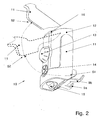
- Fig. 2 are the accessory recording 10 off Fig. 1 and shown various positions of the clamping lever 11 to explain its operation.
- the clamping lever 11 is mounted on the housing 12 and integrated in its shape so that it fits tightly against the housing 12 and so no significant protruding edges can cause unintentional operation. Shown are the positions of the clamping lever 11 during an operation thereof. In a first position S1, the clamping lever 11 is located directly on the housing 12, in this position, the clamping band 6 is made Fig. 1 determined and fixed the accessory receptacle 10 on the helmet 5.
- the clamping lever 11 is locked in the first position S1 on the housing 12, so that an accidental operation is further complicated.
- the clamping lever 11 If the clamping lever 11 is actuated - here by a rotary or pivoting movement - can in an intermediate position SZ the clamping band 6 from Fig. 1 be inserted into the accessory receptacle 10 and is secured against pulling out there.
- the clamping lever 11 is shown in dashed lines in the intermediate position SZ as a piece.
- a second position S2 of the clamping lever 11 - shown dotted in the second position S2 as a piece - the clamping band 6 is made Fig. 1 released and can be removed for disassembly of the accessory holder 10 several centimeters - or possibly completely - out of this.
- Fig. 2 also shows the electrical connection 14, for example, to supply the night-vision device 2 with information from other sources such as from radio transmission, data storage or measuring devices, the image brightness controller 13, which is provided for example for controlling the power of the residual light amplifier or for a display in the night-vision device 2, and the switch button 16, which is used to turn on and off the residual light amplifier or other signals, such as video signals, can be trained. Shown are also the battery lid closure 15 of the battery compartment and the headband 9a, 9b of the fastening component.
- the fastening component 9 is designed as a support plate 9c with retaining clips 9a, 9b. Furthermore, it has slot elements 26 as positioning elements.
- the connection with the accessory receptacle takes place via a connecting element 25, which here forms a housing rear wall of the housing 12, wherein the connecting element 25 is connected as a housing rear wall with further housing parts via a screw 28.
- the connecting element 25 has a plurality of hook elements 27 as positioning elements. By hooking in and clicking in or snapping into different hook positions, coarse adjustment is possible for different sizes of headgear. Shown in Fig.
- FIG. 3a a relative position of fastening component 9 and head cover fastener 25 for small head sizes
- Fig. 3b a relative position for headgear for "medium” head sizes
- Fig. 3c a relative position for headgear for large head sizes.
- three hook and slot elements 27,26 are provided in each case. It goes without saying that the number and design of the positioning elements can be selected as appropriate as an alternative.
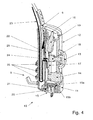
- Fig. 4 shows a section through the attachment receptacle 10, so that in particular the installation position of the clamping band 6, which is height-displaceable between the connecting element 25 as a housing rear wall and the other housing parts of the housing 12, is clearly visible.
- the clamping band 6 in a lower position - that is as far as possible in the Attachment holder 10 inserted - shown.
- the switch button 16 a push button 19
- a potentiometer 18 the image brightness controller 13
- the - made of rubbery material - switching button 16 acts on the push button 19 and the image brightness controller 13 - with the potentiometer 18 is connected.
- Pushbutton 19, potentiometer 18 and electrical connection 14 are electrically connected to the electronic unit 17, such as a printed circuit board. Other mechanical components, such as the arrangement or attachment for the controls are not described.
- a cable 23 is connected, by means of which the electronic unit 17 electrically and electronically to the night-vision device 2 from Fig. 1 is attachable.
- the cable 23 is guided in the accessory receptacle 10 through a grommet 24 through an electronics cover 22, which is used for waterproof separation between the strap 6 and the electrical and electronic accessories in the accessory receptacle 10.
- the cable 23 is further guided in the attachment receptacle 10 in a loop around the tension band 6, so that a withdrawal of the tension band 6 is easily possible without the cable 23 to injure or buckling.
- the cable 23 runs along the tensioning band 6 and is thus completely covered and protected in the area of the headgear against the risk of injury from the tensioning band 6.
- Batteries 34 (see Fig. 5 ) as an energy source can be inserted into a battery compartment of the auxiliary device receptacle 10 or removed therefrom.
- To open and close the battery compartment is a battery cover 20 via a seal 21 on the housing 12.
- With a rotatable battery lid closure 15 which is rotatably connected to a lock 15b by means of screw 15a, the battery compartment cover 20 is held via an undercut in the housing 12 depending on the rotational position of the battery lid closure 15 or released for opening.
- the tension band 6 is composed of a first tension band part 6a and a second tension band part 6b.
- the first strap portion 6a is in the position of use on the headgear, such as the helmet 5 (see. Fig. 1 ) and is made for example of textile fabric or a hose-like rubber-like material.
- the second tension band part 6b is here made of plastic and centrally has a cable channel 38 for the cable 23 Fig. 4 on, which largely encloses the cable 23.
- the cable 23 may advantageously be guided to the sighting device in the tensioning band 6 (in a cable channel both in the first and in the second tensioning band part 6a, 6b), for example in a shell through an opening through the tensioning band 6 or a tension band 6 - for example Plastic - illustrated cable duct.
- the guide can also take place within the second tension band part 6b and below the first tension band part 6a.
- the second clamping band part 6b has right and left of the cable channel 38 along a clamping portion 6b 'locking elements each in the form of a toothing 30a, 30b.
- the clamping region 6b 'defines the region of the tension band 6 - or here the second tension band part 6b - which is fully slidable into the accessory receptacle 10.
- connection of the two clamping band parts via a flange-like ausgestaltetes connecting part 36, which may be provided on the first or second clamping band part 6a, 6b.
- the connection of the two materials of the two clamping band parts can be done by rivets or screws. Of course, just as an alternative conventional connection can be selected.
- Fig. 5 is also the guidance of the tension band 6 in the accessory receptacle 10 hinted at. This has along the connecting element 25 on the right and left guides 37, by means of which the clamping band 6 is guided laterally exactly. Also shown are attachments of the accessory receptacle 10, as they are arranged in the use position.
- the mounted on the electronics unit 17 components push-button 19, Potentiometer 18, and electrical connection 14 are arranged centrally.
- batteries 34 Arranged on the outer sides are batteries 34, which are connected via resilient battery contacts 35 to the electronic unit 17. The interconnection of the other two battery contacts is housed in the battery lid in a conventional manner and not shown here.
- the electronics cover 22 is disposed between the strap 6 and the electrical and electronic accessories.
- connection component 25 with guides 37 and guided in the guides 37 tension band 6.
- the clamping band 6 is slidable along the clamping portion 6b 'in the guides 37 from an initial position to an end position.
- the starting position may be the position in which the clamping region 6b 'is located minimally in the auxiliary device receptacle 10, that is to say it has been pulled out to the maximum extent. The complete withdrawal from the accessory receptacle 10 may be possible.
- the complete withdrawal but also - for example by means of a stop element - are prevented, so that a complete separation from the strap 6 is avoided, so that the attachment receptacle 10 never only on the cable 23 (see. Fig. 4 ) hangs.
- end position is to be understood as meaning the position in which the entire clamping region 6b 'is pushed into the auxiliary device receptacle 10.
- the clamping device comprises the actuating element designed as a tensioning lever 11.
- the clamping lever 11 is designed as a latch 29 locking element of the clamping device can be brought into a plurality of positions.
- the pawl 29 has guide surfaces 45a, 45b and pawl blades 44a, 44b, wherein the pawls 44a, 44b designed as corresponding to the teeth 30a, 30b latching elements in the clamping portion 6b 'of the second clamping band portion 6b by engaging latching elements to the teeth 30a , 30b.
- the action of the gears 30a, 30b and the pawls 44a, 44b can be as well along with a toothing of the clamping region 6b 'and a pawl blade - the embodiment of the embodiment shown with two toothings 30a, 30b and pawl blades 44a, 44b results from the design of the cable duct.
- embodiments with right or left along the clamping portion 6b 'guided toothing and corresponding latching and optionally corresponding left or right guided cable channel would be.
- the tensioning lever 11 is connected via pivot members 40 in bearings 41 - e.g. correspondingly executed recesses - rotatably mounted by the connecting element 25 formed housing rear wall.
- the pivot bearing elements 40 are on the one hand firmly connected to the clamping lever 11 and on the other hand by means of pins 42 eccentrically connected to the axis of rotation of the clamping lever 11 with connecting rods 39 rotatably.
- the pawl 29 or the pawl blades 44a, 44b is or are rotatably supported via armpit elements 43 in the connecting rod 39.
- the displacement of the pawl 29 is also still controlled by the guide surfaces 45a, 45b.
- the control takes place in cooperation with the guides 37 of the connecting element 25, in particular with slide-like guide elements 31 of the guides 37.
- With continuous rotation of the clamping lever 11 about the axis of rotation is moved due to the eccentric arrangement of the pins 42 to the axis of rotation, the pawl 29 via the connecting rod 39.
- the guide surfaces 45 of the pawl 29 are pushed onto the backdrop-like guide elements 31, whereby the - pawls 44a, 44b lifted and a complete release of the tension band 6 is achieved.
- the operation is explained in more detail in the following figures.
- the pawl 29 is moved downward, the pawl blades 44a, 44b engage in the sawtooth-like teeth 30a, 30b and push the latch lever 11 as the pawl 11 advances Tightening strap 6 down, which causes a lashing of the tension band 6.
- a leaf spring 46 is mounted in the auxiliary device receptacle 10 - for example on a housing part, not shown.
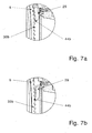
- FIGS. 7a and 7b is shown in a detailed view of the tension band 6 in the attachment receptacle and the interaction of a pawl knife 44b of the pawl 29 with a toothing 30b of the tension band 6.
- Fig. 7a is the pawl knife 44b on the tooth back of the toothing 30b - which ratchet position of the intermediate position SZ of the clamping lever 11 from Fig. 2 equivalent.
- the clamping band 6 can be moved without resistance down, with each tooth, the pawl 29 secures the strap 6 against withdrawal.
- the pawl knife 44b dips accordingly Fig.
- the clamping band 6 can at the first position S1 or the intermediate position SZ of the clamping lever 11 (according Fig. 2 ) are pushed manually into the accessory holder.
- the movement of the lever from the first position S1 to the second position S2 causes the engagement in the toothings 30a, 30b (FIG. Fig. 6 ) and shifting the pawls 44a, 44b ( Fig. 6 ) down so that the tensioned over the headgear strap tightened and the accessory receptacle 10 is pressed firmly to the headgear (see. Fig. 1 ).
- FIGS. 8a to 8c show in section detail views of the positions of the pawl 29 when moving the same in the guides 37 of the accessory recording.
- the guides comprise a backdrop-like guide element 31. Shown is the pawl 29 with the pawl 44 b and its guide surface 45 b.
- the guide surface 45b has a cam 32b which, depending on the position of the clamping lever 11 (see FIG. Fig. 2 ) determines the stop position of the pawl 29 (correspondingly, the guide surface 45a from Fig. 6 a cam 32a).
- FIGS. 8a and 8b show the position of the pawl 29 at the position of the clamping lever in the first position S1 and the intermediate position SZ as shown in FIG Fig. 2 .
- the guide surface 45b is displaced in the guide 37 along a region B to the backdrop-like guide member 31.
- the pawl knife 44b of the pawl 29 can dive into the toothing of the tension band, so that the pawl 29 secures the tension band in every position against pulling out.
- Fig. 8c shows the pawl 29 in the second position S2 of the clamping lever as shown in FIG Fig. 2 ,
- the guide surface 45b is slid onto the slide-like guide element 31.
- the pawl 29 is thereby forcibly rotated by the cam 32 - in the representation counterclockwise - so that the pawl knife 44 b can not dive into the teeth of the tension band.
- the holding of the tension band is prevented by the pawl 44 b, whereby the tension band can be pulled out, so that the accessory receptacle is removable from the headgear.
Landscapes
- Helmets And Other Head Coverings (AREA)
- Adornments (AREA)
- Toys (AREA)
Claims (9)
- Dispositif de montage pour des accessoires (10) pour la liaison électrique et/ou électronique, en particulier au moyen d'un câble (23), à un dispositif de vision, en particulier un dispositif de vision nocturne (2), susceptible d'être fixé sur un premier côté d'un couvre-chef, tel qu'un casque (5), les accessoires constituant des composants électriques et/ou électroniques et mécaniques, intégrés ou susceptibles d'être intégrés,
le dispositif de montage pour des accessoires (10) étant susceptible d'être fixé, à l'aide d'au moins un composant de fixation (9), sur un deuxième côté, sensiblement opposé au premier côté, du couvre-chef,
caractérisé en ce que
le dispositif de montage pour des accessoires (10) présente un dispositif tendeur, pour établir une liaison de maintien, indirecte ou directe - par l'intermédiaire d'un élément tendeur, tel qu'un ruban tendeur (6) - par rapport à un premier côté et/ou par rapport au dispositif de vision. - Dispositif de montage selon la revendication 1, caractérisé en ce que le dispositif tendeur présente au moins un élément de blocage, tel qu'un cliquet (29), pour l'élément tendeur, l'élément de blocage étant susceptible d'être placé au moins dans- une première position, pour bloquer l'élément tendeur, et- une deuxième position, pour libérer l'élément tendeur, l'élément tendeur étant déplaçable, en particulier à l'intérieur du dispositif de montage pour des accessoires (10).
- Dispositif de montage selon la revendication 2, caractérisé en ce que le dispositif tendeur présente un élément de réglage, tel qu'un levier de serrage (11), pour l'élément de blocage.
- Dispositif de montage selon la revendication 3, caractérisé en ce que le dispositif de montage pour des accessoires (10) présente des paliers (41), pour le montage à rotation autour d'un axe de rotation de l'élément de réglage, par l'intermédiaire d'éléments de palier de rotation (40).
- Dispositif de montage selon la revendication 4, caractérisé en ce que les éléments de palier de rotation (40) sont fixés de manière excentrique par rapport à l'axe de rotation, par exemple par l'intermédiaire de tourillons (42), sur des éléments de démultiplication d'effort, tels que des bielles (39), auxquelles en outre le au moins un élément de blocage est monté à rotation sur des éléments formant axe (43), de manière qu'un mouvement de rotation de l'élément de réglage autour de l'axe de rotation provoque une translation de l'élément de blocage.
- Dispositif de montage selon l'une des revendications précédentes, caractérisé en ce que l'élément tendeur présente un canal à câble (38) pour le câble (23).
- Dispositif de montage selon l'une des revendications 5 ou 6, caractérisé en ce que le dispositif de montage pour des accessoires (10) présente des guidages (37) pour l'élément tendeur, les guidages (37) comprenant des éléments de guidage (31) du genre de coulisses, pour coopérer avec des faces de guidage (45), par l'intermédiaire desquelles la translation de l'élément de blocage est commandée.
- Dispositif de montage selon l'une des revendications précédentes, caractérisé en ce que- dans une zone de mise sous tension mécanique (6b'), associée au dispositif de montage pour des accessoires (10), l'élément tendeur présente, présente des éléments d'encliquetage, se présentant par exemple sous la forme de dentures (30a, 30b),
et- l'élément de blocage présente au moins un élément d'indexation, tel qu'une lame de cliquet (44a, 44b), devant coopérer avec les éléments d'encliquetage, faisant que le dispositif de montage pour des accessoires (10) et l'élément tendeur sont susceptibles d'être positionnés différemment l'un par rapport à l'autre, le long de la zone de mise sous tension mécanique (6b'). - Dispositif de montage selon l'une des revendications précédentes, avec au moins un élément de liaison (25) pour le composant de fixation, l'élément de liaison (25) et le composant de fixation (6) étant susceptibles d'être positionnés différemment l'un par rapport à l'autre par l'intermédiaire d'éléments de positionnement (26, 27), de manière que l'agencement du dispositif de montage pour des accessoires (10) - par rapport à la position d'utilisation du couvre-chef - soit réglable en hauteur.
Priority Applications (3)
| Application Number | Priority Date | Filing Date | Title |
|---|---|---|---|
| DE502006005098T DE502006005098D1 (de) | 2006-03-10 | 2006-03-10 | Auf einer kopfbedeckung befestigbare aufnahme für zusatzgeräte für sichtgeräte |
| AT06110937T ATE445343T1 (de) | 2006-03-10 | 2006-03-10 | Auf einer kopfbedeckung befestigbare aufnahme für zusatzgeräte für sichtgeräte |
| EP06110937A EP1832189B1 (fr) | 2006-03-10 | 2006-03-10 | Dispositif pour monter un accessoire d'un dispositif de vision sur un couvre-chef |
Applications Claiming Priority (1)
| Application Number | Priority Date | Filing Date | Title |
|---|---|---|---|
| EP06110937A EP1832189B1 (fr) | 2006-03-10 | 2006-03-10 | Dispositif pour monter un accessoire d'un dispositif de vision sur un couvre-chef |
Publications (2)
| Publication Number | Publication Date |
|---|---|
| EP1832189A1 EP1832189A1 (fr) | 2007-09-12 |
| EP1832189B1 true EP1832189B1 (fr) | 2009-10-14 |
Family
ID=36754280
Family Applications (1)
| Application Number | Title | Priority Date | Filing Date |
|---|---|---|---|
| EP06110937A Expired - Lifetime EP1832189B1 (fr) | 2006-03-10 | 2006-03-10 | Dispositif pour monter un accessoire d'un dispositif de vision sur un couvre-chef |
Country Status (3)
| Country | Link |
|---|---|
| EP (1) | EP1832189B1 (fr) |
| AT (1) | ATE445343T1 (fr) |
| DE (1) | DE502006005098D1 (fr) |
Cited By (1)
| Publication number | Priority date | Publication date | Assignee | Title |
|---|---|---|---|---|
| WO2024141303A1 (fr) * | 2022-12-28 | 2024-07-04 | Pfanner Schutzbekleidung Gmbh | Support de batterie, lumière de casque dotée d'un support de batterie et casque de protection doté d'une lumière de casque |
Families Citing this family (4)
| Publication number | Priority date | Publication date | Assignee | Title |
|---|---|---|---|---|
| AT521239B1 (de) | 2018-05-08 | 2020-02-15 | Leader Photonics Gmbh | Halterung zum Tragen eines Sensorsystems eines Feuerwehrhelms |
| US11614612B2 (en) * | 2020-01-18 | 2023-03-28 | TNVC, Inc. | Modular binocular night vision device |
| US11419382B2 (en) | 2020-04-14 | 2022-08-23 | Wilcox Industries Corp. | Modular helmet system |
| CN111273450B (zh) * | 2020-04-14 | 2020-12-08 | 湖南翰坤实业有限公司 | 一种vr体验头盔及其平衡调节方法 |
Family Cites Families (5)
| Publication number | Priority date | Publication date | Assignee | Title |
|---|---|---|---|---|
| US5226181A (en) * | 1992-01-17 | 1993-07-13 | Gentex Corporation | Mounting device for night vision mount and goggle assembly |
| US5467479A (en) * | 1993-05-07 | 1995-11-21 | Varo Inc. | Night vision goggle mount |
| US5506730A (en) * | 1993-09-09 | 1996-04-09 | Litton Systems, Inc. | Flip-up helmet mount for night vision goggle |
| US5683831A (en) * | 1996-03-29 | 1997-11-04 | Itt Defense, Inc. | Compact battery pack for a helmet mounted night vision device |
| WO2006065805A2 (fr) * | 2004-12-17 | 2006-06-22 | Insight Technology, Inc. | Procede et appareil pour monter un systeme de vision |
-
2006
- 2006-03-10 AT AT06110937T patent/ATE445343T1/de active
- 2006-03-10 EP EP06110937A patent/EP1832189B1/fr not_active Expired - Lifetime
- 2006-03-10 DE DE502006005098T patent/DE502006005098D1/de not_active Expired - Lifetime
Cited By (1)
| Publication number | Priority date | Publication date | Assignee | Title |
|---|---|---|---|---|
| WO2024141303A1 (fr) * | 2022-12-28 | 2024-07-04 | Pfanner Schutzbekleidung Gmbh | Support de batterie, lumière de casque dotée d'un support de batterie et casque de protection doté d'une lumière de casque |
Also Published As
| Publication number | Publication date |
|---|---|
| ATE445343T1 (de) | 2009-10-15 |
| EP1832189A1 (fr) | 2007-09-12 |
| DE502006005098D1 (de) | 2009-11-26 |
Similar Documents
| Publication | Publication Date | Title |
|---|---|---|
| US10004289B2 (en) | Helmet mounting systems | |
| DE69204248T2 (de) | Schirme und Blendschutzfilter zur Montage auf Monitoren. | |
| US7963426B2 (en) | Receptacle which can be fixed to a head covering and is intended for attachments for sighting devices | |
| EP2498636B1 (fr) | Casque de protection destiné notamment à des ouvriers forestiers | |
| DE29713427U1 (de) | Kamerahalter zur Befestigung an einem Schwenkkopf | |
| DE602004010072T2 (de) | Mehrzwecktragsystem für motorradzubehör | |
| WO2019170380A1 (fr) | Siège de véhicule | |
| DE102016221434A1 (de) | Monitor eines Kamera-Monitor-Systems | |
| EP1832189A1 (fr) | Dispositif pour monter un accessoire d'un dispositif de vision sur un couvre-chef | |
| DE29722983U1 (de) | Gürtelschnalle | |
| DE202005013695U1 (de) | Verstellvorrichtung bei einem Helm | |
| WO2013007409A1 (fr) | Support de caméra pour un skieur | |
| DE202018105754U1 (de) | Rückspiegelbaugruppe, die eine integrierte Halterung für eine elektronische Vorrichtung einbindet | |
| DE102013019775B4 (de) | Schutzhelmsystem | |
| EP1656045B1 (fr) | Casque | |
| DE102004040049A1 (de) | Nachgeh-Arbeitsmaschine | |
| DE202018106560U1 (de) | Blendenbaugruppe mit einer Aufnahme für eine elektronische Vorrichtung | |
| DE69404761T2 (de) | Vorrichtung zur gelenkigen Befestigung einer Visierscheibe an einem Helm | |
| DE19520386C2 (de) | Haltevorrichtung für ein Zubehörteil an einem Helm und mit der Vorrichtung ausgestatteter Helm | |
| DE102007046693B4 (de) | Anzeigevorrichtung | |
| DE202025004165U1 (de) | Halteeinrichtung und Aufbewahrungssystem | |
| DE2925414A1 (de) | Stativ fuer filmkameras u.dgl. | |
| DE102005063198B4 (de) | Kopf- und Helmkamera | |
| DE602005005819T2 (de) | Montageanordnung für zusätzlichen Rückblickspiegel | |
| DE69711143T2 (de) | Vorrichtung zur Anpassung und Befestigung eines Helmes an den Kopf eines Benutzers |
Legal Events
| Date | Code | Title | Description |
|---|---|---|---|
| PUAI | Public reference made under article 153(3) epc to a published international application that has entered the european phase |
Free format text: ORIGINAL CODE: 0009012 |
|
| AK | Designated contracting states |
Kind code of ref document: A1 Designated state(s): AT BE BG CH CY CZ DE DK EE ES FI FR GB GR HU IE IS IT LI LT LU LV MC NL PL PT RO SE SI SK TR |
|
| AX | Request for extension of the european patent |
Extension state: AL BA HR MK YU |
|
| 17P | Request for examination filed |
Effective date: 20080308 |
|
| AKX | Designation fees paid |
Designated state(s): AT BE BG CH CY CZ DE DK EE ES FI FR GB GR HU IE IS IT LI LT LU LV MC NL PL PT RO SE SI SK TR |
|
| 17Q | First examination report despatched |
Effective date: 20080502 |
|
| GRAP | Despatch of communication of intention to grant a patent |
Free format text: ORIGINAL CODE: EPIDOSNIGR1 |
|
| GRAS | Grant fee paid |
Free format text: ORIGINAL CODE: EPIDOSNIGR3 |
|
| GRAA | (expected) grant |
Free format text: ORIGINAL CODE: 0009210 |
|
| AK | Designated contracting states |
Kind code of ref document: B1 Designated state(s): AT BE BG CH CY CZ DE DK EE ES FI FR GB GR HU IE IS IT LI LT LU LV MC NL PL PT RO SE SI SK TR |
|
| REG | Reference to a national code |
Ref country code: GB Ref legal event code: FG4D Free format text: NOT ENGLISH |
|
| REG | Reference to a national code |
Ref country code: CH Ref legal event code: EP |
|
| REG | Reference to a national code |
Ref country code: IE Ref legal event code: FG4D |
|
| REF | Corresponds to: |
Ref document number: 502006005098 Country of ref document: DE Date of ref document: 20091126 Kind code of ref document: P |
|
| LTIE | Lt: invalidation of european patent or patent extension |
Effective date: 20091014 |
|
| NLV1 | Nl: lapsed or annulled due to failure to fulfill the requirements of art. 29p and 29m of the patents act | ||
| PG25 | Lapsed in a contracting state [announced via postgrant information from national office to epo] |
Ref country code: SE Free format text: LAPSE BECAUSE OF FAILURE TO SUBMIT A TRANSLATION OF THE DESCRIPTION OR TO PAY THE FEE WITHIN THE PRESCRIBED TIME-LIMIT Effective date: 20091014 Ref country code: IS Free format text: LAPSE BECAUSE OF FAILURE TO SUBMIT A TRANSLATION OF THE DESCRIPTION OR TO PAY THE FEE WITHIN THE PRESCRIBED TIME-LIMIT Effective date: 20100214 Ref country code: PT Free format text: LAPSE BECAUSE OF FAILURE TO SUBMIT A TRANSLATION OF THE DESCRIPTION OR TO PAY THE FEE WITHIN THE PRESCRIBED TIME-LIMIT Effective date: 20100215 Ref country code: ES Free format text: LAPSE BECAUSE OF FAILURE TO SUBMIT A TRANSLATION OF THE DESCRIPTION OR TO PAY THE FEE WITHIN THE PRESCRIBED TIME-LIMIT Effective date: 20100125 Ref country code: FI Free format text: LAPSE BECAUSE OF FAILURE TO SUBMIT A TRANSLATION OF THE DESCRIPTION OR TO PAY THE FEE WITHIN THE PRESCRIBED TIME-LIMIT Effective date: 20091014 Ref country code: LT Free format text: LAPSE BECAUSE OF FAILURE TO SUBMIT A TRANSLATION OF THE DESCRIPTION OR TO PAY THE FEE WITHIN THE PRESCRIBED TIME-LIMIT Effective date: 20091014 |
|
| REG | Reference to a national code |
Ref country code: IE Ref legal event code: FD4D |
|
| PG25 | Lapsed in a contracting state [announced via postgrant information from national office to epo] |
Ref country code: PL Free format text: LAPSE BECAUSE OF FAILURE TO SUBMIT A TRANSLATION OF THE DESCRIPTION OR TO PAY THE FEE WITHIN THE PRESCRIBED TIME-LIMIT Effective date: 20091014 Ref country code: LV Free format text: LAPSE BECAUSE OF FAILURE TO SUBMIT A TRANSLATION OF THE DESCRIPTION OR TO PAY THE FEE WITHIN THE PRESCRIBED TIME-LIMIT Effective date: 20091014 Ref country code: SI Free format text: LAPSE BECAUSE OF FAILURE TO SUBMIT A TRANSLATION OF THE DESCRIPTION OR TO PAY THE FEE WITHIN THE PRESCRIBED TIME-LIMIT Effective date: 20091014 |
|
| PG25 | Lapsed in a contracting state [announced via postgrant information from national office to epo] |
Ref country code: RO Free format text: LAPSE BECAUSE OF FAILURE TO SUBMIT A TRANSLATION OF THE DESCRIPTION OR TO PAY THE FEE WITHIN THE PRESCRIBED TIME-LIMIT Effective date: 20091014 Ref country code: BG Free format text: LAPSE BECAUSE OF FAILURE TO SUBMIT A TRANSLATION OF THE DESCRIPTION OR TO PAY THE FEE WITHIN THE PRESCRIBED TIME-LIMIT Effective date: 20100114 Ref country code: EE Free format text: LAPSE BECAUSE OF FAILURE TO SUBMIT A TRANSLATION OF THE DESCRIPTION OR TO PAY THE FEE WITHIN THE PRESCRIBED TIME-LIMIT Effective date: 20091014 Ref country code: IE Free format text: LAPSE BECAUSE OF FAILURE TO SUBMIT A TRANSLATION OF THE DESCRIPTION OR TO PAY THE FEE WITHIN THE PRESCRIBED TIME-LIMIT Effective date: 20091014 Ref country code: DK Free format text: LAPSE BECAUSE OF FAILURE TO SUBMIT A TRANSLATION OF THE DESCRIPTION OR TO PAY THE FEE WITHIN THE PRESCRIBED TIME-LIMIT Effective date: 20091014 |
|
| PLBE | No opposition filed within time limit |
Free format text: ORIGINAL CODE: 0009261 |
|
| STAA | Information on the status of an ep patent application or granted ep patent |
Free format text: STATUS: NO OPPOSITION FILED WITHIN TIME LIMIT |
|
| PG25 | Lapsed in a contracting state [announced via postgrant information from national office to epo] |
Ref country code: CZ Free format text: LAPSE BECAUSE OF FAILURE TO SUBMIT A TRANSLATION OF THE DESCRIPTION OR TO PAY THE FEE WITHIN THE PRESCRIBED TIME-LIMIT Effective date: 20091014 Ref country code: SK Free format text: LAPSE BECAUSE OF FAILURE TO SUBMIT A TRANSLATION OF THE DESCRIPTION OR TO PAY THE FEE WITHIN THE PRESCRIBED TIME-LIMIT Effective date: 20091014 |
|
| 26N | No opposition filed |
Effective date: 20100715 |
|
| BERE | Be: lapsed |
Owner name: VECTRONIX A.G. Effective date: 20100331 |
|
| PG25 | Lapsed in a contracting state [announced via postgrant information from national office to epo] |
Ref country code: GR Free format text: LAPSE BECAUSE OF FAILURE TO SUBMIT A TRANSLATION OF THE DESCRIPTION OR TO PAY THE FEE WITHIN THE PRESCRIBED TIME-LIMIT Effective date: 20100115 Ref country code: MC Free format text: LAPSE BECAUSE OF NON-PAYMENT OF DUE FEES Effective date: 20100331 |
|
| PG25 | Lapsed in a contracting state [announced via postgrant information from national office to epo] |
Ref country code: BE Free format text: LAPSE BECAUSE OF NON-PAYMENT OF DUE FEES Effective date: 20100331 |
|
| PG25 | Lapsed in a contracting state [announced via postgrant information from national office to epo] |
Ref country code: IT Free format text: LAPSE BECAUSE OF FAILURE TO SUBMIT A TRANSLATION OF THE DESCRIPTION OR TO PAY THE FEE WITHIN THE PRESCRIBED TIME-LIMIT Effective date: 20091014 |
|
| PG25 | Lapsed in a contracting state [announced via postgrant information from national office to epo] |
Ref country code: CY Free format text: LAPSE BECAUSE OF FAILURE TO SUBMIT A TRANSLATION OF THE DESCRIPTION OR TO PAY THE FEE WITHIN THE PRESCRIBED TIME-LIMIT Effective date: 20091014 |
|
| PG25 | Lapsed in a contracting state [announced via postgrant information from national office to epo] |
Ref country code: HU Free format text: LAPSE BECAUSE OF FAILURE TO SUBMIT A TRANSLATION OF THE DESCRIPTION OR TO PAY THE FEE WITHIN THE PRESCRIBED TIME-LIMIT Effective date: 20100415 Ref country code: NL Free format text: LAPSE BECAUSE OF FAILURE TO SUBMIT A TRANSLATION OF THE DESCRIPTION OR TO PAY THE FEE WITHIN THE PRESCRIBED TIME-LIMIT Effective date: 20091014 Ref country code: LU Free format text: LAPSE BECAUSE OF NON-PAYMENT OF DUE FEES Effective date: 20100310 |
|
| PG25 | Lapsed in a contracting state [announced via postgrant information from national office to epo] |
Ref country code: TR Free format text: LAPSE BECAUSE OF FAILURE TO SUBMIT A TRANSLATION OF THE DESCRIPTION OR TO PAY THE FEE WITHIN THE PRESCRIBED TIME-LIMIT Effective date: 20091014 |
|
| REG | Reference to a national code |
Ref country code: AT Ref legal event code: MM01 Ref document number: 445343 Country of ref document: AT Kind code of ref document: T Effective date: 20110310 |
|
| PG25 | Lapsed in a contracting state [announced via postgrant information from national office to epo] |
Ref country code: AT Free format text: LAPSE BECAUSE OF NON-PAYMENT OF DUE FEES Effective date: 20110310 |
|
| REG | Reference to a national code |
Ref country code: FR Ref legal event code: PLFP Year of fee payment: 10 |
|
| PGFP | Annual fee paid to national office [announced via postgrant information from national office to epo] |
Ref country code: DE Payment date: 20150320 Year of fee payment: 10 |
|
| PGFP | Annual fee paid to national office [announced via postgrant information from national office to epo] |
Ref country code: FR Payment date: 20150319 Year of fee payment: 10 Ref country code: GB Payment date: 20150319 Year of fee payment: 10 |
|
| REG | Reference to a national code |
Ref country code: DE Ref legal event code: R119 Ref document number: 502006005098 Country of ref document: DE |
|
| GBPC | Gb: european patent ceased through non-payment of renewal fee |
Effective date: 20160310 |
|
| REG | Reference to a national code |
Ref country code: FR Ref legal event code: ST Effective date: 20161130 |
|
| PG25 | Lapsed in a contracting state [announced via postgrant information from national office to epo] |
Ref country code: GB Free format text: LAPSE BECAUSE OF NON-PAYMENT OF DUE FEES Effective date: 20160310 Ref country code: DE Free format text: LAPSE BECAUSE OF NON-PAYMENT OF DUE FEES Effective date: 20161001 Ref country code: FR Free format text: LAPSE BECAUSE OF NON-PAYMENT OF DUE FEES Effective date: 20160331 |
|
| PGFP | Annual fee paid to national office [announced via postgrant information from national office to epo] |
Ref country code: CH Payment date: 20170303 Year of fee payment: 12 |
|
| REG | Reference to a national code |
Ref country code: CH Ref legal event code: PL |
|
| PG25 | Lapsed in a contracting state [announced via postgrant information from national office to epo] |
Ref country code: CH Free format text: LAPSE BECAUSE OF NON-PAYMENT OF DUE FEES Effective date: 20180331 Ref country code: LI Free format text: LAPSE BECAUSE OF NON-PAYMENT OF DUE FEES Effective date: 20180331 |