EP1832229A1 - Procede d' imagerie a resonance magnetique et appareil d' imagerie a resonance magnetique - Google Patents
Procede d' imagerie a resonance magnetique et appareil d' imagerie a resonance magnetique Download PDFInfo
- Publication number
- EP1832229A1 EP1832229A1 EP04822523A EP04822523A EP1832229A1 EP 1832229 A1 EP1832229 A1 EP 1832229A1 EP 04822523 A EP04822523 A EP 04822523A EP 04822523 A EP04822523 A EP 04822523A EP 1832229 A1 EP1832229 A1 EP 1832229A1
- Authority
- EP
- European Patent Office
- Prior art keywords
- magnetic field
- radio frequency
- magnetic resonance
- resonance imaging
- sample
- Prior art date
- Legal status (The legal status is an assumption and is not a legal conclusion. Google has not performed a legal analysis and makes no representation as to the accuracy of the status listed.)
- Withdrawn
Links
- 238000002595 magnetic resonance imaging Methods 0.000 title claims abstract description 30
- 238000000034 method Methods 0.000 title claims abstract description 11
- 230000001052 transient effect Effects 0.000 claims abstract description 41
- 230000003068 static effect Effects 0.000 claims abstract description 35
- 238000003384 imaging method Methods 0.000 description 12
- 238000010586 diagram Methods 0.000 description 6
- 230000005415 magnetization Effects 0.000 description 6
- 238000001208 nuclear magnetic resonance pulse sequence Methods 0.000 description 4
- 238000005259 measurement Methods 0.000 description 3
- 239000003990 capacitor Substances 0.000 description 2
- 238000012545 processing Methods 0.000 description 2
- 230000009466 transformation Effects 0.000 description 2
- 238000004804 winding Methods 0.000 description 2
- 230000001133 acceleration Effects 0.000 description 1
- 238000001514 detection method Methods 0.000 description 1
- 238000011161 development Methods 0.000 description 1
- 238000003745 diagnosis Methods 0.000 description 1
- 239000003814 drug Substances 0.000 description 1
- 230000005284 excitation Effects 0.000 description 1
- 230000004907 flux Effects 0.000 description 1
- 210000004072 lung Anatomy 0.000 description 1
- 239000000463 material Substances 0.000 description 1
- 230000003387 muscular Effects 0.000 description 1
- 210000000653 nervous system Anatomy 0.000 description 1
- 235000001968 nicotinic acid Nutrition 0.000 description 1
- 230000005311 nuclear magnetism Effects 0.000 description 1
- 230000000704 physical effect Effects 0.000 description 1
- 238000011160 research Methods 0.000 description 1
- 229920006395 saturated elastomer Polymers 0.000 description 1
- 239000000126 substance Substances 0.000 description 1
- 238000012800 visualization Methods 0.000 description 1
Images


Classifications
-
- G—PHYSICS
- G01—MEASURING; TESTING
- G01R—MEASURING ELECTRIC VARIABLES; MEASURING MAGNETIC VARIABLES
- G01R33/00—Arrangements or instruments for measuring magnetic variables
- G01R33/20—Arrangements or instruments for measuring magnetic variables involving magnetic resonance
- G01R33/28—Details of apparatus provided for in groups G01R33/44 - G01R33/64
- G01R33/32—Excitation or detection systems, e.g. using radio frequency signals
- G01R33/34—Constructional details, e.g. resonators, specially adapted to MR
- G01R33/34046—Volume type coils, e.g. bird-cage coils; Quadrature bird-cage coils; Circularly polarised coils
-
- G—PHYSICS
- G01—MEASURING; TESTING
- G01R—MEASURING ELECTRIC VARIABLES; MEASURING MAGNETIC VARIABLES
- G01R33/00—Arrangements or instruments for measuring magnetic variables
- G01R33/20—Arrangements or instruments for measuring magnetic variables involving magnetic resonance
- G01R33/44—Arrangements or instruments for measuring magnetic variables involving magnetic resonance using nuclear magnetic resonance [NMR]
- G01R33/48—NMR imaging systems
- G01R33/483—NMR imaging systems with selection of signals or spectra from particular regions of the volume, e.g. in vivo spectroscopy
- G01R33/4831—NMR imaging systems with selection of signals or spectra from particular regions of the volume, e.g. in vivo spectroscopy using B1 gradients, e.g. rotating frame techniques, use of surface coils
Definitions
- the present invention relates to a magnetic resonance imaging method and a magnetic resonance imaging apparatus which visualize invisible information inside a living body or a material using a magnetic resonance phenomenon.
- a magnetic resonance signal has a frequency, a phase, and signal strength as information. Although information regarding a position can be encoded in any of these, a best policy does not encode positional information in signal strength.
- the purpose of the magnetic resonance imaging is, however, to produce spatial distribution of signal strength. Then, generally, positional information is encoded in the frequency and the phase.
- a conventional magnetic resonance imaging uses a static magnetic field gradient so as to obtain positional information.
- a magnetic resonance imaging which used a radio frequency magnetic field gradient only for phase encoding in a laboratory coordinate system is proposed, this method uses the static magnetic field gradient for signal observation (non-patent document 1).
- Non-patent document 1 D.I. Hoult, "Rotating Framemaschinematorgraphy", Journal of Magnetic Resonance 33, 183-197 (1979)
- an object of the present invention is to provide a magnetic resonance imaging method and a magnetic resonance imaging apparatus which can obtain a high-quality image at high speed without obstructions, such as an artifact by a distribution of a magnetic susceptibility and a myoneural stimulus by an eddy current using only radio frequency magnetic field (rotating magnetic field) gradients so as to obtain positional information.
- a magnetic resonance imaging method comprising sequentially applying radio frequency magnetic field gradient pulses to a sample placed in a static magnetic field, in two axial directions which do not include a direction of the static magnetic field among three axial directions being mutually orthogonal, which include the direction of the static magnetic field as one axis, and obtaining a magnetic resonance image of the sample by using a transient nutation signal generated in the sample during the application of the radio frequency magnetic field gradient pulse applied for the last time.
- a magnetic resonance image of the above-mentioned sample can be also obtained by sequentially applying radio frequency magnetic field gradient pulses in three axial directions which include the above-mentioned static magnetic field direction and which are mutually orthogonal, and using a transient nutation signal generated in the above-mentioned sample during an application of the radio frequency magnetic field gradient pulse applied at an end of that time.
- the radio frequency magnetic field gradient pulses are sequentially applied in three axial directions being mutually orthogonal, which include the direction of the static magnetic field, and a magnetic resonance image of the sample can be also obtained by using a transient nutation signal generated in the sample during the application of the radio frequency magnetic field gradient pulse applied for the last time.
- a magnetic resonance imaging apparatus comprises a phase encoding coil and a frequency encoding coil for applying radio frequency magnetic field gradient pulses to a sample placed in a static magnetic field, respectively, in two axial directions which do not include a direction of the static magnetic field among three axial directions being mutually orthogonal, which include the direction of the static magnetic field as one axis, a detector for detecting a transient nutation signal generated in the sample, the transient nutation signal being included in the radio frequency magnetic field gradient pulse obtained through the frequency encoding coil, and a storage and arithmetic unit for obtaining a magnetic resonance image of the sample by storing and arithmetically operating the signal obtained through the detector.
- it can also comprise two phase encoding coils and one frequency encoding coil for applying radio frequency magnetic field gradient pulses, respectively, in three axial directions being mutually orthogonal, which include the static magnetic field direction.
- the radio frequency magnetic field gradient pulse is applied to one of the phase encoding coils and the frequency encoding coil, it is preferable to shift a resonant frequency of the remaining coil.
- a magnetic resonance imaging method and a magnetic resonance imaging apparatus which can obtain a high-quality image at high speed without obstructions, such as an artifact by a distribution of a magnetic susceptibility and a myoneural stimulus by an eddy current by measuring a transient nutation signal using only radio frequency magnetic field gradients as magnetic field gradients for encoding positional information.
- the present invention measures a transient nutation signal using only radio frequency magnetic field gradients as magnetic field gradients for encoding positional information. Thereby, it is possible to obtain a high-quality image at high speed without obstructions such as an artifact by a distribution of a magnetic susceptibility and a myoneural stimulus by an eddy current.
- a transient nutation is described, for example, in Abragam, "Principles of Nuclear Magnetism", Clarendon Press, Oxford, 1961, pp.68-70 .
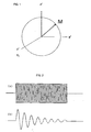
- FIG. 1 is a graph illustrating an example of magnetizing behavior in the rotating coordinate system.
- Figure 2(a) is a chart illustrating an example of a radio frequency pulse which generates a rotating magnetic field (radio frequency magnetic field) B 1
- Figure 2(b) is a chart illustrating an example of a transient nutation signal.
- the nutation signal is observed during an application of the rotating magnetic field (radio frequency magnetic field) B 1
- T n time constant
- longitudinal relaxation time spin-lattice relaxation time
- transverse relaxation time spin-spin relaxation time
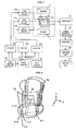
- FIG. 3 is a diagram illustrating one example of a magnetic resonance imaging apparatus according to the present invention.
- This apparatus indicates a case of two-dimensional measurement, and includes a magnet 1 generating a static magnetic field B 0 , and two radio frequency (rotating) magnetic field gradient coils 2x and 2y installed in a position where the static magnetic field exists, as illustrated.
- a sample 3 which is a measuring object is arranged in an approximate center of these.
- the two radio frequency (rotating) magnetic field gradient coils 2x and 2y are arranged so that directions of radio frequency magnetic fields which they generate may be mutually orthogonal and may be orthogonal to the static magnetic field.
- one of the radio frequency magnetic field gradient coils is used as a phase encoding coil, and another radio frequency magnetic field gradient coil is used as a frequency encoding coil.
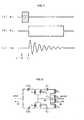
- Figure 4 is a drawing illustrating a structural example of radio frequency magnetic field gradient coils in a two-dimensional imaging method.
- the static magnetic field is arranged as a z-axis
- the phase encoding coil is done as an x-axis
- the frequency encoding coil is done as a y-axis.
- the phase encoding coil 2x is an x gradient coil
- the frequency encoding coil 2y is a y gradient coil. Let a center of these be an origin O.
- the x gradient coil 2x is constructed of a two-turn saddle type coil, and a one-turn saddle type coil opposite to this, that is, a pair of saddle type coils numbers of windings of which are asymmetric.
- dotted lines in a lower portion are lead wires which connect the pair of saddle type coils.
- the y gradient coil 2y is also the same pair of saddle type coils. Lines of magnetic force of a magnetic field gradient which the x gradient coil 2x and the y gradient coil 2y generate are mutually orthogonal.
- Figure 5 includes charts illustrating a pulse sequence in the two-dimensional imaging method
- Figure 5(a) is a chart illustrating an x gradient pulse Gx
- Figure 5(b) is a chart illustrating a y gradient pulse Gy
- Figure 5(c) is a chart illustrating a transient nutation signal TN.
- the radio frequency pulse Gy y gradient pulse
- Phases of the phase encoding pulse GX and the frequency encoding pulse Gy are made to shift by 90° or odd times of 90°.
- a radio frequency oscillator 10 oscillates a radio frequency signal, and a pulse generator 11 generates pulse signals.
- Modulators 12x and 12y modulate radio frequency signals with pulse signals and output them.
- a radio frequency signal whose phase is shifted by, for example, 90° through a phase shifter 13 from the radio frequency oscillator 10 is sent to the modulator 12x.
- Outputs of the modulators 12x and 12y are amplified by the radio frequency amplifiers 14x and 14y respectively, and are supplied to the radio frequency magnetic field gradient coils 2x and 2y as the x gradient pulse Gx and the y gradient pulse Gy as illustrated in Figure 5.
- the transient nutation signal TN is observed.
- the transient nutation signal is included in the frequency encoding pulse with large amplitude as a very weak signal. For this reason, since an amplifier system is saturated when the frequency encoding pulse is amplified directly, the transient nutation signal cannot be observed. Then, in order to remove an unnecessary radio frequency pulse and to detect only a signal, for example, a bridge circuit or a differential circuit is used as the transient nutation signal detector 21.
- FIG. 6 is a diagram illustrating an example of a symmetrical bridge circuit using a differential transformer as a transient nutation signal detector.
- reference numerals CV 1 to CV 4 denote variable capacitors
- reference numerals C 1 to C 3 denote capacitors
- reference numerals L 1 to L 6 denote coils.
- This bridge circuit inputs the radio frequency pulse applied to the frequency encoding coil, subtracts a radio frequency pulse having the same amplitude as this, and takes out only a transient nutation signal included in the frequency encoding pulse as an output.
- this example illustrates a Pake's bridge circuit, it is not limited to this, but, for example, Torrey's symmetrical bridge circuit, and an Anderson's asymmetrical bridge circuit can be also used.
- the transient nutation signal detector 21 can remove the applied radio frequency pulse and can detect only the transient nutation signal. Positional information in an x-axial direction is encoded in a phase of the transient nutation signal observed, and positional information in a y-axial direction is encoded in a frequency.
- the transient nutation signal is transferred to the storage and arithmetic unit 24 through the phase sensitive detector 22 and the amplifier 23. A series of measurement is performed by systematically changing amplitude of the phase encoding pulse, and the transient nutation signal in which the positional information in the x-axial direction is encoded as phase information is stored in the storage and arithmetic unit 24.
- a two-dimensional magnetic resonance image can be obtained by performing two-dimensional Fourier transform processing of the taken-in signal by the same method as a usual Fourier transformation imaging. This can be displayed on the display apparatus 25.
- a static magnetic field gradient and selective excitation can be used for cut-out of a plane perpendicular to the z-axis similarly to a usual magnetic resonance imaging.
- FIG. 7 is a diagram illustrating another example of the magnetic resonance imaging apparatus according to the present invention.
- This apparatus indicates a case of three-dimensional measurement, and includes a magnet 1 generating a static magnetic field B 0 , and three radio frequency (rotating) magnetic field gradient coils 2x, 2y, and 2z installed in a position where the static magnetic field exists, as illustrated.
- a sample 3 which is a measuring object is arranged in an approximate center of these.
- FIG 8 is a drawing illustrating a structural example of radio frequency magnetic field gradient coils in a three-dimensional imaging method.
- a z gradient coil 2z is a pair of saddle type coils with the same numbers of windings. Although its axis is the same as that of the x gradient coil, an upper coil-to-coil distance spreads in comparison with a lower portion of drawing.
- an upper side is longer than a lower side, that is, what the coils envelop becomes an inverted cone instead of a cylinder. Inversion of top and bottom may be also sufficient.
- a radio frequency magnetic field gradient with the gradient in the z-axial direction is generated by a Helmholtz type coil in a broad sense which centers around the x or y axial direction, that is, a coil which is a pair of coils, and in which a gap between the two coils are changed along with the z-axis.
- Figure 9 shows charts illustrating a pulse sequence in the three-dimensional imaging method
- Figure 9(a) is a chart illustrating an x gradient pulse Gx
- Figure 9(b) is a chart illustrating a z gradient pulse Gz
- Figure 9(c) is a chart illustrating a y gradient pulse Gy
- Figure 9(d) is a chart illustrating a transient nutation signal TN.
- a phase of a radio frequency magnetic field is made the same as that of the x gradient pulse, and when it is installed in the y-axial direction, it is made the same phase as that of the y gradient pulse-Phases of the x gradient pulse and the y gradient pulse are made to shift by 90° or odd times of 90°. What is necessary is just to make any one of x, y, and z gradient pulses into a frequency encoding pulse, and to make the two remainings into a phase encoding pulse, and their combination is free.
- a radio frequency oscillator 10 oscillates a radio frequency signal, and a pulse generator 11 generates pulse signals.
- Modulators 12x, 12y, and 12z modulate radio frequency signals with pulse signals and output them.
- a radio frequency signal whose phase is shifted by, for example, 90° through a phase shifter 13 from the radio frequency oscillator 10 is sent to the modulators 12x and 12z.
- Outputs of the modulators 12x, 12y, and 12z are amplified by the radio frequency amplifiers 14x, 14y, and 14z respectively, and are supplied to the radio frequency magnetic field gradient coils 2x, 2y, and 2z as the x gradient pulse GX, the y gradient pulse Gy and the z gradient pulse Gz as illustrated in Figure 9. Thereby, the transient nutation signal TN is observed. Next, this respect will be described in detail.
- the macroscopic magnetization which has been rotating in proportion to the radio frequency magnetic field intensity of the x gradient continues rotation at an angular frequency proportional to the radio frequency magnetic field intensity of the z gradient.
- the macroscopic magnetization continues rotation around the x' axis.
- the transient nutation signal at this time is observed, the positional information in the x- and z-axial direction is encoded in a phase of the signal, and the positional information in the y-axial direction is encoded in its frequency.
- the transient nutation signal at the time of applying the y gradient pulse is observed by the transient nutation signal detector 21 mentioned above.
- the transient nutation signal is transferred to the storage and arithmetic unit 24 through the phase sensitive detector 22 and the amplifier 23.
- a series of transient nutation signals at the time of applying the y gradient pulse are observed by systematically changing amplitude or applying time of the x and z gradient pulses, and this is stored in the storage and arithmetic unit 24.
- a three-dimensional magnetic resonance image can be obtained by performing three-dimensional Fourier transform processing of the taken-in signal by the same method as a usual Fourier transformation imaging. This can be displayed on the display apparatus 25.
- the present invention enables visualization of clearer living body and inter-substance information by the high-speed magnetic resonance imaging without artifact by a distribution of a magnetic susceptibility, a biostimulus by an eddy current, and the like, and can contribute to development of wide fields, such as medicine, medical care, bionics, and physical properties research.
Landscapes
- Physics & Mathematics (AREA)
- Condensed Matter Physics & Semiconductors (AREA)
- General Physics & Mathematics (AREA)
- Optics & Photonics (AREA)
- Spectroscopy & Molecular Physics (AREA)
- High Energy & Nuclear Physics (AREA)
- Magnetic Resonance Imaging Apparatus (AREA)
Applications Claiming Priority (1)
| Application Number | Priority Date | Filing Date | Title |
|---|---|---|---|
| PCT/JP2004/017812 WO2006059378A1 (fr) | 2004-11-30 | 2004-11-30 | Procédé d’imagerie à résonance magnétique et appareil d’imagerie à résonance magnétique |
Publications (1)
| Publication Number | Publication Date |
|---|---|
| EP1832229A1 true EP1832229A1 (fr) | 2007-09-12 |
Family
ID=36564822
Family Applications (1)
| Application Number | Title | Priority Date | Filing Date |
|---|---|---|---|
| EP04822523A Withdrawn EP1832229A1 (fr) | 2004-11-30 | 2004-11-30 | Procede d' imagerie a resonance magnetique et appareil d' imagerie a resonance magnetique |
Country Status (3)
| Country | Link |
|---|---|
| US (1) | US20080042647A1 (fr) |
| EP (1) | EP1832229A1 (fr) |
| WO (1) | WO2006059378A1 (fr) |
Families Citing this family (3)
| Publication number | Priority date | Publication date | Assignee | Title |
|---|---|---|---|---|
| WO2017157872A1 (fr) * | 2016-03-14 | 2017-09-21 | Koninklijke Philips N.V. | Cartographie de susceptibilité d'un sujet en mouvement |
| CN106406329B (zh) * | 2016-11-21 | 2019-06-11 | 哈尔滨工业大学 | 一种基于永磁涡流效应的空间翻滚目标消旋控制方法 |
| CN109250156B (zh) * | 2018-07-24 | 2020-10-16 | 西北工业大学 | 一种空间非合作目标电磁涡流消旋抓捕装置及方法 |
Family Cites Families (7)
| Publication number | Priority date | Publication date | Assignee | Title |
|---|---|---|---|---|
| CA1052861A (fr) * | 1975-03-18 | 1979-04-17 | Varian Associates | Zeugmatographie par resonance gyromagnetique a l'aide de la transformee de fourier |
| US4307343A (en) * | 1979-08-20 | 1981-12-22 | General Electric Company | Moving gradient zeugmatography |
| US4777441A (en) * | 1987-03-23 | 1988-10-11 | Varian Associates, Inc. | Rotating frame zeugmatography |
| JP3375792B2 (ja) * | 1995-07-03 | 2003-02-10 | 株式会社日立製作所 | Rfプローブ及びこれを用いた核磁気共鳴を用いた検査装置 |
| JP3490542B2 (ja) * | 1995-05-31 | 2004-01-26 | 株式会社日立製作所 | 核磁気共鳴を用いた検査装置 |
| JP3702399B2 (ja) * | 1998-01-26 | 2005-10-05 | 株式会社日立メディコ | 磁気共鳴装置 |
| JP2001212104A (ja) * | 2000-02-01 | 2001-08-07 | Hitachi Ltd | 磁気共鳴撮影装置及び受信コイル |
-
2004
- 2004-11-30 WO PCT/JP2004/017812 patent/WO2006059378A1/fr not_active Ceased
- 2004-11-30 EP EP04822523A patent/EP1832229A1/fr not_active Withdrawn
- 2004-11-30 US US11/791,259 patent/US20080042647A1/en not_active Abandoned
Non-Patent Citations (1)
| Title |
|---|
| See references of WO2006059378A1 * |
Also Published As
| Publication number | Publication date |
|---|---|
| WO2006059378A1 (fr) | 2006-06-08 |
| US20080042647A1 (en) | 2008-02-21 |
Similar Documents
| Publication | Publication Date | Title |
|---|---|---|
| US10222438B2 (en) | System and apparatus for combined magnetic resonance imaging with magnetic spectroscopy of brownian motion and/or magnetic nanoparticle imaging | |
| US4516075A (en) | NMR scanner with motion zeugmatography | |
| CN104011557B (zh) | 用于校正mr成像中的主磁场b0的磁场不均匀性的mr设备 | |
| USRE32701E (en) | NMR scanner with motion zeugmatography | |
| US4654591A (en) | NMR flow imaging using bi-phasic excitation field gradients | |
| JPS59132346A (ja) | 核磁気共鳴方法および装置 | |
| Rajan | MRI: a conceptual overview | |
| US20140152303A1 (en) | Magnetic resonance imaging data sampling methods and systems | |
| US20020030491A1 (en) | MRI using multiple RF coils and multiple gradient coils to simultaneously measure multiple samples | |
| CN103454606A (zh) | 用于确定磁共振技术中特定于对象的b1分布的方法 | |
| US4651098A (en) | Method for imaging nuclear magnetic resonance signals by using non-linear magnetic field gradient | |
| JPS62129041A (ja) | 磁気回転共鳴方法及び装置 | |
| JPH02502789A (ja) | 核スピン磁化ベクトル回転法 | |
| EP1832229A1 (fr) | Procede d' imagerie a resonance magnetique et appareil d' imagerie a resonance magnetique | |
| JPH01170446A (ja) | 核磁気共鳴画像診断装置の領域制限方法 | |
| JPS63216557A (ja) | 磁気共鳴映像装置 | |
| JPH01207044A (ja) | 核磁気共鳴画像診断装置の受信装置 | |
| JPH03224538A (ja) | 一次の静磁場不均一を補正して計測する過程を備えたmri装置 | |
| JP3452400B2 (ja) | 磁気共鳴イメージング装置 | |
| JPS61271446A (ja) | フ−リエ・ズ−グマトグラフイにより形成された映像中のア−テイフアクトの減少方法と装置 | |
| JP2005137537A (ja) | 磁気共鳴映像法および磁気共鳴映像装置 | |
| JP5922467B2 (ja) | 磁気共鳴イメージング装置 | |
| JPH0374100B2 (fr) | ||
| JPH04236944A (ja) | Mri装置のqdコイル装置 | |
| JP3274879B2 (ja) | 磁気共鳴イメージング装置 |
Legal Events
| Date | Code | Title | Description |
|---|---|---|---|
| PUAI | Public reference made under article 153(3) epc to a published international application that has entered the european phase |
Free format text: ORIGINAL CODE: 0009012 |
|
| 17P | Request for examination filed |
Effective date: 20070523 |
|
| AK | Designated contracting states |
Kind code of ref document: A1 Designated state(s): DE FR GB |
|
| DAX | Request for extension of the european patent (deleted) | ||
| RBV | Designated contracting states (corrected) |
Designated state(s): DE FR GB |
|
| STAA | Information on the status of an ep patent application or granted ep patent |
Free format text: STATUS: THE APPLICATION IS DEEMED TO BE WITHDRAWN |
|
| 18D | Application deemed to be withdrawn |
Effective date: 20090602 |