EP1832269B1 - Externes kraftkontrollverfahren, externes kraftkontrollsystem und externes kraftkontrollprogramm - Google Patents
Externes kraftkontrollverfahren, externes kraftkontrollsystem und externes kraftkontrollprogramm Download PDFInfo
- Publication number
- EP1832269B1 EP1832269B1 EP05811494.3A EP05811494A EP1832269B1 EP 1832269 B1 EP1832269 B1 EP 1832269B1 EP 05811494 A EP05811494 A EP 05811494A EP 1832269 B1 EP1832269 B1 EP 1832269B1
- Authority
- EP
- European Patent Office
- Prior art keywords
- external force
- motion
- value
- function
- factor
- Prior art date
- Legal status (The legal status is an assumption and is not a legal conclusion. Google has not performed a legal analysis and makes no representation as to the accuracy of the status listed.)
- Expired - Lifetime
Links
Images


Classifications
-
- A—HUMAN NECESSITIES
- A61—MEDICAL OR VETERINARY SCIENCE; HYGIENE
- A61F—FILTERS IMPLANTABLE INTO BLOOD VESSELS; PROSTHESES; DEVICES PROVIDING PATENCY TO, OR PREVENTING COLLAPSING OF, TUBULAR STRUCTURES OF THE BODY, e.g. STENTS; ORTHOPAEDIC, NURSING OR CONTRACEPTIVE DEVICES; FOMENTATION; TREATMENT OR PROTECTION OF EYES OR EARS; BANDAGES, DRESSINGS OR ABSORBENT PADS; FIRST-AID KITS
- A61F2/00—Filters implantable into blood vessels; Prostheses, i.e. artificial substitutes or replacements for parts of the body; Appliances for connecting them with the body; Devices providing patency to, or preventing collapsing of, tubular structures of the body, e.g. stents
- A61F2/50—Prostheses not implantable in the body
- A61F2/68—Operating or control means
- A61F2/70—Operating or control means electrical
- A61F2/72—Bioelectric control, e.g. myoelectric
-
- A—HUMAN NECESSITIES
- A61—MEDICAL OR VETERINARY SCIENCE; HYGIENE
- A61B—DIAGNOSIS; SURGERY; IDENTIFICATION
- A61B5/00—Measuring for diagnostic purposes; Identification of persons
- A61B5/45—For evaluating or diagnosing the musculoskeletal system or teeth
- A61B5/4528—Joints
-
- A—HUMAN NECESSITIES
- A61—MEDICAL OR VETERINARY SCIENCE; HYGIENE
- A61H—PHYSICAL THERAPY APPARATUS, e.g. DEVICES FOR LOCATING OR STIMULATING REFLEX POINTS IN THE BODY; ARTIFICIAL RESPIRATION; MASSAGE; BATHING DEVICES FOR SPECIAL THERAPEUTIC OR HYGIENIC PURPOSES OR SPECIFIC PARTS OF THE BODY
- A61H1/00—Apparatus for passive exercising; Vibrating apparatus; Chiropractic devices, e.g. body impacting devices, external devices for briefly extending or aligning unbroken bones
- A61H1/02—Stretching or bending or torsioning apparatus for exercising
- A61H1/0237—Stretching or bending or torsioning apparatus for exercising for the lower limbs
-
- A—HUMAN NECESSITIES
- A61—MEDICAL OR VETERINARY SCIENCE; HYGIENE
- A61H—PHYSICAL THERAPY APPARATUS, e.g. DEVICES FOR LOCATING OR STIMULATING REFLEX POINTS IN THE BODY; ARTIFICIAL RESPIRATION; MASSAGE; BATHING DEVICES FOR SPECIAL THERAPEUTIC OR HYGIENIC PURPOSES OR SPECIFIC PARTS OF THE BODY
- A61H3/00—Appliances for aiding patients or disabled persons to walk about
Definitions
- the present invention relates to a system for controlling an external force applied to an animal through an orthosis attached to the animal that makes a movement along with the activities of muscle fibers and a program for providing a computer with the control functions.
- An external force applied to a person with the purpose of walking aid is preferably controlled to an appropriate one in relation to an internal force that arises due to his or her will according to the progress of rehabilitation exercise or the like. Therefore, it is conceivable to measure a joint torque on the basis of a myoelectric signal that occurs in a human body and to apply a torque (external force) of an appropriate level according to the joint torque to the person.
- the object of the present invention is to provide a system capable of controlling an external force applied to an animal in such a way as to achieve as a target relation the relation between the external force and a motion variable varying with the motion of the animal and a program for providing a computer with the control functions.
- US 2004/102723 A1 and JP 2004 167056 A disclose devices for applying an external force to a leg to augment the user's own muscle force.
- EP 1324403 A1 discloses a walking assisting device including a myoelectric sensor, a motion analyzer which determines an instant amount of a force exerted by a thigh muscle and an actuator for generating an assisting force which is proportional to the monitored amount of the human force.
- an external force control system for controlling an external force applied to an animal through an orthosis attached to the animal that makes a movement along with the activities of muscle fibers, the system comprising: myoelectric potential measurement means for measuring a myoelectric potential x that occurs in the body of the animal; external force setting means for setting a value of an external force f applied to the animal by a motor through the orthosis according to an external force function f(x)- with the myoelectric potential x as a variable on the basis of the measured value of the myoelectric potential x measured by the myoelectric potential measurement means; motion variable measurement means for measuring a motion variable y varying with the motion of the animal under the condition of the external force applied through the orthosis; factor setting means for setting a value of a factor ⁇ according to a factor function ⁇ (f, y) with the external force f and the motion variable y as variables on the basis of the set value of the external force f set by the external force
- the value of the external force f is set according to the external force function f(x) on the basis of the measured value of the myoelectric potential x and the external force applied to the animal is controlled through the orthosis according to the set value of the external force f.
- the motion variable y varying with the motion of the animal is measured under the condition of the external force applied through the orthosis and the value of the factor ⁇ is set according to a factor function ⁇ (f, y) on the basis of the set value of the external force f and the measured value of the motion variable y.
- a new external force function f(x) is set in such a way that the set value of the factor ⁇ approaches the target value ⁇ t .
- the deviation ⁇ includes a deviation at a certain time point and a mean deviation or cumulative deviation at a plurality of time points or during a continuous time period. This controls the external force f in such a way that the value of the factor ⁇ approaches the target value ⁇ t .
- the factor ⁇ set according to the factor function ⁇ (f, y) with the external force f and the motion variable y as variables represents what kind of relation exists between the external force f and the motion variable y.
- the target value ⁇ t of the factor ⁇ represents what kind of target relation exists between the external force f and the motion variable y.
- the myoelectric potential x can be either one of a myoelectric potential or a combination of a plurality of myoelectric potentials ⁇ x i
- i 1, 2, -- ⁇ .
- the external force f can be either one of an external force or a combination of a plurality of external forces ⁇ f i
- i 1, 2, -- ⁇ .
- the motion variable y can be either one of the motion variable or a combination of a plurality of motion variables ⁇ y i
- i 1, 2, -- ⁇ .
- the factor ⁇ can be either one of a factor or a combination of a plurality of factors ⁇ i
- i 1, 2, -- ⁇ .
- the external force function setting means includes means for setting a value of a coefficient ⁇ that represents the relation between the myoelectric potential x and the external force f and means for setting the external force function f(x) according to a basic function F(x, ⁇ ) with the myoelectric potential x and the coefficient ⁇ as variables on the basis of the set value of the coefficient ⁇ .
- a new value is set for the coefficient ⁇ that represents the relation between the myoelectric potential x and the external force f if the deviation between the set value of the factor ⁇ and its target value ⁇ t is equal to or greater than the reference value ⁇ .
- a new value is set for the external force function f(x) according to the basic function F(x, ⁇ ) on the basis of the new set value of the coefficient ⁇ . Thereafter, the external force f applied to the animal is set according to the new external force function f(x) on the basis of the measured value of the myoelectric potential x.
- the coefficient ⁇ can be either one of a coefficient or a combination of a plurality of coefficients ⁇ i
- i 1, 2, -- ⁇ .
- the external force function setting means includes means for finding the external force target value f t according to the factor function ⁇ (f, y) on the basis of the measured value of the motion variable y and the target value ⁇ t of the factor ⁇ and means for setting the external force function f(x) in such a way that the external force f approaches the external force target value f t .
- the external force function setting means includes means for setting the external force function f(x) in such a way that a maximum measured value of the external force f approaches a maximum value of the external force target value f t .
- the external force f applied to the animal can be controlled in such a way that the maximum measured value of the external force f approaches the maximum value of the target value f t .
- the "maximum value" of the measured value of the external force f and of the target value f t respectively includes the maximum value during a certain time zone and further the maximum value of the measured value of the external force f and of the target value f t in each period in the case of a periodic variation in the measured value of the external force f and in the target value f t .
- the external force function setting means is configured to perform a step of setting a new external force function f(x) when the determination step is omitted after a first external force setting step.
- the new external force function f(x) may be set without passing through the determination in view of the fact that it is highly probable that the first set value of the external force f is far from the target relation between the external force f and the motion variable y since the first external force function f(x) does not yet reflect the actual relation between the external force f and the motion variable y. This enables the external force f to be controlled in such a way that the relation between the external force f and the motion variable y rapidly approaches the target relation.
- the motion variable measurement means includes means for measuring the resultant force of an internal force and an external force of the animal as the motion variable y and the factor setting means includes means for setting the ratio of the external force f to the resultant force of the internal force and the external force of the animal as the factor ⁇ (0 ⁇ 1).
- the motion variable measurement means includes means for measuring a primitive motion variable varying with the motion of the animal and means for measuring the motion variable according to the inverse dynamics model that represents the behaviors of the animal on the basis of the measured value of the primitive motion variable.
- the external force control system further includes a motion state determination means for determining the motion state of the animal according to a given correspondence between the primitive motion variable and the motion state of the animal on the basis of the measured value of the primitive motion variable after measuring the primitive motion variable varying with the motion of the animal, wherein the motion variable measurement means includes means for measuring the motion variable y according to a given correspondence between the motion state of the animal and the motion variable on the basis of the motion state determined in the motion state determination means.
- the external force control system may further include means for measuring the external force f, wherein the factor setting means includes means for setting a value of the factor ⁇ according to the factor function ⁇ (f, y) with the external force f and the motion variable y as variables on the basis of the measured value of the external force f, instead of the set value of the external force f, and the measured value of the motion variable y.
- the factor ⁇ is set on the basis of the measured value of the external force f, and therefore it is possible to control the external force f applied to the animal after removing the effect of the deviation that may occur in the measured value of the external force f from the set value of the external force f.
- the external force control system further includes a motion state determination means for determining the motion state of the animal according to the given correspondence between the primitive motion variable and the motion state of the animal on the basis of the measured value of the primitive motion variable after measuring the primitive motion variable varying with the motion of the animal, wherein the external force function setting means includes means for setting a new external force function f(x) responsive to each motion state determined in the motion state determination means.
- the determination means includes means for determining whether the deviation ⁇ is less than the reference value ⁇ on the basis of the factor target value ⁇ t set for each motion state according to the motion state determined in the motion state determination means and the external force function setting means includes means for setting a new external force function f(x) on the basis of the factor target value ⁇ t set for each motion state according to the motion state determined in the motion state determination means.
- the determination means includes means for determining whether the deviation ⁇ is less than a threshold ⁇ according to the threshold ⁇ depending on whether the deviation ⁇ is positive or negative.
- the external force control system of certain embodiments it is possible to control the external force f in such a way that if the instability level of the motion of the animal undergoing the external force f depends on whether the deviation ⁇ between the set value of the factor ⁇ and its target value ⁇ t is positive or negative, the motion of the animal is stable with consideration given to the difference between them.
- an external force control program for providing a computer with functions for controlling an external force applied to an animal through an orthosis attached to the animal that makes a movement along with the activities of muscle fibers, the program providing a computer with: a myoelectric potential measurement function of measuring a myoelectric potential x that occurs in the body of the animal; an external force setting function of setting a value of an external force f applied to the animal through the orthosis according to an external force function f(x)-with the myoelectric potential x as a variable on the basis of the measured value of the myoelectric potential x; a motion variable measurement function of measuring a motion variable y varying with the motion of the animal under the condition of the external force applied through the orthosis; a factor setting function of setting a value of a factor ⁇ according to a factor function y(f, y) with the external force f and the motion variable y as variables on the basis of the set value of the external force f and
- An external force control system 100 shown in FIG. 1 controls external torques (external forces) around the knee joints of a person (animal) applied to both left and right legs through orthoses 222 attached to the thigh and crus of the legs by means of motors (engines) 220 disposed on the person's left and right knees, respectively.
- the motors 220 work with a battery 200 as a power supply, which is contained in a case 202 attached to the waist.
- the external force control system 100 includes a myoelectric potential measurement unit 110, a resultant force measurement unit (motion variable measurement means) 120, a factor setting unit 130, a determination unit 140, an external force function setting unit 150, an external force setting unit 160, and a motor current control unit 170.
- Each unit is made up of a computer 10 including a CPU as hardware, a memory such as an EEPROM or RAM, an I/O circuit and "an external force control program" of the present invention stored in the memory as software.
- the computer 10 works with the battery 200 as a power supply and is contained in the case 202.
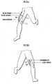
- the myoelectric potential measurement unit 110 measures a myoelectric potential x through extensor surface electrodes 111, each of which are attached to a region of a vastus medialis, a vastus lateralis, and a rectus femoris (extensor) on the surface of the human body as shown in FIG. 2(a) and flexor surface electrodes 112, each of which are attached to a region of a semitendinosus and a biceps femoris (flexor) on the surface of the human body as shown in FIG. 2(b) .
- the resultant force measurement unit 120 includes a chest gyro sensor 121 for outputting a signal responsive to a tilt angular velocity of a human chest, an anteroposterior chest acceleration sensor 122 for outputting a signal responsive to an anteroposterior acceleration of the chest, a waist gyro sensor 123 for outputting a signal responsive to a tilt angular velocity of the waist, an anteroposterior waist acceleration sensor 124 for outputting a signal responsive to an anteroposterior acceleration of the waist, a vertical waist acceleration sensor 125 for outputting a signal responsive to a vertical acceleration of the waist, a hip joint angle sensor 126 for outputting a signal responsive to a flexion angle of a hip joint, and a knee joint angle sensor 127 for outputting a signal responsive to a flexion angle of a knee joint.
- a chest gyro sensor 121 for outputting a signal responsive to a tilt angular velocity of a human chest
- the resultant force measurement unit 120 measures a resultant force F, which is the sum of an internal torque (internal force) around the knee joint that arises in the leg due to the person's will and an external torque (external force) around the knee joint given to the leg by the motor 220 disposed to the knee portion, as "a motion variable” on the basis of outputs from the sensors 121 to 127 and measured values of "primitive motion variables” such as a tilt angular velocity of the human chest or the like by using an inverse dynamics model that represents human behaviors.
- the power of the motor 220 is supplied to each leg through rigid members 224 connected to the motor 220 and extended upwardly and downwardly from the knee portion respectively, supporters (orthoses) 222 connected to the rigid members 224 and attached to the thigh portion and the crus portion, respectively, and a shoe 226 connected to the rigid member 224 extended downwardly from the knee portion.
- the inverse dynamics model is stored in the memory of the computer 10.
- a floor reaction force sensor 128 for outputting a signal responsive to a floor reaction force applied to the sole of foot at the bottom of the shoe 226 with the omission of the sensors 121 to 125 in order to measure the resultant force F according to the inverse dynamics model on the basis of the outputs from the hip joint angle sensor 126, the knee joint angle sensor 127, and the floor reaction force sensor 128.
- the factor setting unit 130 sets the factor ⁇ according to the factor function ⁇ (f, F) with the external force f and the resultant force (motion variable) F as variables on the basis of the set value of the external force f set by the external force setting unit 160 and the measured value of the resultant force F measured by the resultant force measurement unit 120.
- the determination unit 140 determines whether the deviation ⁇ between the measured value of the factor ⁇ and its target value ⁇ t is less than a threshold ⁇ (>0).
- the target value ⁇ t of the factor ⁇ is stored in the memory of the computer 10.
- the target value ⁇ t of the factor ⁇ can be adjusted according to a person's (user's) intention through buttons (not shown) provided in the case 202.
- the external force function setting unit 150 sets an external force target value f t as the product of a measured value of the resultant force F and the factor target value ⁇ t and sets a coefficient ⁇ that represents the relation between the myoelectric potential x and the external force f in such a way that the set value of the external force f is coincident with the external force target value f t .
- the external force function setting unit 150 sets an external force function f(x), which is a function of the myoelectric potential x, according to a basic function F(x, ⁇ , ⁇ ) on the basis of the set value of the factor ⁇ set by the factor setting unit 130 and the set value of the coefficient ⁇ .
- the external force setting unit 160 sets the external force f according to the latest external force function f(x) set by the external force function setting unit 150 on the basis of the measured value of the myoelectric potential x measured by the myoelectric potential measurement unit 110.
- the motor current control unit 170 controls the external force f applied to each leg through the orthosis 222 from the motor 220 by controlling supply current from the battery 200 to the motor 220 according to the set value of the external force f set by the external force setting unit 160.
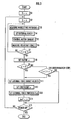
- the following describes the external force control method performed by the external force control system 100 having the above configuration with reference to FIG. 3 and FIG. 4 .
- the control is started by OFF-to-ON switching of an ON/OFF switch (not shown) provided in the case 202.
- the number of times n in setting the external force function f(x) is reset to "0" (S1) and the measurement time t of a timer (not shown) is reset to "0" (S2).
- the myoelectric potential measurement unit 110 measures the value of the myoelectric potential x generated by the activities of the muscle fibers and varied along with the human locomotion or the like through the extensor surface electrodes 111 and the flexor surface electrodes 112 (S3).
- the measured values of the extensor potential x i+ and the flexor potential x j- measured by the myoelectric potential measurement unit 110 are obtained by A/D-converting myoelectric signals detected by the extensor surface electrodes 111 and the flexor surface electrodes 112 after passing through a filter and an amplifier, converting them into absolute values, and passing them through a lowpass filter.
- the first external force function f(x) is preset as shown in the following expression (1) on the basis of the empirical rule or the like and stored in the memory of the computer 10.
- f x h x , ⁇ ⁇ t ⁇ ⁇ i ⁇ i + x i + MA i + + ⁇ j ⁇ j ⁇ x j ⁇ MA j ⁇ ⁇ t
- MA i+ is a moment arm of the extensor, in other words, a distance between the center of rotation of the joint and the position where the extensor is attached to the bone and varies with the flexion angle of the joint.
- MA j- is a moment arm of the flexor, in other words, a distance between the center of rotation of the joint and the position where the flexor is attached to the bone and varies with the flexion angle of the joint.
- the extensor moment arm MA i+ can be supposed to be equivalent to the flexor moment arm MA j- .
- the motor current control unit 170 controls the current I of the motor 220 according to the set value of the external force f set by the external force setting unit 160 (S5). This transmits the power of the motor 220 through the orthosis 222 and applies an external force (an external torque around the knee joint) f coincident with the set value to each human leg.
- the resultant force measurement unit 120 measures the resultant force F, namely, the sum of the internal torque and the external torque around the knee joint by using the inverse dynamics model that represents the human behaviors on the basis of the measured values of the primitive motion variables obtained by the sensors 121 to 127, more specifically, the tilt angle and the anteroposterior acceleration of the chest, the tilt angle of the waist, the anteroposterior acceleration and the vertical acceleration of the waist, the hip joint angle, and the knee joint angle (S6). Since the method of measuring the resultant force F using the inverse dynamics model is available only by adopting a method disclosed in Japanese Patent Laid-Open No. 2003-89083 or the like, its detailed description is omitted here.
- the resultant force F is defined with the direction of knee joint extension or the direction of moving the crus forward as positive.
- the factor setting unit 130 determines whether the timer measurement time t is equal to or greater than given time t n .
- the given time t n can depend on the number of times n in setting the external force function f(x) such that t 0 is longer than t i (i ⁇ 0) or t 0 is shorter than t i (i ⁇ 0) or can be constant independently of the number of times n. If the time t is determined to be less than the given time t n (S7: NO), the measurement of the myoelectric potential x (S3), the setting of the external force f (S4), the control of the motor current (S5), and the measurement of the resultant force F (S6) are performed repeatedly.
- the factor setting unit 130 sets the factor ⁇ according to the factor function ⁇ (f, F) represented by the following expression (2) on the basis of the set value of the external force f (See S4) and the measured value of the resultant force F (See S6) (S8).
- ⁇ f , F f / F
- the factor ⁇ set according to the expression (2) determines the external force f applied to the human leg when the resultant force F is generated and can be referred to as "an assist ratio" because the external force f assists the motion.
- the determination unit 140 determines whether the cumulative number of times n in setting the external force function f(x) is zero (S9). If the number of times n is determined to be zero (S9: YES), the external force function setting unit 150 sets the external force target value f t (S11), sets the coefficient ⁇ that represents the relation between the myoelectric potential x and the external force f (S12), and sets the external force function f(x) (S13).
- the determination unit 140 determines whether or not the deviation ⁇ between the set value of the factor ⁇ and its target value ⁇ t is equal to or greater than the threshold ⁇ (>0) (S10 (determination step)): if the deviation ⁇ is determined to be equal to or greater than the threshold ⁇ (S10: YES), the external force function setting unit 150 sets the external force target value f t (S11), sets the coefficient ⁇ that represents the relation between the myoelectric potential x and the external force f (S12), and sets the external force function f(x) (S13).
- the deviation ⁇ can include a deviation at a single time point and a mean deviation or cumulative deviation at a plurality of time points or during a continuous time period.
- f tmax ⁇ i ⁇ i + x i + MA i + + ⁇ j ⁇ j ⁇ x j ⁇ MA j ⁇ ⁇ t / 1 ⁇ ⁇
- the external force function setting unit 150 sets the external force function f(x) according to the basic function F(x, ⁇ , ⁇ ) represented by the following expression (4) on the basis of the set value of the coefficient ⁇ and the measured value of the factor ⁇ (S13).
- F x , ⁇ , ⁇ h x , ⁇ ⁇ t / 1 ⁇ ⁇ ⁇ ⁇ i ⁇ i + x i + MA i + + ⁇ j ⁇ j ⁇ x j ⁇ MA j ⁇ ⁇ t / 1 ⁇ ⁇
- the setting number of times n is incremented by one (S14). Unless the ON/OFF switch (not shown) is switched from ON to OFF (S15: NO), the timer measurement time t is reset to zero (S2) and the measurement of the myoelectric potential x (S3) and subsequent processing are performed repeatedly.
- the external force function f(x) is set in such a way that the set value of the external force f (See S4) is coincident with the external force target value f t (See S11) if the deviation ⁇ is determined to be equal to or greater than the reference value ⁇ (S10: YES) (S13).
- the external force function f(x) is set according to the basic function F(x, ⁇ , y) (See expression (4)) on the basis of the set value of the factor ⁇ (See S8) that represents the relation between the external force f and the resultant force F and the set value of the coefficient ⁇ (See S12) that represents the relation between the myoelectric potential x and the external force f.
- the first external force function f(x) does not yet reflect the actual relation between the external force f and the resultant force F. Therefore, in view of the fact that it is highly probable that the first set value of the external force f is far from the target relation between the external force f and the resultant force F, the external force function f(x) is set with the omission of the determination step (S10) if the number of times n in setting the external force function f(x) is "0.” This enables the control of the external force f in such a way that the relation between the external force f and the resultant force F rapidly approaches the target relation.
- the animal as a target of the external force control has been a human being.
- the animal can be any of all kinds of animals that make a movement along with the muscle fibers such as mammals including a monkey and a giraffe or fishes.
- the plurality of (three) extensor potentials x i+ and the plurality of (two) flexor potentials x j- have been measured.
- the function h(x, ⁇ ) included in the expressions (1) and (4) in each of these three alternative embodiments can be defined by the following expressions (5) to (7).
- the resultant force measurement unit 120 has measured the resultant force F as a motion variable, in other words, the sum of an internal force (a human voluntary knee joint torque) and the external force (a knee joint torque applied to the human leg) (See S6) on the basis of the outputs from the knee joint angle sensor 127 or the like and the "primitive motion variables" such as the knee joint angle and the angular velocity.
- the resultant force measurement unit 120 can measure the external force F (motion variable) in various methods such as by measuring the external force F based on images captured by a camera (not shown) for taking photographs of human movements.
- the resultant force F which is the sum of the internal torque (internal force) around the knee joint that arises in the leg due to the person's will and the external torque (external force) around the knee joint applied to the leg through the orthoses 222 by the motor 220, has been measured as "the motion variable.”
- the motion variable it is also possible to measure a resultant torque of an internal torque and an external torque around a joint other than a hip joint, an ankle joint, an elbow joint, a shoulder joint and a knee joint, the rate of change in a joint angle such as a knee joint, joint angular velocity, joint angular acceleration, or joint torque, or any combination thereof as "the motion variable.”
- the factor ⁇ can be set according to the factor function ⁇ (f, F) of the external force f and the resultant force F in a different form from the above.
- the set value of the external force f has been used (See S4) at the setting of the factor ⁇ (S8).
- the factor ⁇ is set on the basis of the measured value of the external force f, and therefore it is possible to control the external force f applied to each of the human legs after removing the effect of the deviation that may occur in the measured value of the external force f from the set value of the external force f.
- the factor ⁇ has been set (calculated) whenever the timer measurement time t reaches the given time t n (See S7 and S8).
- the external force control system 100 may include a vertical leg acceleration sensor for outputting a signal responsive to the vertical acceleration of the lower part of the leg and a counter for counting the number of times in the leg reaching the ground on the basis of the output from the vertical leg acceleration sensor, and the factor setting unit 130 may set (calculate) the factor ⁇ whenever the counting number of times with the counter reaches a given number of times.
- the determination step (S10) has been omitted if the number of times n in setting the external force function f(x) is zero. In another embodiment, however, the determination step may be performed independently of the number of times n (even if the number of times n is zero).
- the coefficient ⁇ has been set in such a way that the maximum set value of the external force f is coincident with the maximum value f tmax of the external force target value f t (See S11 and S12). In another embodiment, however, the coefficient ⁇ may be set in such a way that the mean value or cumulative value of the set value of the external force f during a certain time period or at a plurality of time points is coincident with the mean value or cumulative value of the external force target value f t during the certain time period or at the plurality of time points.
- the external force control system 100 may include a motion state determination unit for determining the human motion state on the basis of the output from the hip joint angle sensor 126 and an output from the knee joint angle sensor 127, and the resultant force measurement unit 120 may read (measure) the resultant force F stored in the memory with being associated with the motion state determined by the motion state determination unit on the basis of the motion state.
- the motion state determination unit determines which is the human motion state among a plurality of motion states including "a level walking state” where a person is walking on a level ground or on a sloping ground whose slope is vanishingly gentle, "a downward walking state” where the person is descending stairs or a sloping road, “an upward walking state” where the person is ascending stairs or a sloping road, “a rise-from-chair state” where the person is rising from a chair, and "a sit-on-chair state” where the person is sitting on a chair from a standing position.
- the external force control system 100 may include a motion state determination unit to set the external force function f(x) according to a basic function F(x, ⁇ , ⁇ ) set for each motion state based on the motion state determined by the motion state determination unit and stored in the memory (S12).
- the external force control system 100 may include a motion state determination unit, the determination unit 140 may make determination on the basis of the factor target value ⁇ t set for each motion state based on the motion state determined by the motion state determination unit and stored in the memory (S10), and the external force function setting unit 150 may set the external force function f(x) after setting the coefficient ⁇ on the basis of the factor target value ⁇ t set for each motion state according to the motion state determined by the motion state determination unit (S11, S12).
- the determination unit 140 may determine whether the deviation ⁇ is less than the threshold ⁇ according to the threshold ⁇ that depends on the difference between positive or negative in the deviation ⁇ . According to another embodiment described above, it is possible to control the external force f in such a way that if the instability level of the motion of the animal undergoing the external force f depends on whether the deviation ⁇ between the set value of the factor ⁇ and its target value ⁇ t is positive or negative, the motion of the animal is stable with consideration given to the difference between them.
Landscapes
- Health & Medical Sciences (AREA)
- Life Sciences & Earth Sciences (AREA)
- Veterinary Medicine (AREA)
- Animal Behavior & Ethology (AREA)
- General Health & Medical Sciences (AREA)
- Public Health (AREA)
- Physical Education & Sports Medicine (AREA)
- Rehabilitation Therapy (AREA)
- Pain & Pain Management (AREA)
- Epidemiology (AREA)
- Heart & Thoracic Surgery (AREA)
- Oral & Maxillofacial Surgery (AREA)
- Biomedical Technology (AREA)
- Engineering & Computer Science (AREA)
- Physics & Mathematics (AREA)
- Molecular Biology (AREA)
- Pathology (AREA)
- Rheumatology (AREA)
- Orthopedic Medicine & Surgery (AREA)
- Dentistry (AREA)
- Medical Informatics (AREA)
- Biophysics (AREA)
- Surgery (AREA)
- Cardiology (AREA)
- Transplantation (AREA)
- Vascular Medicine (AREA)
- Rehabilitation Tools (AREA)
- Manipulator (AREA)
- Measurement And Recording Of Electrical Phenomena And Electrical Characteristics Of The Living Body (AREA)
Claims (13)
- System zum Steuern einer äußeren Kraft (100) zum Steuern einer äußeren Kraft, die auf ein Tier durch eine Orthese (222) ausgeübt wird, die am Tier angebracht ist, die eine Bewegung gemeinsam mit den Aktivitäten von Muskelfasern ausführt, das System umfassend:Mittel zum Messen eines myoelektrischen Potentials (110) zum Messen eines myoelektrischen Potentials x, das im Körper des Tiers auftritt;Mittel zum Einstellen einer äußeren Kraft (160) zum Einstellen eines Werts einer äußeren Kraft f, die durch einen Motor über die Orthese auf das Tier ausgeübt wird, nach einer Funktion der äußeren Kraft f(x) - mit dem myoelektrischen Potential x als Variable auf der Basis des Messwerts des myoelektrischen Potentials x, das durch das Mittel zum Messen des myoelektrischen Potentials (110) gemessen wird;Mittel zum Messen einer Bewegungsvariable (120) zum Messen einer Bewegungsvariable y, die mit der Bewegung des Tiers variiert, unter der Bedingung, dass die äußere Kraft über die Orthese ausgeübt wird;Faktoreinstellungsmittel (130) zum Einstellen eines Werts eines Faktors y gemäß einer Faktorfunktion γ(f, γ), mit der äußeren Kraft f und der Bewegungsvariable γ als Variable, auf der Basis des Sollwerts der äußeren Kraft f, der durch das Mittel zum Einstellen einer äußeren Kraft (160) eingestellt ist, und des Messwerts der Bewegungsvariable y, der durch das Mittel zum Messen einer Bewegungsvariable (120) gemessen wird;Bestimmungsmittel (140) zum Bestimmen, ob eine Abweichung δ zwischen dem Sollwert des Faktors γ, der durch das Faktoreinstellungsmittel (130) eingestellt wird, und einem Zielwert γt desselben kleiner ist als ein Referenzwert ε;Mittel zum Einstellen einer äußeren Kraftfunktion (150) zum Einstellen einer neuen äußeren Kraftfunktion f(x) in derartiger Weise, dass sich der Sollwert des Faktors γ dem Zielwert γt nähert, falls durch das Bestimmungsmittel (140) bestimmt wird, dass die Abweichung δ gleich oder größer als der Referenzwert ε ist; undMotorstromsteuermittel (170) zum Steuern der äußeren Kraft, die auf das Tier ausgeübt wird, durch Steuern eines Versorgungsstroms von einer Batterie (200) zum Motor (220) nach einem Sollwert der äußeren Kraft f, der durch das Mittel zum Einstellen einer äußeren Kraft (160) eingestellt wird.
- System zum Steuern einer äußeren Kraft (100) nach Anspruch 1, wobei das Mittel zum Einstellen einer äußeren Kraftfunktion (150) Mittel umfasst, die konfiguriert sind, einen Wert eines Koeffizienten α einzustellen, der die Relation zwischen dem myoelektrischen Potential x, gemessen durch das Mittel zum Messen eines myoelektrischen Potentials (110), und der äußeren Kraft f, eingestellt durch das Mittel zum Einstellen einer äußeren Kraft (160), darstellt, sowie Mittel, die konfiguriert sind, die äußere Kraftfunktion f(x) nach einer Grundfunktion F(x, a), mit dem myoelektrischen Potential x und dem Koeffizienten α als Variable, auf der Basis des Sollwerts des Koeffizienten α einzustellen.
- System zum Steuern einer äußeren Kraft (100) nach Anspruch 1, wobei das Mittel zum Einstellen einer äußeren Kraftfunktion (160) Mittel umfasst, die konfiguriert sind, den Zielwert einer äußeren Kraft ft nach der Faktorfunktion γ(f, γ) auf der Basis des Messwerts der Bewegungsvariable y, gemessen durch das Mittel zum Messen einer Bewegungsvariable (120), und des Zielwerts γt des Faktors γ, eingestellt durch das Faktoreinstellungsmittel (130) zu finden, und Mittel, die konfiguriert sind, die äußere Kraftfunktion f(x) in derartiger Weise einzustellen, dass sich die äußere Kraft f, die durch das Mittel zum Einstellen einer äußeren Kraft (160) eingestellt wird, dem Zielwert der äußeren Kraft ft nähert.
- System zum Steuern einer äußeren Kraft (100) nach Anspruch 3, wobei das Mittel zum Einstellen einer äußeren Kraftfunktion (160) Mittel umfasst, die konfiguriert sind, die äußere Kraftfunktion f(x) in derartiger Weise einzustellen, dass sich der maximale Messwert der äußeren Kraft f, eingestellt durch das Mittel zum Einstellen einer äußeren Kraft (160) dem maximalen Wert des Zielwerts der äußeren Kraft ft nähert.
- System zum Steuern einer äußeren Kraft (100) nach Anspruch 1, wobei das Mittel zum Einstellen einer äußeren Kraftfunktion (150) konfiguriert ist, einen Schritt zum Einstellen einer neuen äußeren Kraftfunktion f(x) durchzuführen, wenn der Bestimmungsschritt nach einem ersten Einstellungsschritt einer äußeren Kraft unterlassen wird.
- System zum Steuern einer äußeren Kraft (100) nach Anspruch 1, wobei:das Mittel zum Messen einer Bewegungsvariable (120) Mittel umfasst, die konfiguriert sind, die resultierende Kraft einer inneren Kraft und einer äußeren Kraft des Tiers als Bewegungsvariable γ zu messen; unddas Faktoreinstellungsmittel (130) Mittel umfasst, die konfiguriert sind, das Verhältnis der äußeren Kraft f zur resultierenden Kraft der inneren Kraft und der äußeren Kraft des Tiers als den Faktor γ (0 ≤ γ < 1) einzustellen.
- System zum Steuern einer äußeren Kraft (100) nach Anspruch 1, wobei das Mittel zum Messen einer Bewegungsvariable (120) Mittel umfasst, die konfiguriert sind, eine primitive Bewegungsvariable zu messen, die mit der Bewegung des Tiers variiert, und Mittel, die konfiguriert sind, die Bewegungsvariable nach einem inversen Dynamikmodell zu messen, das das Verhalten des Tiers auf der Basis des Messwerts der primitiven Modellvariable darstellt.
- System zum Steuern einer äußeren Kraft (100) nach Anspruch 1, weiter umfassend ein Bewegungszustandsbestimmungsmittel, das konfiguriert ist, den Bewegungszustand des Tiers nach einer gegebenen Entsprechung zwischen der primitiven Bewegungsvariable und dem Bewegungszustand des Tiers auf der Basis des Messwerts der primitiven Bewegungsvariable nach Messen der primitiven Bewegungsvariable, die mit der Bewegung des Tiers variiert, zu bestimmen, wobei das Mittel zum Messen einer Bewegungsvariable (120) Mittel umfasst, die konfiguriert sind, die Bewegungsvariable γ nach einer gegebenen Entsprechung zwischen dem Bewegungszustand des Tiers und der Bewegungsvariable auf der Basis des Bewegungszustands zu messen, der im Bewegungszustandsbestimmungsmittel bestimmt wird.
- System zum Steuern einer äußeren Kraft (100) nach Anspruch 1, weiter umfassend ein Mittel, das konfiguriert ist, die externe Kraft f zu messen, wobei das Faktoreinstellungsmittel (130) Mittel umfasst, die konfiguriert sind, einen Wert des Faktors γ nach der Faktorfunktion γ(f, y), mit der äußeren Kraft f und der Bewegungsvariable γ als Variable, auf der Basis des Messwerts der äußeren Kraft f, anstelle des Sollwerts der äußeren Kraft f, und des Messwerts der Bewegungsvariable y einzustellen.
- System zum Steuern einer äußeren Kraft (100) nach Anspruch 1, weiter umfassend ein Bewegungszustandsbestimmungsmittel, das konfiguriert ist, den Bewegungszustand des Tiers nach einer gegebenen Entsprechung zwischen der primitiven Bewegungsvariable und dem Bewegungszustand des Tiers auf der Basis des Messwerts der primitiven Bewegungsvariable nach Messen der primitiven Bewegungsvariable, die mit der Bewegung des Tiers variiert, zu bestimmen, wobei das Mittel zum Einstellen einer äußeren Kraftfunktion (150) Mittel umfasst, die konfiguriert sind, eine neue äußere Kraftfunktion f(x) in Reaktion auf jeden Bewegungszustand, der im Bewegungszustandsbestimmungsmittel bestimmt wird, einzustellen.
- System zum Steuern einer äußeren Kraft (100) nach Anspruch 10, wobei:das Bestimmungsmittel (140) Mittel umfasst, die konfiguriert sind, auf der Basis des Faktorzielwerts γt, der für jeden Bewegungszustand gemäß dem Bewegungszustand eingestellt ist, der im Bewegungszustandsbestimmungsmittel bestimmt wird, zu bestimmen, ob die Abweichung δ kleiner als der Referenzwert ε ist; unddas Mittel zum Einstellen einer äußeren Kraftfunktion (150) Mittel umfasst, die konfiguriert sind, eine neue äußere Kraftfunktion f(x) auf der Basis des Faktorzielwerts γt, der für jeden Bewegungszustand nach dem Bewegungszustand eingestellt ist, der im Bewegungszustandsbestimmungsmittel bestimmt wird, einzustellen.
- System zum Steuern einer äußeren Kraft (100) nach Anspruch 1, wobei das Bestimmungsmittel (140) Mittel umfasst, die konfiguriert sind, nach einem Schwellenwert ε zu bestimmen, ob die Abweichung δ kleiner als der Schwellenwert ε ist, abhängig davon, ob die Abweichung δ positiv oder negativ ist.
- Programm zum Steuern einer äußeren Kraft zum Bereitstellen von Funktionen für einen Computer zum Steuern einer äußeren Kraft, die auf ein Tier durch eine Orthese (222) ausgeübt wird, die am Tier angebracht ist, die eine Bewegung gemeinsam mit den Aktivitäten von Muskelfasern ausführt, wobei das Programm dem Computer bereitstellt:eine Funktion zum Messen eines myoelektrischen Potentials zum Messen eines myoelektrischen Potentials x, das im Körper des Tiers auftritt;eine Funktion zum Einstellen einer äußeren Kraft zum Einstellen eines Werts einer äußeren Kraft f, die durch die Orthese auf das Tier ausgeübt wird, nach einer Funktion der äußeren Kraft f(x) - mit dem myoelektrischen Potential x als Variable auf der Basis des Messwerts des myoelektrischen Potentials x;eine Funktion zum Messen einer Bewegungsvariable zum Messen einer Bewegungsvariable y, die mit der Bewegung des Tiers variiert, unter der Bedingung, dass die äußere Kraft über die Orthese ausgeübt wird;eine Faktoreinstellungsfunktion zum Einstellen eines Werts eines Faktors γ nach einer Faktorfunktion γ(f, y), mit der äußeren Kraft f und der Bewegungsvariable y als Variable, auf der Basis des Sollwerts der äußeren Kraft f und des Messwerts der Bewegungsvariable y;eine Bestimmungsfunktion zum Bestimmen, ob eine Abweichung δ zwischen dem Sollwert des Faktors γ und einem Zielwert γt desselben kleiner ist als ein Referenzwert ε; undeine Funktion zum Einstellen einer äußeren Kraftfunktion zum Einstellen einer neuen äußeren Kraftfunktion f(x) in derartiger Weise, dass sich der Sollwert des Faktors γ dem Zielwert γt nähert, falls durch die Bestimmungsfunktion bestimmt wird, dass die Abweichung δ gleich oder größer als der Referenzwert ε ist.
Applications Claiming Priority (2)
| Application Number | Priority Date | Filing Date | Title |
|---|---|---|---|
| JP2004365056A JP4541867B2 (ja) | 2004-12-16 | 2004-12-16 | 外力制御方法、外力制御システム及び外力制御プログラム |
| PCT/JP2005/021879 WO2006064657A1 (ja) | 2004-12-16 | 2005-11-29 | 外力制御方法、外力制御システム及び外力制御プログラム |
Publications (3)
| Publication Number | Publication Date |
|---|---|
| EP1832269A1 EP1832269A1 (de) | 2007-09-12 |
| EP1832269A4 EP1832269A4 (de) | 2016-03-02 |
| EP1832269B1 true EP1832269B1 (de) | 2019-01-09 |
Family
ID=36587716
Family Applications (1)
| Application Number | Title | Priority Date | Filing Date |
|---|---|---|---|
| EP05811494.3A Expired - Lifetime EP1832269B1 (de) | 2004-12-16 | 2005-11-29 | Externes kraftkontrollverfahren, externes kraftkontrollsystem und externes kraftkontrollprogramm |
Country Status (4)
| Country | Link |
|---|---|
| US (1) | US7860562B2 (de) |
| EP (1) | EP1832269B1 (de) |
| JP (1) | JP4541867B2 (de) |
| WO (1) | WO2006064657A1 (de) |
Families Citing this family (61)
| Publication number | Priority date | Publication date | Assignee | Title |
|---|---|---|---|---|
| US7774177B2 (en) * | 2001-06-29 | 2010-08-10 | Honda Motor Co., Ltd. | Exoskeleton controller for a human-exoskeleton system |
| US6996558B2 (en) | 2002-02-26 | 2006-02-07 | International Business Machines Corporation | Application portability and extensibility through database schema and query abstraction |
| US7900133B2 (en) | 2003-12-09 | 2011-03-01 | International Business Machines Corporation | Annotation structure type determination |
| US8082062B2 (en) * | 2005-06-10 | 2011-12-20 | Honda Motor Co., Ltd. | Regenerative actuation in motion control |
| US8849457B2 (en) | 2006-07-17 | 2014-09-30 | Raytheon Company | Contact displacement actuator system |
| US8585620B2 (en) | 2006-09-19 | 2013-11-19 | Myomo, Inc. | Powered orthotic device and method of using same |
| US10758394B2 (en) | 2006-09-19 | 2020-09-01 | Myomo, Inc. | Powered orthotic device and method of using same |
| JP5557529B2 (ja) * | 2006-09-19 | 2014-07-23 | マイオモ インコーポレイテッド | 動力で作動する矯正デバイス |
| US7717826B2 (en) * | 2007-03-21 | 2010-05-18 | Ut-Battelle, Llc | Electrical signature analysis to quantify human and animal performance on fitness and therapy equipment such as a treadmill |
| US8117047B1 (en) | 2007-04-16 | 2012-02-14 | Insight Diagnostics Inc. | Healthcare provider organization |
| US20110082566A1 (en) * | 2008-09-04 | 2011-04-07 | Herr Hugh M | Implementing a stand-up sequence using a lower-extremity prosthesis or orthosis |
| US8096965B2 (en) * | 2008-10-13 | 2012-01-17 | Argo Medical Technologies Ltd. | Locomotion assisting device and method |
| WO2011055428A1 (ja) * | 2009-11-04 | 2011-05-12 | トヨタ自動車株式会社 | 歩行補助装置 |
| EP2500007B1 (de) * | 2009-11-13 | 2018-12-26 | Toyota Jidosha Kabushiki Kaisha | Gehhilfevorrichtung |
| JP5083463B2 (ja) | 2010-03-25 | 2012-11-28 | トヨタ自動車株式会社 | 歩行補助装置 |
| JP5588724B2 (ja) * | 2010-04-23 | 2014-09-10 | 本田技研工業株式会社 | 歩行運動補助装置 |
| ES2636946T3 (es) | 2010-09-27 | 2017-10-10 | Vanderbilt University | Dispositivo de asistencia al movimiento |
| US9682006B2 (en) * | 2010-09-27 | 2017-06-20 | Vanderbilt University | Movement assistance devices |
| US9295576B2 (en) * | 2010-09-28 | 2016-03-29 | Orthocare Innovations Llc | Computerized orthotic prescription system |
| US20120184871A1 (en) * | 2011-01-14 | 2012-07-19 | Seungjin Jang | Exercise monitor and method for monitoring exercise |
| US9789603B2 (en) | 2011-04-29 | 2017-10-17 | Sarcos Lc | Teleoperated robotic system |
| JP5849657B2 (ja) * | 2011-11-30 | 2016-02-03 | 大日本印刷株式会社 | 測定装置、動作補助ロボット、測定方法、および、測定装置用プログラム |
| US9616580B2 (en) | 2012-05-14 | 2017-04-11 | Sarcos Lc | End effector for a robotic arm |
| KR20150077413A (ko) | 2012-09-17 | 2015-07-07 | 프레지던트 앤드 펠로우즈 오브 하바드 칼리지 | 인간의 움직임에 대한 보조를 위한 소프트 엑소슈트 |
| US10843332B2 (en) | 2013-05-31 | 2020-11-24 | President And Fellow Of Harvard College | Soft exosuit for assistance with human motion |
| KR20150039386A (ko) * | 2013-10-02 | 2015-04-10 | 삼성전자주식회사 | 보행 보조 장치 및 보행 보조 장치의 제어방법 |
| US9474634B2 (en) | 2013-10-22 | 2016-10-25 | Massachusetts Institute Of Technology | Peripheral neural interface via nerve regeneration to distal tissues |
| US20150148708A1 (en) * | 2013-11-27 | 2015-05-28 | Oregon Health & Science University | Biofeedback during assisted movement rehabilitation therapy |
| WO2015088863A2 (en) | 2013-12-09 | 2015-06-18 | President And Fellows Of Harvard College | Assistive flexible suits, flexible suit systems, and methods for making and control thereof to assist human mobility |
| EP3102171A4 (de) | 2014-02-05 | 2018-03-28 | President and Fellows of Harvard College | Systeme, verfahren und vorrichtung zur unterstützung des gehens für kleinkinder mit verzögerter entwicklung |
| US10864100B2 (en) | 2014-04-10 | 2020-12-15 | President And Fellows Of Harvard College | Orthopedic device including protruding members |
| US10766133B2 (en) | 2014-05-06 | 2020-09-08 | Sarcos Lc | Legged robotic device utilizing modifiable linkage mechanism |
| CN106795868B (zh) | 2014-09-19 | 2020-05-12 | 哈佛大学校长及研究员协会 | 用于人类运动辅助的软外套 |
| JP6483419B2 (ja) * | 2014-12-01 | 2019-03-13 | トヨタ自動車株式会社 | 荷重判定方法 |
| JP6479512B2 (ja) * | 2015-03-11 | 2019-03-06 | 株式会社東芝 | 動作支援装置 |
| WO2016161457A1 (en) * | 2015-04-03 | 2016-10-06 | Guerrier Chadley | Dynamic injury protection system |
| JP2018519004A (ja) | 2015-06-15 | 2018-07-19 | マイオモ インコーポレイテッド | 電動矯正デバイスおよびそれを使用する方法 |
| US11179251B2 (en) | 2016-01-08 | 2021-11-23 | Massachusetts Institute Of Technology | Method and system for providing proprioceptive feedback and functionality mitigating limb pathology |
| US11590046B2 (en) | 2016-03-13 | 2023-02-28 | President And Fellows Of Harvard College | Flexible members for anchoring to the body |
| KR101836636B1 (ko) | 2016-05-19 | 2018-03-09 | 현대자동차주식회사 | 착용식 보행 보조 로봇 시스템 및 그 제어 방법 |
| EP3487666B1 (de) | 2016-07-22 | 2024-11-13 | President and Fellows of Harvard College | Bedienelementeoptimierung für wearable-systeme |
| US11801153B2 (en) * | 2016-07-29 | 2023-10-31 | The United States Of America, As Represented By The Secretary, Department Of Health And Human Services | Powered gait assistance systems |
| US10765537B2 (en) | 2016-11-11 | 2020-09-08 | Sarcos Corp. | Tunable actuator joint modules having energy recovering quasi-passive elastic actuators for use within a robotic system |
| US10919161B2 (en) | 2016-11-11 | 2021-02-16 | Sarcos Corp. | Clutched joint modules for a robotic system |
| US10828767B2 (en) | 2016-11-11 | 2020-11-10 | Sarcos Corp. | Tunable actuator joint modules having energy recovering quasi-passive elastic actuators with internal valve arrangements |
| US10821614B2 (en) | 2016-11-11 | 2020-11-03 | Sarcos Corp. | Clutched joint modules having a quasi-passive elastic actuator for a robotic assembly |
| WO2018170170A1 (en) | 2017-03-14 | 2018-09-20 | President And Fellows Of Harvard College | Systems and methods for fabricating 3d soft microstructures |
| CN107661193B (zh) * | 2017-09-20 | 2020-04-07 | 深圳市行者机器人技术有限公司 | 一种助行靴 |
| US10843330B2 (en) | 2017-12-07 | 2020-11-24 | Sarcos Corp. | Resistance-based joint constraint for a master robotic system |
| US11331809B2 (en) | 2017-12-18 | 2022-05-17 | Sarcos Corp. | Dynamically controlled robotic stiffening element |
| US11241801B2 (en) | 2018-12-31 | 2022-02-08 | Sarcos Corp. | Robotic end effector with dorsally supported actuation mechanism |
| US10906191B2 (en) | 2018-12-31 | 2021-02-02 | Sarcos Corp. | Hybrid robotic end effector |
| US11351675B2 (en) | 2018-12-31 | 2022-06-07 | Sarcos Corp. | Robotic end-effector having dynamic stiffening elements for conforming object interaction |
| CN111419644B (zh) * | 2020-06-09 | 2020-09-29 | 上海神泰医疗科技有限公司 | 康复机器人的操作方法、康复机器人及可读存储介质 |
| US11833676B2 (en) | 2020-12-07 | 2023-12-05 | Sarcos Corp. | Combining sensor output data to prevent unsafe operation of an exoskeleton |
| US11794345B2 (en) | 2020-12-31 | 2023-10-24 | Sarcos Corp. | Unified robotic vehicle systems and methods of control |
| US11826907B1 (en) | 2022-08-17 | 2023-11-28 | Sarcos Corp. | Robotic joint system with length adapter |
| US11717956B1 (en) | 2022-08-29 | 2023-08-08 | Sarcos Corp. | Robotic joint system with integrated safety |
| US12172298B2 (en) | 2022-11-04 | 2024-12-24 | Sarcos Corp. | Robotic end-effector having dynamic stiffening elements with resilient spacers for conforming object interaction |
| US11924023B1 (en) | 2022-11-17 | 2024-03-05 | Sarcos Corp. | Systems and methods for redundant network communication in a robot |
| US11897132B1 (en) | 2022-11-17 | 2024-02-13 | Sarcos Corp. | Systems and methods for redundant network communication in a robot |
Citations (1)
| Publication number | Priority date | Publication date | Assignee | Title |
|---|---|---|---|---|
| EP1324403A1 (de) * | 2001-12-28 | 2003-07-02 | Matsushita Electric Works, Ltd. | Tragbarer Antriebsaktuator für Bewegungen des menschlichen Körpers |
Family Cites Families (28)
| Publication number | Priority date | Publication date | Assignee | Title |
|---|---|---|---|---|
| US2239223A (en) * | 1938-11-03 | 1941-04-22 | Gilman Martin John | Blocking armor |
| US3418662A (en) * | 1965-03-31 | 1968-12-31 | Nat Res Dev | Prosthetic hand with improved control system for activation by electromyogram signals |
| USD245731S (en) * | 1975-07-23 | 1977-09-13 | Bargsten Betty J | Chest protector for motorcycle riders |
| US4497069A (en) * | 1983-01-20 | 1985-02-05 | Braunhut Harold N | Universally fitting, modular ballistic garment |
| USD340542S (en) * | 1991-10-17 | 1993-10-19 | Nicholas Marlowe | Protective vest |
| US5413611A (en) * | 1992-07-21 | 1995-05-09 | Mcp Services, Inc. | Computerized electronic prosthesis apparatus and method |
| USD441917S1 (en) * | 1997-07-15 | 2001-05-08 | Med-Eng Systems, Inc. | Protective body suit |
| USD429384S (en) * | 1997-10-15 | 2000-08-08 | Med. Eng Systems Inc. | Protective body suit |
| US5966747A (en) * | 1998-04-30 | 1999-10-19 | Med-Eng Systems Inc. | Protective suit with groin protector |
| USD435697S (en) * | 1999-02-22 | 2000-12-26 | Med-Eng Systems Inc. | Set of protective clothing |
| JP2001286451A (ja) | 2000-04-07 | 2001-10-16 | Rikogaku Shinkokai | 筋電信号の正規化基準値算出方法、内的力基準値算出方法、収縮度算出方法、内的力算出方法及びこれらの装置 |
| US6360372B2 (en) * | 2000-06-19 | 2002-03-26 | Joseph Oster | Shirt with adjustable sleeves |
| US6660042B1 (en) * | 2001-02-02 | 2003-12-09 | Rutgers, The State University Of New Jersey | Methods of biomimetic finger control by filtering of distributed forelimib pressures |
| EP1252871A1 (de) * | 2001-03-30 | 2002-10-30 | I.N.A.I.L. Centro per la Sperimentazione ed Applicazione di Protesi e Presidi Ortopedici per Gli Informtuni Sul Lavoro | System zum Kontrollieren und Überwachen von Fuktionsvorrichtungen für Invaliden mit energie von ausserhalb des Körpers und Verfaheren für deren Fernkontrolle |
| USD476138S1 (en) * | 2001-05-21 | 2003-06-24 | The Chief Constable Of Hertfordshire Constabulary | Garment combining body armour and outer shell |
| JP4611580B2 (ja) * | 2001-06-27 | 2011-01-12 | 本田技研工業株式会社 | トルク付与システム |
| JP4188607B2 (ja) * | 2001-06-27 | 2008-11-26 | 本田技研工業株式会社 | 二足歩行移動体の床反力推定方法及び二足歩行移動体の関節モーメント推定方法 |
| US6698024B2 (en) * | 2001-08-10 | 2004-03-02 | Point Blank Body Armor, Inc. | Modular front opening body armor |
| USD475812S1 (en) * | 2001-08-14 | 2003-06-10 | Med-Eng Systems, Inc. | Bomb disposal suit |
| JP3833921B2 (ja) * | 2001-10-18 | 2006-10-18 | 本田技研工業株式会社 | 歩行状態判定装置及び方法 |
| JP3930399B2 (ja) * | 2002-08-21 | 2007-06-13 | 本田技研工業株式会社 | 歩行補助装置 |
| JP2004105261A (ja) * | 2002-09-13 | 2004-04-08 | Matsushita Electric Ind Co Ltd | 身体装着型パワーアシスト機器 |
| US6971267B2 (en) * | 2002-09-23 | 2005-12-06 | Honda Giken Kogyo Kabushiki Kaisha | Method and processor for obtaining moments and torques in a biped walking system |
| US7396337B2 (en) * | 2002-11-21 | 2008-07-08 | Massachusetts Institute Of Technology | Powered orthotic device |
| JP2004167056A (ja) * | 2002-11-21 | 2004-06-17 | Yaskawa Electric Corp | 歩行訓練装置 |
| US6966882B2 (en) * | 2002-11-25 | 2005-11-22 | Tibion Corporation | Active muscle assistance device and method |
| US6961957B2 (en) * | 2003-04-15 | 2005-11-08 | Safari Land Ltd., Inc. | Energy absorbing device for ballistic body armor |
| JP4178186B2 (ja) * | 2003-08-21 | 2008-11-12 | 国立大学法人 筑波大学 | 装着式動作補助装置、装着式動作補助装置の制御方法および制御用プログラム |
-
2004
- 2004-12-16 JP JP2004365056A patent/JP4541867B2/ja not_active Expired - Fee Related
-
2005
- 2005-11-29 EP EP05811494.3A patent/EP1832269B1/de not_active Expired - Lifetime
- 2005-11-29 WO PCT/JP2005/021879 patent/WO2006064657A1/ja not_active Ceased
- 2005-11-29 US US10/599,808 patent/US7860562B2/en not_active Expired - Fee Related
Patent Citations (1)
| Publication number | Priority date | Publication date | Assignee | Title |
|---|---|---|---|---|
| EP1324403A1 (de) * | 2001-12-28 | 2003-07-02 | Matsushita Electric Works, Ltd. | Tragbarer Antriebsaktuator für Bewegungen des menschlichen Körpers |
Also Published As
| Publication number | Publication date |
|---|---|
| JP2006167223A (ja) | 2006-06-29 |
| EP1832269A1 (de) | 2007-09-12 |
| US20080139968A1 (en) | 2008-06-12 |
| EP1832269A4 (de) | 2016-03-02 |
| JP4541867B2 (ja) | 2010-09-08 |
| US7860562B2 (en) | 2010-12-28 |
| WO2006064657A1 (ja) | 2006-06-22 |
Similar Documents
| Publication | Publication Date | Title |
|---|---|---|
| EP1832269B1 (de) | Externes kraftkontrollverfahren, externes kraftkontrollsystem und externes kraftkontrollprogramm | |
| CN1929805B (zh) | 安装式动作辅助装置、安装式动作辅助装置的校准装置以及校准方法 | |
| US8932241B2 (en) | Wearable action-assist device and control program | |
| US7713217B2 (en) | Torque imparting system | |
| EP2827809B1 (de) | Mensch-maschine-schnittstelle für orthesen der unteren extremitäten | |
| JP4178185B2 (ja) | 装着式動作補助装置、及び装着式動作補助装置における駆動源の制御方法、及びプログラム | |
| EP2663267B1 (de) | Angetriebene gelenkorthese | |
| KR102503955B1 (ko) | 밸런스 제어 방법 및 장치 | |
| US20060004299A1 (en) | Motion measurement method, motion measurement system, and motion measurement program | |
| Xia et al. | Design of a multi-functional soft ankle exoskeleton for foot-drop prevention, propulsion assistance, and inversion/eversion stabilization | |
| JP5108922B2 (ja) | 装着式動作補助装置及びその制御方法 | |
| CN106264988A (zh) | 外骨骼踝关节机器装置 | |
| JP2002301124A (ja) | 歩行補助装置 | |
| Moltedo et al. | Walking with a powered ankle-foot orthosis: the effects of actuation timing and stiffness level on healthy users | |
| Lenzi et al. | Reducing muscle effort in walking through powered exoskeletons | |
| JP4601691B2 (ja) | 装着式動作補助装置のキャリブレーション装置、及びキャリブレーション用プログラム | |
| KR20190142709A (ko) | 하지 보조로봇의 제어방법 | |
| JP2025000519A (ja) | 歩行補助装置、制御装置、及び制御プログラム | |
| Matsuda et al. | The Measurement Technique of AFO (ankle-foot orthosis) Fitting for More Comfortable | |
| HK1096843B (en) | Wearing type behavior help device, wearing type behavior help device calibration device, and calibration method | |
| Hoshino et al. | A gait support system for human locomotion without restriction of the lower extremities: preliminary mechanism and control design |
Legal Events
| Date | Code | Title | Description |
|---|---|---|---|
| PUAI | Public reference made under article 153(3) epc to a published international application that has entered the european phase |
Free format text: ORIGINAL CODE: 0009012 |
|
| 17P | Request for examination filed |
Effective date: 20070713 |
|
| AK | Designated contracting states |
Kind code of ref document: A1 Designated state(s): DE FR GB |
|
| RBV | Designated contracting states (corrected) |
Designated state(s): DE FR GB |
|
| DAX | Request for extension of the european patent (deleted) | ||
| RA4 | Supplementary search report drawn up and despatched (corrected) |
Effective date: 20160202 |
|
| RIC1 | Information provided on ipc code assigned before grant |
Ipc: A61H 1/02 20060101ALI20160127BHEP Ipc: A61H 3/00 20060101AFI20160127BHEP Ipc: A61B 5/0488 20060101ALI20160127BHEP |
|
| STAA | Information on the status of an ep patent application or granted ep patent |
Free format text: STATUS: EXAMINATION IS IN PROGRESS |
|
| 17Q | First examination report despatched |
Effective date: 20161216 |
|
| GRAP | Despatch of communication of intention to grant a patent |
Free format text: ORIGINAL CODE: EPIDOSNIGR1 |
|
| STAA | Information on the status of an ep patent application or granted ep patent |
Free format text: STATUS: GRANT OF PATENT IS INTENDED |
|
| INTG | Intention to grant announced |
Effective date: 20180725 |
|
| GRAS | Grant fee paid |
Free format text: ORIGINAL CODE: EPIDOSNIGR3 |
|
| GRAA | (expected) grant |
Free format text: ORIGINAL CODE: 0009210 |
|
| STAA | Information on the status of an ep patent application or granted ep patent |
Free format text: STATUS: THE PATENT HAS BEEN GRANTED |
|
| AK | Designated contracting states |
Kind code of ref document: B1 Designated state(s): DE FR GB |
|
| REG | Reference to a national code |
Ref country code: GB Ref legal event code: FG4D |
|
| REG | Reference to a national code |
Ref country code: DE Ref legal event code: R096 Ref document number: 602005055262 Country of ref document: DE |
|
| REG | Reference to a national code |
Ref country code: DE Ref legal event code: R097 Ref document number: 602005055262 Country of ref document: DE |
|
| PLBE | No opposition filed within time limit |
Free format text: ORIGINAL CODE: 0009261 |
|
| STAA | Information on the status of an ep patent application or granted ep patent |
Free format text: STATUS: NO OPPOSITION FILED WITHIN TIME LIMIT |
|
| REG | Reference to a national code |
Ref country code: DE Ref legal event code: R084 Ref document number: 602005055262 Country of ref document: DE |
|
| 26N | No opposition filed |
Effective date: 20191010 |
|
| PGFP | Annual fee paid to national office [announced via postgrant information from national office to epo] |
Ref country code: DE Payment date: 20191120 Year of fee payment: 15 |
|
| GBPC | Gb: european patent ceased through non-payment of renewal fee |
Effective date: 20191129 |
|
| PG25 | Lapsed in a contracting state [announced via postgrant information from national office to epo] |
Ref country code: GB Free format text: LAPSE BECAUSE OF NON-PAYMENT OF DUE FEES Effective date: 20191129 Ref country code: FR Free format text: LAPSE BECAUSE OF NON-PAYMENT OF DUE FEES Effective date: 20191130 |
|
| REG | Reference to a national code |
Ref country code: DE Ref legal event code: R119 Ref document number: 602005055262 Country of ref document: DE |
|
| PG25 | Lapsed in a contracting state [announced via postgrant information from national office to epo] |
Ref country code: DE Free format text: LAPSE BECAUSE OF NON-PAYMENT OF DUE FEES Effective date: 20210601 |