EP1832309A2 - Dispositif médical implantable à électrodes, en particulier dispositif de défibrillation ou de stimulation cardiovasculaire à électrodes - Google Patents
Dispositif médical implantable à électrodes, en particulier dispositif de défibrillation ou de stimulation cardiovasculaire à électrodes Download PDFInfo
- Publication number
- EP1832309A2 EP1832309A2 EP07003085A EP07003085A EP1832309A2 EP 1832309 A2 EP1832309 A2 EP 1832309A2 EP 07003085 A EP07003085 A EP 07003085A EP 07003085 A EP07003085 A EP 07003085A EP 1832309 A2 EP1832309 A2 EP 1832309A2
- Authority
- EP
- European Patent Office
- Prior art keywords
- electrode device
- fixing zone
- electrode
- electrode body
- wall
- Prior art date
- Legal status (The legal status is an assumption and is not a legal conclusion. Google has not performed a legal analysis and makes no representation as to the accuracy of the status listed.)
- Granted
Links
- 230000002526 effect on cardiovascular system Effects 0.000 title claims description 3
- 230000008602 contraction Effects 0.000 claims abstract description 3
- 238000004873 anchoring Methods 0.000 claims description 21
- 230000002093 peripheral effect Effects 0.000 claims description 6
- 230000007704 transition Effects 0.000 claims 1
- 210000003462 vein Anatomy 0.000 abstract description 6
- 230000000747 cardiac effect Effects 0.000 description 24
- 239000000463 material Substances 0.000 description 11
- 239000012530 fluid Substances 0.000 description 6
- 230000007480 spreading Effects 0.000 description 6
- 230000002441 reversible effect Effects 0.000 description 5
- 239000000243 solution Substances 0.000 description 4
- 230000008719 thickening Effects 0.000 description 4
- 238000010276 construction Methods 0.000 description 3
- 229910052751 metal Inorganic materials 0.000 description 3
- 239000002184 metal Substances 0.000 description 3
- 238000000034 method Methods 0.000 description 3
- 239000004033 plastic Substances 0.000 description 3
- 229920003023 plastic Polymers 0.000 description 3
- 230000015572 biosynthetic process Effects 0.000 description 2
- 239000003795 chemical substances by application Substances 0.000 description 2
- BASFCYQUMIYNBI-UHFFFAOYSA-N platinum Chemical compound [Pt] BASFCYQUMIYNBI-UHFFFAOYSA-N 0.000 description 2
- 229920001296 polysiloxane Polymers 0.000 description 2
- 238000007493 shaping process Methods 0.000 description 2
- 230000000638 stimulation Effects 0.000 description 2
- 230000000472 traumatic effect Effects 0.000 description 2
- 230000037303 wrinkles Effects 0.000 description 2
- FYYHWMGAXLPEAU-UHFFFAOYSA-N Magnesium Chemical compound [Mg] FYYHWMGAXLPEAU-UHFFFAOYSA-N 0.000 description 1
- 229910001069 Ti alloy Inorganic materials 0.000 description 1
- 238000005452 bending Methods 0.000 description 1
- 210000004204 blood vessel Anatomy 0.000 description 1
- 210000000748 cardiovascular system Anatomy 0.000 description 1
- 230000008859 change Effects 0.000 description 1
- 210000003748 coronary sinus Anatomy 0.000 description 1
- 230000006378 damage Effects 0.000 description 1
- 239000012895 dilution Substances 0.000 description 1
- 238000010790 dilution Methods 0.000 description 1
- 229920001971 elastomer Polymers 0.000 description 1
- 239000000806 elastomer Substances 0.000 description 1
- 230000002349 favourable effect Effects 0.000 description 1
- PCHJSUWPFVWCPO-UHFFFAOYSA-N gold Chemical compound [Au] PCHJSUWPFVWCPO-UHFFFAOYSA-N 0.000 description 1
- 239000010931 gold Substances 0.000 description 1
- 229910052737 gold Inorganic materials 0.000 description 1
- 238000009499 grossing Methods 0.000 description 1
- 238000003780 insertion Methods 0.000 description 1
- 230000037431 insertion Effects 0.000 description 1
- 230000007794 irritation Effects 0.000 description 1
- 238000003475 lamination Methods 0.000 description 1
- 229920000126 latex Polymers 0.000 description 1
- 239000004816 latex Substances 0.000 description 1
- 239000011777 magnesium Substances 0.000 description 1
- 229910052749 magnesium Inorganic materials 0.000 description 1
- 230000003446 memory effect Effects 0.000 description 1
- 150000002739 metals Chemical class 0.000 description 1
- 210000000056 organ Anatomy 0.000 description 1
- 239000002504 physiological saline solution Substances 0.000 description 1
- 229910052697 platinum Inorganic materials 0.000 description 1
- 229920002635 polyurethane Polymers 0.000 description 1
- 239000004814 polyurethane Substances 0.000 description 1
- 230000008569 process Effects 0.000 description 1
- 230000009467 reduction Effects 0.000 description 1
- 238000007789 sealing Methods 0.000 description 1
- 239000010935 stainless steel Substances 0.000 description 1
- 229910001220 stainless steel Inorganic materials 0.000 description 1
- 230000002861 ventricular Effects 0.000 description 1
Images




Classifications
-
- A—HUMAN NECESSITIES
- A61—MEDICAL OR VETERINARY SCIENCE; HYGIENE
- A61N—ELECTROTHERAPY; MAGNETOTHERAPY; RADIATION THERAPY; ULTRASOUND THERAPY
- A61N1/00—Electrotherapy; Circuits therefor
- A61N1/02—Details
- A61N1/04—Electrodes
- A61N1/05—Electrodes for implantation or insertion into the body, e.g. heart electrode
- A61N1/056—Transvascular endocardial electrode systems
- A61N1/057—Anchoring means; Means for fixing the head inside the heart
-
- A—HUMAN NECESSITIES
- A61—MEDICAL OR VETERINARY SCIENCE; HYGIENE
- A61N—ELECTROTHERAPY; MAGNETOTHERAPY; RADIATION THERAPY; ULTRASOUND THERAPY
- A61N1/00—Electrotherapy; Circuits therefor
- A61N1/02—Details
- A61N1/04—Electrodes
- A61N1/05—Electrodes for implantation or insertion into the body, e.g. heart electrode
- A61N1/056—Transvascular endocardial electrode systems
- A61N1/057—Anchoring means; Means for fixing the head inside the heart
- A61N2001/0578—Anchoring means; Means for fixing the head inside the heart having means for removal or extraction
-
- A—HUMAN NECESSITIES
- A61—MEDICAL OR VETERINARY SCIENCE; HYGIENE
- A61N—ELECTROTHERAPY; MAGNETOTHERAPY; RADIATION THERAPY; ULTRASOUND THERAPY
- A61N1/00—Electrotherapy; Circuits therefor
- A61N1/02—Details
- A61N1/04—Electrodes
- A61N1/05—Electrodes for implantation or insertion into the body, e.g. heart electrode
- A61N1/056—Transvascular endocardial electrode systems
- A61N2001/0585—Coronary sinus electrodes
Definitions
- the invention relates to an implantable medical electrode device, and more particularly to a cardiovascular pacemaker or defibrillator electrode device.
- implantable electrode devices must be anchored to a particular body site so that they do not change their position over time. This is particularly important when such electrode devices in a moving organ, such. B. in the heart, are implanted.
- fixation devices such as screws, needles, hooks, anchors (so-called tines) or protrusions and corresponding undercuts, on whose elongated tubular electrode body in a fixation zone in front of the distal end, into which the tissue can grow ,
- a special feature is the fixation in a blood vessel, since in particular here sharp tips or edges of the fixation device can cause injuries or at least irritation to the vessel wall. For this reason, conventional fixators are designed so that they jam by their shape in the vessel.
- Electrodes which have for fixing the above-mentioned "tines", silicone screws or helical or hook-shaped electrode body.
- the electrode body can form fit to the angles and outlets of, for example, veins in the cardiovascular system and thus achieve a fixation. In straight veins can be done by the extension of these targeted kinks a positional fixation.
- electrodes are used which have distally a helix-shaped electrode body which is clamped to the vessel wall by expansion forces.
- a particularly simple fixation technique which does not achieve the optimal results therapeutically is a wedging of the distal tip of the electrode body in a vessel.
- the electrode body is advanced so far, for example, in the left ventricular venous branches until the tip of the electrode body is stuck in the vein and assumes a "wedge position". In this the vein is closed.
- the invention has for its object to provide an electrode device which allows on the one hand a reliable, but on the other hand also reversible fixation and is relatively atraumatic.
- the electrode body is provided in the region of its fixation with an outwardly closed peripheral sheath, which is reversibly expandable for releasable fixation in a body lumen.
- Expansion means provided, which can be formed most diverse. It should be noted with regard to the peripheral envelope closed to the outside that this may be the wall of the actual electrode body of the electrode device, but also a separate tube pulled over the electrode body.
- the fixation zone Because of the above construction of the fixation zone according to the invention, secure, atraumatic fixation of the electrode device in, for example, a venous vessel in the heart is possible by the peripheral sheath by the expansion means (such as fluid pressure, a balloon or axial pull / pressure on the fixation zone) at the desired position is expanded widely until the peripheral hull is defined in the vessel.
- the expansion means such as fluid pressure, a balloon or axial pull / pressure on the fixation zone
- a fixation is recognizable - within certain limits of course - regardless of the diameter of the body lumen. Since an outwardly closed shell expands in the fixation no sharp wires, corners or edges, so that the fixation - as provided under the task - is very atraumatic.
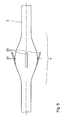
- an implantable medical electrode device in the form of a cardiac catheter indicated as a whole by 1, has an elongate, tube-like electrode body 2 which is located in front of the distal end 3 ( Figure 3) with a fixation zone 4 mm long is provided. Inside the electrode body 2 run in a separate inner tube 5, the coiled electrode leads 6, with which the pacing electrodes 7 shown for example in FIG. 3 are supplied with voltage.
- the wall 8 of the electrode body 2 is formed more flexibly than in the adjacent remaining areas.
- a stent-like, plastically deformable support structure 9 in the wall material embedded is a substantially tubular, plastically deformable, expandable expanded metal or plastic molded part.
- the expansion forces of this support structure 9 are by suitable choice of material and structuring of the webs 10 - vote by matching the web width, web height, the shape of the bending leg, etc. - on the elastic and geometric properties of the embedding material of the wall 8 of the fixing zone 4, which in turn the wall thickness and the choice of material, such as latex, silicone, polyurethane, is determined.
- a supply device 12 is provided around the electrode body 2, via the means of a syringe 13 via the connected feed line 14, a hydraulic pressure medium, such as physiological saline, in as pressure-tight Tube formed electrode body 2 with a pressure p H can be pressed.
- the proximal end 11 of the cardiac catheter 1 is formed by a connection plug 15 for the individual stimulation electrodes 7.
- the feeding device 12 is shown in FIG. 4.
- the connection 16 of the feed line 14 is located centrally in the wall of a cylindrical sleeve 17 surrounding the electrode body 2, between the end openings of which and the electrode body 2 each O-ring seals 18 are fitted. These are acted upon by sealing sleeves 47 which can be screwed onto the cylinder sleeve 17 so that the pressurized fluid can be pressed into the annular space between the electrode body 2 and the inner tube 5 via the connection 16 and a feed opening 19.
- the cardiac catheter 1 is advanced, for example, into the coronary sinus with its distal end 3 until the desired position of the stimulation electrodes 7 has been reached.
- the X-ray controllability of this process is by an appropriate design of the support structure 9 of a radiopaque material, such as suitable coated plastic, stainless steel, platinum, titanium alloys, magnesium or gold can be improved.
- the support structure 9 is widened plastically there and thus expands radially, as can be seen in Fig. 2. This is continued until the fixation zone 4 with its enlarged diameter rests against the vessel inner wall (not shown here) and thus fixes the cardiac catheter 1 in this position.
- the pressurized fluid is sucked off, whereby a negative pressure is created, which ensures that the fixing zone 4 contracts again, while the support structure 9 quasi collapses, which again the configuration shown in Fig. 1 is achieved and the Cardiac catheter 1 is freely movable.
- the expansion diameter D in the fixing zone 4 can be directly influenced by controlling the introduced volume of the pressure fluid or by the applied pressure, even in the case of a pneumatic control.
- the pressurized fluid can also be transmitted through an eccentric additional lumen in the electrode body 2 or through an outer, coaxially arranged tube, as is not shown in detail in the figures.
- an axial deformability can also be achieved by suitable shaping of the embedded support structure 9, so that the cardiac catheter 1 remains sufficiently flexible for placement in the vessels even in the region of the fixation zone 4.
- an additional definition of the cardiac catheter 1 can be achieved by suitable structuring of the outer surface of the fixation zone 4.
- web-shaped anchoring elements 20 are provided on the outside, distributed over the circumference, parallel to the longitudinal direction of the electrode body 2. In the unexpanded configuration, these anchoring elements are located 20 flat on the outside of the cardiac catheter 1, so that a smooth introduction is guaranteed.
- the anchoring elements 20 may be designed soft or stiff depending on the choice of material. Suitable materials are elastomers, other plastics or metals.
- the fixing zone 4 is provided with a designated as a whole with 21 drape configuration, which acts together with a coaxial with the electrode body applied tensile or shear loading as expansion means and will be explained in more detail below with reference to the individual figures.
- FIG. 6 shows a reduction in the wall thickness of the electrode body 2 in the region of the fixation zone 4.
- FIG. 8 an embodiment is shown in which three annular folds 22 lined up in the axial direction arise by three juxtaposed in the axial direction, narrow WandungsverPhynonne when pulling the Switzerlanddrahtung.
- the annular folds 22 also form a sawtooth profile after the expansion, as shown in Fig. 9.
- the holding force in the extension direction of the cardiac catheter 1 is greater than in the insertion direction.
- the wall 8 is designed so that when expanding with the help of (not shown) puller wire, the annular folds 22 slide over each other, so that several centrally located inner folds 23 and a plurality of peripherally located outer folds 24 arise.
- the increase in diameter of the electrode body 2 is based not only on a pure wrinkling, but also on a thickening of the material by forming a plurality, preferably at least three layers.
- Fig. 11 and 12 shows an embodiment in which a single annular fold 22 is formed, which pushes through introduced into the wall 8 thickenings 25 in layers over each other, that a locking of the layers takes place. If the inner fold 23 is pushed under the outer fold 24 when the fold is pushed together, the thickening 25 of the inner fold 23 snaps behind the corresponding thickening 25 of the outer fold 24, whereby the configuration formed is determined.
- FIG. 14 shows the corresponding region of the cardiac catheter 1 in the stretched state, in which the anchoring elements 20 conform to the elongate electrode body 2.
- the electrode body 2 in the fixing zone 4 is designed with regard to its choice of material and the wall diameter such that the flanks 26 of the forming annular folds 22 are stiffened. If the cardiac catheter 1, as shown in this figure, positioned in the vessel 27, the pull wire, not shown, is actuated and wrinkling occurs, as shown in Fig. 16 in an intermediate state. In this Condition, the vessel 27 is slightly overstretched. Upon further actuation of the puller wire, the annular folds 22 again fold over the radially maximally extended configuration, so that the stiffened flanks 26 lie one above the other and fix the cardiac catheter 1 in the vessel 27 (FIG. 17).
- a spreading device 28 is provided in the electrode body 2 in the region of the fixing zone 4, which supports the formation of wrinkles.
- This spreading device 28 has a cone 29 fixed in the electrode body 2, which cooperates with a spreading sleeve 31 mounted distally in front of it and acted upon by the puller wire 30.
- the cone 29 engages under the spreading arms 32 of the expansion sleeve 31, which thus radially expand and thus contribute to the formation of the annular fold 22.
- the wrinkling and the unfolding of the anchoring elements 20 is reversible.
- the wrinkling can be optimized both by varying the wall thicknesses of the electrode body 2 in the fixing zone 4 and by varying the degrees of hardness of the material or by preforming with memory effect.
- the distal end of the fixing zone 4 may be connected to a pull wire or pull cable which runs inside the electrode body 2 and is arranged to be movable relative thereto.
- the proximal end of the puller wire extends beyond the proximal end of the electrode body 2. Pulling on the puller wire or retaining the puller wire while simultaneously pushing the electrode body 2 forwardly allows the distal and proximal ends of the fixation zone 4 to move toward one another, which causes bulging of the annular fold 22, possibly forming the inner and outer fins Outside folds 23, 24 generated.
- a release of the resulting fixation of the cardiac catheter 1 can be achieved by pushing on the pull wire, if this is sufficiently stiff.
- a stylet may be inserted into the electrode body 2 with which the distal end of the flexible area is pushed forward again.
- the puller wire with the distal end can also serve as an abutment when the proximal part of the electrode body 2 is retracted. In any case, this will result in a contracting and smoothing of the wrinkles and a stretching of the fixation zone 4 with the release of the cardiac catheter 1.
- FIGS. 20 to 24 show a further variant for the expansion and contraction of the cardiac catheter 1 in the region of its fixation zone 4.
- the basis of this is the bistable tilting element 33 shown in plan view in FIG. 20, which consists of two limbs 34, 35 each bent in an S-shape. These are placed mirror-inverted and riveted together at the intersection points 36.
- an anchoring element 37 in the form of a sheet metal lamination is again attached, which is inwardly in the direction of the main axis connecting the crossing points 36.
- the two legs 34, 35 form - as Fig. 20 shows well - in plan view the shape of an eighth
- FIG. 21 shows two such tilting elements 33 in a configuration that corresponds to the expanded state in the application shown in FIGS. 23 and 24.
- the anchoring elements 37 carrying portions of the legs 34, 35 are convex, the remaining portions bent concave. This is a stable end position, which is umschnappbar by applying the concave portions of the legs 34, 35 outwardly into the second stable end position shown in Fig. 22.
- the anchoring elements 37 carrying portions of the legs 34, 35 are bent concavely, while the remaining portions are now convex.
- the tilting element 33 is thus umschnappbar between a concave-convex and convex-concave configuration for transfer between the expanded and the contracted state.
- the tilting element 33 with its legs 34, 35 is completely embedded in the wall 8 of the electrode body 2, so that the latter in turn forms an envelope closed to the outside. Only the anchoring elements 37 protrude out of the wall 8 to the outside.
- the embedded tilting elements 33 are brought into that bistable end position in which the anchoring elements 37 are retracted by concave shaping of the corresponding sections of the legs 34, 35.
- a deflated catheter balloon 39 is drawn as an expansion agent through the electrode body 2 to below this concave portion and inflated.
- the tilting elements 33 thereby jump into the other bistable end position shown in Fig. 24, in which the anchoring elements 37 by the convex shape of the overlapping portions of the legs 34, 35 after project outside and provide a reliable anchoring of the cardiac catheter 1 in a vessel, not shown.
Landscapes
- Health & Medical Sciences (AREA)
- Cardiology (AREA)
- Heart & Thoracic Surgery (AREA)
- Vascular Medicine (AREA)
- Engineering & Computer Science (AREA)
- Biomedical Technology (AREA)
- Nuclear Medicine, Radiotherapy & Molecular Imaging (AREA)
- Radiology & Medical Imaging (AREA)
- Life Sciences & Earth Sciences (AREA)
- Animal Behavior & Ethology (AREA)
- General Health & Medical Sciences (AREA)
- Public Health (AREA)
- Veterinary Medicine (AREA)
- Electrotherapy Devices (AREA)
- Media Introduction/Drainage Providing Device (AREA)
Applications Claiming Priority (1)
| Application Number | Priority Date | Filing Date | Title |
|---|---|---|---|
| DE102006011349A DE102006011349A1 (de) | 2006-03-11 | 2006-03-11 | Implantierbare medizinische Elektrodenvorrichtung, insbesondere kardiovaskuläre Herzschrittmacher- oder Defibrillator-Elektrodenvorrichtung |
Publications (3)
| Publication Number | Publication Date |
|---|---|
| EP1832309A2 true EP1832309A2 (fr) | 2007-09-12 |
| EP1832309A3 EP1832309A3 (fr) | 2007-10-24 |
| EP1832309B1 EP1832309B1 (fr) | 2009-06-03 |
Family
ID=38051987
Family Applications (1)
| Application Number | Title | Priority Date | Filing Date |
|---|---|---|---|
| EP07003085A Not-in-force EP1832309B1 (fr) | 2006-03-11 | 2007-02-14 | Dispositif médical implantable à électrodes, en particulier dispositif de défibrillation ou de stimulation cardiovasculaire à électrodes |
Country Status (4)
| Country | Link |
|---|---|
| US (1) | US7809447B2 (fr) |
| EP (1) | EP1832309B1 (fr) |
| AT (1) | ATE432733T1 (fr) |
| DE (2) | DE102006011349A1 (fr) |
Cited By (4)
| Publication number | Priority date | Publication date | Assignee | Title |
|---|---|---|---|---|
| WO2007143306A1 (fr) * | 2006-06-02 | 2007-12-13 | Cardiac Pacemakers, Inc. | Dérivation cardiaque possédant des structures raidisseuses pour la fixation |
| US8442656B2 (en) | 2006-06-02 | 2013-05-14 | Cardiac Pacemakers, Inc. | Cardiac lead having implantable stiffening structures for fixation |
| EP2777761A1 (fr) * | 2013-03-14 | 2014-09-17 | BIOTRONIK SE & Co. KG | Électrode implantable |
| EP2862594A1 (fr) * | 2013-10-17 | 2015-04-22 | BIOTRONIK SE & Co. KG | Fixation active et réversible d'électrodes CRT |
Families Citing this family (14)
| Publication number | Priority date | Publication date | Assignee | Title |
|---|---|---|---|---|
| US7983764B2 (en) * | 2005-08-12 | 2011-07-19 | Cardiac Pacemakers, Inc. | Co-radial lead with extendable/retractable fixation mechanism and apparatus therefor |
| US8825129B2 (en) * | 2010-03-05 | 2014-09-02 | Sri International | Indwelling nerve block catheters |
| CA2802753C (fr) | 2010-06-21 | 2018-07-31 | Zorion Medical, Inc. | Implants bioabsorbables |
| WO2012149511A2 (fr) | 2011-04-28 | 2012-11-01 | Synecor Llc | Systèmes de neuromodulation et procédés pour traiter des syndromes d'insuffisance cardiaque aiguë |
| US9855421B2 (en) | 2010-09-28 | 2018-01-02 | The Board Of Trustees Of The Leland Stanford Junior University | Device and method for positioning an electrode in tissue |
| US9872981B2 (en) | 2010-09-28 | 2018-01-23 | Biotrace Medical, Inc. | Device and method for positioning an electrode in a body cavity |
| US8986369B2 (en) | 2010-12-01 | 2015-03-24 | Zorion Medical, Inc. | Magnesium-based absorbable implants |
| US9446240B2 (en) | 2011-07-11 | 2016-09-20 | Interventional Autonomics Corporation | System and method for neuromodulation |
| US9067071B2 (en) | 2011-07-11 | 2015-06-30 | Interventional Autonomics Corporation | System and method for neuromodulation |
| US20130072995A1 (en) | 2011-07-11 | 2013-03-21 | Terrance Ransbury | Catheter system for acute neuromodulation |
| US8972027B2 (en) * | 2011-07-19 | 2015-03-03 | Shalom MANOVA | Implantable medical device including electrode element, anchoring element and elastic element |
| US9526887B2 (en) * | 2012-06-29 | 2016-12-27 | Nuvectra Corporation | Method of making a braided lead with imbedded fixation structures |
| CN106659880B (zh) | 2014-05-09 | 2019-06-18 | 比奥特雷斯医疗公司 | 用于在体腔中定位电极的装置和方法 |
| JP6632191B2 (ja) * | 2015-01-08 | 2020-01-22 | アドリアカイム株式会社 | 神経刺激電極 |
Citations (6)
| Publication number | Priority date | Publication date | Assignee | Title |
|---|---|---|---|---|
| US5170802A (en) | 1991-01-07 | 1992-12-15 | Medtronic, Inc. | Implantable electrode for location within a blood vessel |
| EP0546414A1 (fr) | 1991-12-12 | 1993-06-16 | Vitatron Medical B.V. | Conducteur de stimulateur cardiaque avec mécanisme de fixation amélioré |
| WO1994007564A2 (fr) | 1992-10-01 | 1994-04-14 | Cardiac Pacemakers, Inc. | Structure d'electrodes de defibrillation de type extenseur |
| US5411546A (en) | 1992-12-11 | 1995-05-02 | Siemens Elema Ab | Defibrillation electrode |
| WO1998042403A1 (fr) | 1997-03-25 | 1998-10-01 | Intermedics Inc. | Fil d'electrode permettant la stimulation ou la defibrillation du coeur via le sinus coronaire |
| US20060036307A1 (en) | 2004-08-16 | 2006-02-16 | Cardiac Pacemakers, Inc. | Lead assembly and methods including a push tube |
Family Cites Families (10)
| Publication number | Priority date | Publication date | Assignee | Title |
|---|---|---|---|---|
| DE2249690B2 (de) * | 1972-10-11 | 1976-11-25 | Kernforschungsanlage Jülich GmbH, 517OJuIiCh | Sicherheitseinrichtung fuer unter druck stehende anlagen |
| DE2305262A1 (de) * | 1973-02-02 | 1974-08-08 | Siemens Ag | Endocardelektrode |
| EP0261582B1 (fr) * | 1986-09-23 | 1992-12-16 | Siemens-Elema AB | Electrode de stimulateur cardiaque |
| DE3718139C1 (de) * | 1987-05-29 | 1988-12-08 | Strahlen Umweltforsch Gmbh | Herzkatheter |
| US4913164A (en) * | 1988-09-27 | 1990-04-03 | Intermedics, Inc. | Extensible passive fixation mechanism for lead assembly of an implantable cardiac stimulator |
| FR2742058B1 (fr) * | 1995-12-12 | 1998-03-06 | Ela Medical Sa | Sondes a barbes d'ancrage pliables pour dispositif medical implante, notamment pour stimulateur cardiaque |
| US5871483A (en) * | 1996-01-19 | 1999-02-16 | Ep Technologies, Inc. | Folding electrode structures |
| SE9802104D0 (sv) * | 1998-06-12 | 1998-06-12 | Pacesetter Ab | Medical electrode device |
| DE19930237A1 (de) * | 1999-06-25 | 2000-12-28 | Biotronik Mess & Therapieg | Elektrodenanordnung |
| US6805707B1 (en) * | 2001-12-27 | 2004-10-19 | Advanced Cardiovascular Systems, Inc. | Stent with improved ring and link pattern |
-
2006
- 2006-03-11 DE DE102006011349A patent/DE102006011349A1/de not_active Withdrawn
-
2007
- 2007-02-14 DE DE502007000797T patent/DE502007000797D1/de active Active
- 2007-02-14 EP EP07003085A patent/EP1832309B1/fr not_active Not-in-force
- 2007-02-14 AT AT07003085T patent/ATE432733T1/de active
- 2007-03-08 US US11/683,900 patent/US7809447B2/en not_active Expired - Fee Related
Patent Citations (6)
| Publication number | Priority date | Publication date | Assignee | Title |
|---|---|---|---|---|
| US5170802A (en) | 1991-01-07 | 1992-12-15 | Medtronic, Inc. | Implantable electrode for location within a blood vessel |
| EP0546414A1 (fr) | 1991-12-12 | 1993-06-16 | Vitatron Medical B.V. | Conducteur de stimulateur cardiaque avec mécanisme de fixation amélioré |
| WO1994007564A2 (fr) | 1992-10-01 | 1994-04-14 | Cardiac Pacemakers, Inc. | Structure d'electrodes de defibrillation de type extenseur |
| US5411546A (en) | 1992-12-11 | 1995-05-02 | Siemens Elema Ab | Defibrillation electrode |
| WO1998042403A1 (fr) | 1997-03-25 | 1998-10-01 | Intermedics Inc. | Fil d'electrode permettant la stimulation ou la defibrillation du coeur via le sinus coronaire |
| US20060036307A1 (en) | 2004-08-16 | 2006-02-16 | Cardiac Pacemakers, Inc. | Lead assembly and methods including a push tube |
Cited By (4)
| Publication number | Priority date | Publication date | Assignee | Title |
|---|---|---|---|---|
| WO2007143306A1 (fr) * | 2006-06-02 | 2007-12-13 | Cardiac Pacemakers, Inc. | Dérivation cardiaque possédant des structures raidisseuses pour la fixation |
| US8442656B2 (en) | 2006-06-02 | 2013-05-14 | Cardiac Pacemakers, Inc. | Cardiac lead having implantable stiffening structures for fixation |
| EP2777761A1 (fr) * | 2013-03-14 | 2014-09-17 | BIOTRONIK SE & Co. KG | Électrode implantable |
| EP2862594A1 (fr) * | 2013-10-17 | 2015-04-22 | BIOTRONIK SE & Co. KG | Fixation active et réversible d'électrodes CRT |
Also Published As
| Publication number | Publication date |
|---|---|
| DE502007000797D1 (de) | 2009-07-16 |
| ATE432733T1 (de) | 2009-06-15 |
| US20070213798A1 (en) | 2007-09-13 |
| US7809447B2 (en) | 2010-10-05 |
| EP1832309A3 (fr) | 2007-10-24 |
| DE102006011349A1 (de) | 2007-09-13 |
| EP1832309B1 (fr) | 2009-06-03 |
Similar Documents
| Publication | Publication Date | Title |
|---|---|---|
| EP1832309A2 (fr) | Dispositif médical implantable à électrodes, en particulier dispositif de défibrillation ou de stimulation cardiovasculaire à électrodes | |
| DE69125476T2 (de) | Katheter mit foramenartiger verankerung | |
| DE69113818T2 (de) | In den körper implantierbare herzklappenprothese sowie katheter für die implantation einer solchen herzklappenprothese. | |
| DE69434819T2 (de) | Einsetzen einer prothese | |
| DE69635402T2 (de) | Führungseinheit mit internem Führungsdraht aus einer Formgedächtnislegierung | |
| DE69123982T2 (de) | Dehnung aufrechterhaltendes führungselement sowie dilatator | |
| DE60309843T2 (de) | Vorrichtung zur verankerung von endoluminalprothesen | |
| EP1200018B1 (fr) | Catheter d'insertion pour protheses vasculaires | |
| DE69633265T2 (de) | Führungsdrahteinheit | |
| DE69935075T2 (de) | Biegsames transmyokardimplantat zur induktion der angiogenese | |
| DE3250058C2 (fr) | ||
| DE60115239T2 (de) | Vorrichtung zum einbringen eines stents | |
| DE69101385T2 (de) | Selbstausdehnbare prothese mit stabiler axialer länge. | |
| DE69634791T2 (de) | Stent mit mehrfacher Verankerung | |
| DE602004010344T2 (de) | Katheter ohne Ballon zum Einsetzen eines Stents | |
| DE10334868A1 (de) | Implantierbare Einrichtung als Organklappenersatz | |
| DE2119172B2 (de) | Ballon-katheter und verfahren zu seiner herstellung | |
| WO2014026870A2 (fr) | Dispositif implantable destiné à être utilisé dans un corps humain et/ou animal pour remplacer un clapet organique | |
| DE3342798T1 (de) | Prothese mit einem dehnbaren oder zusammenziehbaren rohrförmigen Körper | |
| DE102015111205A1 (de) | Behandlungsvorrichtung einer Blutbahn | |
| WO2009077845A2 (fr) | Implant de soutien, notamment endoprothèse vasculaire, et cathéter de greffage pour implant de soutien | |
| WO2016062665A2 (fr) | Stent destiné à servir de tuteur à une veine et système pour poser un stent | |
| WO2013068127A1 (fr) | Dispositif pour implanter des éléments d'endoprothèse dans ou autour d'un organe creux | |
| EP2775968A1 (fr) | Dispositif pour implanter des éléments d'endoprothèse dans ou autour d'un organe creux | |
| EP3400914A1 (fr) | Poignée pour un cathéter et cathéter correspondant |
Legal Events
| Date | Code | Title | Description |
|---|---|---|---|
| PUAI | Public reference made under article 153(3) epc to a published international application that has entered the european phase |
Free format text: ORIGINAL CODE: 0009012 |
|
| AK | Designated contracting states |
Kind code of ref document: A2 Designated state(s): AT BE BG CH CY CZ DE DK EE ES FI FR GB GR HU IE IS IT LI LT LU LV MC NL PL PT RO SE SI SK TR |
|
| AX | Request for extension of the european patent |
Extension state: AL BA HR MK YU |
|
| PUAL | Search report despatched |
Free format text: ORIGINAL CODE: 0009013 |
|
| AK | Designated contracting states |
Kind code of ref document: A3 Designated state(s): AT BE BG CH CY CZ DE DK EE ES FI FR GB GR HU IE IS IT LI LT LU LV MC NL PL PT RO SE SI SK TR |
|
| AX | Request for extension of the european patent |
Extension state: AL BA HR MK YU |
|
| 17P | Request for examination filed |
Effective date: 20080329 |
|
| 17Q | First examination report despatched |
Effective date: 20080508 |
|
| AKX | Designation fees paid |
Designated state(s): AT BE BG CH CY CZ DE DK EE ES FI FR GB GR HU IE IS IT LI LT LU LV MC NL PL PT RO SE SI SK TR |
|
| GRAP | Despatch of communication of intention to grant a patent |
Free format text: ORIGINAL CODE: EPIDOSNIGR1 |
|
| GRAS | Grant fee paid |
Free format text: ORIGINAL CODE: EPIDOSNIGR3 |
|
| GRAA | (expected) grant |
Free format text: ORIGINAL CODE: 0009210 |
|
| AK | Designated contracting states |
Kind code of ref document: B1 Designated state(s): AT BE BG CH CY CZ DE DK EE ES FI FR GB GR HU IE IS IT LI LT LU LV MC NL PL PT RO SE SI SK TR |
|
| REG | Reference to a national code |
Ref country code: GB Ref legal event code: FG4D Free format text: NOT ENGLISH |
|
| REG | Reference to a national code |
Ref country code: CH Ref legal event code: EP |
|
| REG | Reference to a national code |
Ref country code: IE Ref legal event code: FG4D Free format text: LANGUAGE OF EP DOCUMENT: GERMAN |
|
| REF | Corresponds to: |
Ref document number: 502007000797 Country of ref document: DE Date of ref document: 20090716 Kind code of ref document: P |
|
| REG | Reference to a national code |
Ref country code: SE Ref legal event code: TRGR |
|
| PG25 | Lapsed in a contracting state [announced via postgrant information from national office to epo] |
Ref country code: FI Free format text: LAPSE BECAUSE OF FAILURE TO SUBMIT A TRANSLATION OF THE DESCRIPTION OR TO PAY THE FEE WITHIN THE PRESCRIBED TIME-LIMIT Effective date: 20090603 Ref country code: LT Free format text: LAPSE BECAUSE OF FAILURE TO SUBMIT A TRANSLATION OF THE DESCRIPTION OR TO PAY THE FEE WITHIN THE PRESCRIBED TIME-LIMIT Effective date: 20090603 |
|
| NLV1 | Nl: lapsed or annulled due to failure to fulfill the requirements of art. 29p and 29m of the patents act | ||
| PG25 | Lapsed in a contracting state [announced via postgrant information from national office to epo] |
Ref country code: PL Free format text: LAPSE BECAUSE OF FAILURE TO SUBMIT A TRANSLATION OF THE DESCRIPTION OR TO PAY THE FEE WITHIN THE PRESCRIBED TIME-LIMIT Effective date: 20090603 Ref country code: NL Free format text: LAPSE BECAUSE OF FAILURE TO SUBMIT A TRANSLATION OF THE DESCRIPTION OR TO PAY THE FEE WITHIN THE PRESCRIBED TIME-LIMIT Effective date: 20090603 Ref country code: SI Free format text: LAPSE BECAUSE OF FAILURE TO SUBMIT A TRANSLATION OF THE DESCRIPTION OR TO PAY THE FEE WITHIN THE PRESCRIBED TIME-LIMIT Effective date: 20090603 Ref country code: LV Free format text: LAPSE BECAUSE OF FAILURE TO SUBMIT A TRANSLATION OF THE DESCRIPTION OR TO PAY THE FEE WITHIN THE PRESCRIBED TIME-LIMIT Effective date: 20090603 |
|
| PG25 | Lapsed in a contracting state [announced via postgrant information from national office to epo] |
Ref country code: IS Free format text: LAPSE BECAUSE OF FAILURE TO SUBMIT A TRANSLATION OF THE DESCRIPTION OR TO PAY THE FEE WITHIN THE PRESCRIBED TIME-LIMIT Effective date: 20091003 Ref country code: CZ Free format text: LAPSE BECAUSE OF FAILURE TO SUBMIT A TRANSLATION OF THE DESCRIPTION OR TO PAY THE FEE WITHIN THE PRESCRIBED TIME-LIMIT Effective date: 20090603 Ref country code: RO Free format text: LAPSE BECAUSE OF FAILURE TO SUBMIT A TRANSLATION OF THE DESCRIPTION OR TO PAY THE FEE WITHIN THE PRESCRIBED TIME-LIMIT Effective date: 20090603 Ref country code: EE Free format text: LAPSE BECAUSE OF FAILURE TO SUBMIT A TRANSLATION OF THE DESCRIPTION OR TO PAY THE FEE WITHIN THE PRESCRIBED TIME-LIMIT Effective date: 20090603 Ref country code: ES Free format text: LAPSE BECAUSE OF FAILURE TO SUBMIT A TRANSLATION OF THE DESCRIPTION OR TO PAY THE FEE WITHIN THE PRESCRIBED TIME-LIMIT Effective date: 20090914 |
|
| PG25 | Lapsed in a contracting state [announced via postgrant information from national office to epo] |
Ref country code: SK Free format text: LAPSE BECAUSE OF FAILURE TO SUBMIT A TRANSLATION OF THE DESCRIPTION OR TO PAY THE FEE WITHIN THE PRESCRIBED TIME-LIMIT Effective date: 20090603 |
|
| PG25 | Lapsed in a contracting state [announced via postgrant information from national office to epo] |
Ref country code: BG Free format text: LAPSE BECAUSE OF FAILURE TO SUBMIT A TRANSLATION OF THE DESCRIPTION OR TO PAY THE FEE WITHIN THE PRESCRIBED TIME-LIMIT Effective date: 20090903 Ref country code: PT Free format text: LAPSE BECAUSE OF FAILURE TO SUBMIT A TRANSLATION OF THE DESCRIPTION OR TO PAY THE FEE WITHIN THE PRESCRIBED TIME-LIMIT Effective date: 20091003 |
|
| PLBE | No opposition filed within time limit |
Free format text: ORIGINAL CODE: 0009261 |
|
| STAA | Information on the status of an ep patent application or granted ep patent |
Free format text: STATUS: NO OPPOSITION FILED WITHIN TIME LIMIT |
|
| PG25 | Lapsed in a contracting state [announced via postgrant information from national office to epo] |
Ref country code: DK Free format text: LAPSE BECAUSE OF FAILURE TO SUBMIT A TRANSLATION OF THE DESCRIPTION OR TO PAY THE FEE WITHIN THE PRESCRIBED TIME-LIMIT Effective date: 20090603 |
|
| 26N | No opposition filed |
Effective date: 20100304 |
|
| BERE | Be: lapsed |
Owner name: BIOTRONIK CRM PATENT A.G. Effective date: 20100228 |
|
| PG25 | Lapsed in a contracting state [announced via postgrant information from national office to epo] |
Ref country code: MC Free format text: LAPSE BECAUSE OF NON-PAYMENT OF DUE FEES Effective date: 20100301 Ref country code: GR Free format text: LAPSE BECAUSE OF FAILURE TO SUBMIT A TRANSLATION OF THE DESCRIPTION OR TO PAY THE FEE WITHIN THE PRESCRIBED TIME-LIMIT Effective date: 20090904 |
|
| PG25 | Lapsed in a contracting state [announced via postgrant information from national office to epo] |
Ref country code: BE Free format text: LAPSE BECAUSE OF NON-PAYMENT OF DUE FEES Effective date: 20100228 |
|
| PG25 | Lapsed in a contracting state [announced via postgrant information from national office to epo] |
Ref country code: IT Free format text: LAPSE BECAUSE OF FAILURE TO SUBMIT A TRANSLATION OF THE DESCRIPTION OR TO PAY THE FEE WITHIN THE PRESCRIBED TIME-LIMIT Effective date: 20090603 |
|
| PG25 | Lapsed in a contracting state [announced via postgrant information from national office to epo] |
Ref country code: CY Free format text: LAPSE BECAUSE OF FAILURE TO SUBMIT A TRANSLATION OF THE DESCRIPTION OR TO PAY THE FEE WITHIN THE PRESCRIBED TIME-LIMIT Effective date: 20090603 |
|
| PG25 | Lapsed in a contracting state [announced via postgrant information from national office to epo] |
Ref country code: HU Free format text: LAPSE BECAUSE OF FAILURE TO SUBMIT A TRANSLATION OF THE DESCRIPTION OR TO PAY THE FEE WITHIN THE PRESCRIBED TIME-LIMIT Effective date: 20091204 Ref country code: LU Free format text: LAPSE BECAUSE OF NON-PAYMENT OF DUE FEES Effective date: 20100214 |
|
| PG25 | Lapsed in a contracting state [announced via postgrant information from national office to epo] |
Ref country code: TR Free format text: LAPSE BECAUSE OF FAILURE TO SUBMIT A TRANSLATION OF THE DESCRIPTION OR TO PAY THE FEE WITHIN THE PRESCRIBED TIME-LIMIT Effective date: 20090603 |
|
| REG | Reference to a national code |
Ref country code: AT Ref legal event code: MM01 Ref document number: 432733 Country of ref document: AT Kind code of ref document: T Effective date: 20120214 |
|
| PGFP | Annual fee paid to national office [announced via postgrant information from national office to epo] |
Ref country code: GB Payment date: 20130219 Year of fee payment: 7 Ref country code: SE Payment date: 20130219 Year of fee payment: 7 |
|
| PG25 | Lapsed in a contracting state [announced via postgrant information from national office to epo] |
Ref country code: AT Free format text: LAPSE BECAUSE OF NON-PAYMENT OF DUE FEES Effective date: 20120214 |
|
| REG | Reference to a national code |
Ref country code: SE Ref legal event code: EUG |
|
| GBPC | Gb: european patent ceased through non-payment of renewal fee |
Effective date: 20140214 |
|
| PG25 | Lapsed in a contracting state [announced via postgrant information from national office to epo] |
Ref country code: SE Free format text: LAPSE BECAUSE OF NON-PAYMENT OF DUE FEES Effective date: 20140215 |
|
| PG25 | Lapsed in a contracting state [announced via postgrant information from national office to epo] |
Ref country code: GB Free format text: LAPSE BECAUSE OF NON-PAYMENT OF DUE FEES Effective date: 20140214 |
|
| REG | Reference to a national code |
Ref country code: DE Ref legal event code: R082 Ref document number: 502007000797 Country of ref document: DE Representative=s name: RANDOLL, SOEREN, DIPL.-CHEM. UNIV. DR. RER. NA, DE |
|
| REG | Reference to a national code |
Ref country code: FR Ref legal event code: PLFP Year of fee payment: 10 |
|
| PGFP | Annual fee paid to national office [announced via postgrant information from national office to epo] |
Ref country code: FR Payment date: 20160222 Year of fee payment: 10 |
|
| PGFP | Annual fee paid to national office [announced via postgrant information from national office to epo] |
Ref country code: CH Payment date: 20170221 Year of fee payment: 11 Ref country code: DE Payment date: 20170223 Year of fee payment: 11 |
|
| PGFP | Annual fee paid to national office [announced via postgrant information from national office to epo] |
Ref country code: IE Payment date: 20170223 Year of fee payment: 11 |
|
| REG | Reference to a national code |
Ref country code: FR Ref legal event code: ST Effective date: 20171031 |
|
| PG25 | Lapsed in a contracting state [announced via postgrant information from national office to epo] |
Ref country code: FR Free format text: LAPSE BECAUSE OF NON-PAYMENT OF DUE FEES Effective date: 20170228 |
|
| REG | Reference to a national code |
Ref country code: DE Ref legal event code: R082 Ref document number: 502007000797 Country of ref document: DE Ref country code: DE Ref legal event code: R081 Ref document number: 502007000797 Country of ref document: DE Owner name: BIOTRONIK SE & CO. KG, DE Free format text: FORMER OWNER: BIOTRONIK CRM PATENT AG, BAAR, CH |
|
| REG | Reference to a national code |
Ref country code: DE Ref legal event code: R119 Ref document number: 502007000797 Country of ref document: DE |
|
| REG | Reference to a national code |
Ref country code: CH Ref legal event code: PL |
|
| REG | Reference to a national code |
Ref country code: IE Ref legal event code: MM4A |
|
| PG25 | Lapsed in a contracting state [announced via postgrant information from national office to epo] |
Ref country code: CH Free format text: LAPSE BECAUSE OF NON-PAYMENT OF DUE FEES Effective date: 20180228 Ref country code: LI Free format text: LAPSE BECAUSE OF NON-PAYMENT OF DUE FEES Effective date: 20180228 |
|
| PG25 | Lapsed in a contracting state [announced via postgrant information from national office to epo] |
Ref country code: IE Free format text: LAPSE BECAUSE OF NON-PAYMENT OF DUE FEES Effective date: 20180214 Ref country code: DE Free format text: LAPSE BECAUSE OF NON-PAYMENT OF DUE FEES Effective date: 20180901 |