EP1832327A2 - Filtre et procédé de lavage à contre courant du filtre - Google Patents
Filtre et procédé de lavage à contre courant du filtre Download PDFInfo
- Publication number
- EP1832327A2 EP1832327A2 EP07102632A EP07102632A EP1832327A2 EP 1832327 A2 EP1832327 A2 EP 1832327A2 EP 07102632 A EP07102632 A EP 07102632A EP 07102632 A EP07102632 A EP 07102632A EP 1832327 A2 EP1832327 A2 EP 1832327A2
- Authority
- EP
- European Patent Office
- Prior art keywords
- porous body
- liquid
- backwashing
- slits
- backwashing liquid
- Prior art date
- Legal status (The legal status is an assumption and is not a legal conclusion. Google has not performed a legal analysis and makes no representation as to the accuracy of the status listed.)
- Withdrawn
Links
Images


Classifications
-
- B—PERFORMING OPERATIONS; TRANSPORTING
- B01—PHYSICAL OR CHEMICAL PROCESSES OR APPARATUS IN GENERAL
- B01D—SEPARATION
- B01D39/00—Filtering material for liquid or gaseous fluids
- B01D39/14—Other self-supporting filtering material ; Other filtering material
- B01D39/20—Other self-supporting filtering material ; Other filtering material of inorganic material, e.g. asbestos paper, metallic filtering material of non-woven wires
- B01D39/2068—Other inorganic materials, e.g. ceramics
-
- B—PERFORMING OPERATIONS; TRANSPORTING
- B01—PHYSICAL OR CHEMICAL PROCESSES OR APPARATUS IN GENERAL
- B01D—SEPARATION
- B01D35/00—Filtering devices having features not specifically covered by groups B01D24/00 - B01D33/00, or for applications not specifically covered by groups B01D24/00 - B01D33/00; Auxiliary devices for filtration; Filter housing constructions
-
- B—PERFORMING OPERATIONS; TRANSPORTING
- B01—PHYSICAL OR CHEMICAL PROCESSES OR APPARATUS IN GENERAL
- B01D—SEPARATION
- B01D29/00—Filters with filtering elements stationary during filtration, e.g. pressure or suction filters, not covered by groups B01D24/00 - B01D27/00; Filtering elements therefor
- B01D29/50—Filters with filtering elements stationary during filtration, e.g. pressure or suction filters, not covered by groups B01D24/00 - B01D27/00; Filtering elements therefor with multiple filtering elements, characterised by their mutual disposition
- B01D29/52—Filters with filtering elements stationary during filtration, e.g. pressure or suction filters, not covered by groups B01D24/00 - B01D27/00; Filtering elements therefor with multiple filtering elements, characterised by their mutual disposition in parallel connection
-
- B—PERFORMING OPERATIONS; TRANSPORTING
- B01—PHYSICAL OR CHEMICAL PROCESSES OR APPARATUS IN GENERAL
- B01D—SEPARATION
- B01D29/00—Filters with filtering elements stationary during filtration, e.g. pressure or suction filters, not covered by groups B01D24/00 - B01D27/00; Filtering elements therefor
- B01D29/62—Regenerating the filter material in the filter
- B01D29/66—Regenerating the filter material in the filter by flushing, e.g. counter-current air-bumps
-
- B—PERFORMING OPERATIONS; TRANSPORTING
- B01—PHYSICAL OR CHEMICAL PROCESSES OR APPARATUS IN GENERAL
- B01D—SEPARATION
- B01D63/00—Apparatus in general for separation processes using semi-permeable membranes
- B01D63/06—Tubular membrane modules
- B01D63/066—Tubular membrane modules with a porous block having membrane coated passages
-
- B—PERFORMING OPERATIONS; TRANSPORTING
- B01—PHYSICAL OR CHEMICAL PROCESSES OR APPARATUS IN GENERAL
- B01D—SEPARATION
- B01D65/00—Accessories or auxiliary operations, in general, for separation processes or apparatus using semi-permeable membranes
- B01D65/02—Membrane cleaning or sterilisation ; Membrane regeneration
-
- B—PERFORMING OPERATIONS; TRANSPORTING
- B01—PHYSICAL OR CHEMICAL PROCESSES OR APPARATUS IN GENERAL
- B01D—SEPARATION
- B01D2201/00—Details relating to filtering apparatus
- B01D2201/62—Honeycomb-like
-
- B—PERFORMING OPERATIONS; TRANSPORTING
- B01—PHYSICAL OR CHEMICAL PROCESSES OR APPARATUS IN GENERAL
- B01D—SEPARATION
- B01D2313/00—Details relating to membrane modules or apparatus
- B01D2313/10—Specific supply elements
-
- B—PERFORMING OPERATIONS; TRANSPORTING
- B01—PHYSICAL OR CHEMICAL PROCESSES OR APPARATUS IN GENERAL
- B01D—SEPARATION
- B01D2321/00—Details relating to membrane cleaning, regeneration, sterilization or to the prevention of fouling
- B01D2321/04—Backflushing
Definitions
- the present invention relates to a filter and a method for backwashing the filter, and, more particularly, to a filter which can be uniformly and totally backwashed and a method for backwashing the filter.
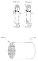
- a monolithic filter used as a filter for solid-liquid separation as in water purification process is a columnar porous body (monolithic filter) 31 in which a plurality of flow paths 32 are formed in parallel in axial direction as shown in Fig. 5.
- a liquid to be treated raw liquid
- the liquid to be treated permeates through the pore of the porous body and flows out of the porous body.
- suspended materials or harmful materials such as pathogenic microorganisms are removed at walls of the porous body and the liquid flowing out of the porous body can be recovered as a purified filtrate.
- Patent Document 1 JP-B-6-16819
- the present invention has been accomplished to solve the above problems and provides a filter which can be totally and uniformly washed by backwashing and a method for backwashing of the filter.
- a filter according to [1] further provided with a casing capable of containing the porous body therein, said casing having a raw liquid feed opening capable of feeding a liquid to be treated (raw liquid) to the porous body and a filtrate discharging opening capable of discharging to the outside the filtrate flowing out of the porous body, said casing further having a backwashing liquid feed opening capable of feeding a backwashing liquid to the porous body and being formed to be served as bifunctionally or independently of the filtrate discharging opening and a backwashing liquid discharging opening capable of discharging to the outside the backwashing liquid flowing out of the porous body and being formed to be served as bifunctionallyor independently of the raw liquid feed opening, a flow stop being disposed at the position on the side of the backwashing liquid discharging opening with respect to the backwashing inflow slits in the space between the casing and the porous body so that the backwashing liquid introduced from the backwashing liquid feed opening does not move to the side of the backwash
- [4] A method for backwashing the filter according to any one of [1]-[3], which comprises allowing a backwashing liquid to flow into the filter from at least the backwashing liquid inflow slits and discharging the backwashing liquid from an end of the porous body.
- the backwashing liquid inflow slits formed in the porous body are disposed in such a manner that 75% or more of their length in axial direction is positioned on the end side of the porous body from which the backwashing liquid does not flow out with respect to the position which is 60% of the length of the porous body in axial direction from the end of the porous body from which the backwashing liquid flows out, most of the backwashing liquid flows into the porous body from the backwashing liquid inflow slits at the time of backwashing, whereby it becomes possible to uniformly backwash the whole of the porous body.
- the filter 100 of this embodiment has a columnar porous body 1 in which a plurality of flow paths 2 are formed in parallel in axial direction, a plurality of liquid collecting slits 3 extending in axial direction and communicating, a group of the flow paths 2 formed in parallel, with the outside of the porous body 1 is formed, and both ends of the group of the flow paths 2a communicating with the liquid collecting slits 3 are plugged (both end-plugged flowpaths).
- a liquid to be treated which is fed to the flow paths 2 from one end 4 side of the porous body 1 permeates through the pores of the porous body 1 and flows out of the porous body 1, and during backwashing, a backwashing liquid flowing into the porous body 1 from at least a part of the liquid collecting slits 3 permeates through the pores of the porous body 1 and flows out from the one end 4 side of the porous body 1 (backwashing liquid discharging end 17).
- liquid collecting slits 3a into which the backwashing liquid can flow (backwashing liquid inflow slits) among the liquid collecting slits 3 are disposed in such a manner that 75% or more of the length in axial direction is positioned on the other end 5 (backwashing liquid non-outflow end 18) side of the porous body 1 with respect to the position 6 which is 60% of the length of the porous body 1 in axial direction from the backwashing liquid outflow end 17 of the porous body 1.
- 100% of the liquid collecting slits 3 (backwashing liquid inflow slits 3a) are positioned on the side of the backwashing liquid non-outflow end 18 with respect to the position 6 of 60%.
- Fig. 1 is a perspective view schematically showing one embodiment of a filter of the present invention. In Fig. 1, the filter is illustrated so that the contained porous body is visible through casing.
- the backwashing liquid inflow slits formed in the porous body are disposed in such a manner that 75% or more of their length in axial direction is positioned on the side of the backwashing liquid non-outflow end with respect to the position which is 60% of the length of the porous body in axial direction from one end of the porous body, most of the backwashing liquid flows into the porous body from the backwashing liquid inflow slits at the time of backwashing, whereby it becomes possible to uniformly backwash the whole of the porous body in lengthwise direction from the backwashing liquid inflow slits to the backwashing liquid non-inflow end.
- the amount of backwashing liquid on the side of the backwashing liquid non-outflow end with respect to the backwashing liquid inflow slits is small, and suspended materials or the like accumulated on the side of the backwashing liquid non-outflow end of the porous body cannot be sufficiently peeled off, and the whole porous body cannot be uniformly washed.
- the filter of the present invention it is preferred that 75% ormore of the length in axial direction of the backwashing liquid inflow slits is positioned on the side of the backwashing liquid non-outflow end with respect to the position which is 60% of the length of the porous body in axial direction from the side of the backwashing liquid outflow end of the porous body, and it is preferred that the backwashing liquid inflow slits are positioned as close as possible to the backwashing liquid non-outflow end.
- the length in axial direction and area of the backwashing liquid inflow slits are not particularly limited, and can be suitably determined in such a range that pressure loss at filtering and backwashing is not too large and that mechanical strength of the porous body does not lower.
- the length in axial direction of the backwashing liquid inflow slits is preferably, for example, about 50% of the length of the slits in depth direction (direction of being incised in the porous body in perpendicular to the axial direction).
- the filter 100 of the present invention is further provided with a casing 11 capable of containing the porous body 1 therein.
- the casing 11 has a raw liquid feed opening 12 for feeding a liquid to be treated (raw liquid) to the porous body 1 and a filtrate discharging opening 13 which can discharge the filtrate flowing out of the porous body 1 to the outside.
- the casing 11 further has a backwashing liquid feed opening 19 which can feed a backwashing liquid to the porous body 1 and a backwashing liquid discharging opening 20 which can discharge the backwashing liquid flowing out of the porous body 1 to the outside.
- the backwashing liquid feed opening 19 serves also as the filtrate discharging opening 13 and the backwashing liquid discharging opening 20 serves also as the raw liquid feed opening 12, and the combination is not limited thereto. That is, the backwashing liquid feed opening 19 may be served as the filtrate discharging opening 13 or may be formed independently of the raw liquid feed opening 12. Furthermore, the backwashing liquid discharging opening 20 may be to be served also as the raw liquid feed opening 12 or may be formed independently of the raw liquid feed opening 12.
- a seal ring 14 is fitted at each of one end 4 and the other end 5 of the porous body 1, and the gap between the porous body 1 and the casing is sealed by the seal ring 14.
- the filter 100 of the present invention in carrying out the filtration treatment, a raw liquid is fed to flow paths 2 through the raw liquid feed opening 12 from the one end 4 side of the porous body 1, and the filtrate filtered through the pores of the porous body 1 is discharged to the outside of the porous body 1 from the side face part 7 and liquid collecting slits 3 of the porous body 1.
- the discharged filtrate enters into the space 15 surrounded with the side face part 7 of the porous body 1, the casing 11 and the seal rings 14 and is discharged to the outside of the filter 100 from the filtrate discharging opening 13.
- a backwashing liquid is allowed to flow into the filter 100 from the backwashing liquid feed opening 19, and most of the backwashing liquid is introduced from liquid collecting slits 3 (backwashing liquid inflow slits 3a), is allowed to flow into the flow paths 2a both ends of which are plugged, enters into the flow paths 2 through pores of the porous body 1, and is discharged to the outside of the filter 100 from the one end 4 (backwashing liquid outflow end 17) side of the porous body 1 through the backwashing liquid discharging opening 20.
- Fig. 2 is a perspective view showing another embodiment of the filter of the present invention.
- the filter is also illustrated so that the porous body 1 is visible through the casing 11 as in Fig. 1.
- a flow stop 16 is disposed at the position on the side of backwashing liquid discharging opening 20 with respect to the backwashing inflow slits 3a in the void (space 15) between the casing 11 and the porous body 1 so that the backwashing liquid introduced from the backwashing liquid feed opening 19 does not move to the backwashing liquid discharging opening 20 side through the void (space 15) between the casing 11 and the porous body 1.
- liquid collecting slits 3 may further be formed at the position on the side of the backwashing liquid discharging opening 20 with respect to the position at which the flow stop 16 is provided.
- the backwashing liquid is prevented from moving to the side of the backwashing liquid discharging opening 20 by the flow stop 16, and hence the backwashing liquid does not flow into the porous body from the backwashing liquid non-inflow slits 3b disposed at the position on the side of the backwashing liquid discharging opening 20.
- the backwashing liquid non-inflow slits 3b are not included in the backwashing liquid inflow slits 3a.
- the backwashing liquid flows into the porous body also from the backwashing liquid non-inflow slits 3b, and, hence, "length of backwashing liquid inflow slit in axial direction" means the total of the length of the backwashing liquid inflow slit 3a in axial direction and the length of the backwashing liquid non-inflow slit 3b in axial direction in Fig. 2.
- the raw liquid feed opening in each filter is connected through a flange to a raw liquid feed header tube for feeding the raw liquid to each filter, and the filtrate discharging opening is connected through a flange to a filtrate recovery header tube for recovering all the filtrates in total.
- a filter of the present invention has a porous body which is monolithic.
- the porous body is preferably a ceramic porous body.
- the ceramics constituting the porous body include alumina (Al 2 O 3 ), titania (TiO 2 ), mullite (Al 2 O 3 ⁇ SiO 2 ), and zirconia (ZrO 2 ).
- alumina is suitable because raw materials having controlled particle diameter are easily available, stable slurry can be prepared, and alumina has high corrosion resistance.
- Ceramics has such various merits that it is high in reliability because of its excellent mechanical strength and durability and less in deterioration caused by chemical cleaning with acid or alkali because of its high corrosion resistance, and furthermore accurate control of average pore diameter which determines filtering ability is possible.
- the shape of section perpendicular to the axial direction is not particularly limited, and it may be circle, ellipse, oval, triangle, quadrilateral and the like, and a columnar (cylindrical) body having a circular section is particularly preferred because the columnar body is easy in extrusion molding, less in firing deformation, and easy in sealing with the casing.
- the axial direction in this specification means the direction of central axis of column (or cylinder).
- the size of the porous body is not particularly limited.
- the porous body is a cylindrical body and has a plurality of rows of flowpaths, it is effective to provide liquid collecting flow paths (flow paths communicating with liquid collecting slits) and liquid collecting slits, but in this case, the problem of uneven backwashing is conspicuous. Even in the case of a small filter, the same problem occurs when the liquid collecting flow paths and liquid collecting slits are provided.
- the sectional shape of the flow path formed in the porous body is not particularly limited, and circle is preferred in that solids (suspended materials) deposited on the membrane surface can be easily peeled and removed by backwashing, but quadrilateral or hexagon is preferred in that the filtering area per unit volume of the porous body can be made larger.
- the diameter of section of the flow path can be selected depending on the liquid to be treated (concentration of solid matter, size of solid matter, viscosity, and the like) from the viewpoints of securing the filtering area per unit volume, easiness in peeling of deposited solids by backwashing, and reduction of permeation resistance of filtrate in the porous body.
- the diameter is preferably about 1-5 mm.
- void volume of all cells is preferably 80% or less of the volume of base material.
- a filtrationmembrane which is smaller in pore diameter as compared with the pore diameter of the porous body is formed on the wall surface (inner peripheral surface) of the flow paths of the porous body.
- the liquid to be treated which is fed to the flow paths is first filtered by the filtration membrane and further permeates through the pores of the porous body and is discharged to the outside.
- Such porous body is superior in that it has a large filtering area per unit volume as compared with plate-like or tubular filtration membranes and is high in filtering ability.
- the filtration membrane preferably comprises ceramics like the porous body and is more preferably a thin membrane having an average pore diameter of several ten ⁇ m or less and a thickness of about 0.01-1.0 ⁇ m.
- Such a filtration membrane can be formed by producing a film from slurry containing ceramic particles on the wall surface (inner peripheral surface) of the flow paths and firing the film to adhere to the surface.
- the pore diameter of the filtration membrane can be controlled by the particle diameter of the ceramic particles.
- the kind of the ceramic particles is not particularly limited, and there may be used, for example, alumina (Al 2 O 3 ), titania (TiO 2 ), mullite (Al 2 O 3 ⁇ SiO 2 ) , zirconia (ZrO 2 ) , silica (SiO 2 ), spinel (MgO-Al 2 O 3 ) or mixtures thereof. It is preferred to select materials of high corrosion resistance (e.
- the filtration membrane can be formed by a known method, for example, by dispersing the ceramic particles in a dispersion medium such as water, if necessary, with addition of an organic binder, a pH adjustor, a surface active agent, or the like, to prepare a slurry for film formation, forming a film from the slurry on the inner peripheral surface (flow path wall surface) of the porous body using a known method such as dip film forming method, drying the resulting film, and further firing the film.
- a dispersion medium such as water, if necessary, with addition of an organic binder, a pH adjustor, a surface active agent, or the like
- both ends of the flowpaths communicating with the slits are airtightly plugged.
- the flow paths can be plugged, for example, by a method of filling a clogging member comprising the same material as of the porous body in both end parts, then coating the both end faces of the porous body with a glassy material and firing the coat for plugging.
- the clogging member and plugging member may be made of the same material (e.g., glassy materials).
- the raw liquid entering in the porous body from the end faces of the porous body may incorporate in the filtrate which has already permeated through the filtration membrane and flowed through the porous body, and, hence, in order to inhibit the incorporation of the raw liquid to prevent contamination of the filtrate, the both end faces of the porous body is coated with a glassy material.
- casing in this specification means a container which can house the porous body therein. That is, an internal space is formed in the casing, and the casing is constituted in such a manner that it can house the porous body in this internal space.
- a columnar porous body is generally used, and, in many cases, the casing is in the form of cylinder capable of containing the columnar body.
- a cylindrical casing is suitable.
- the filter 100 comprises a casing 11 and a porous body 1 contained in the casing so as to allow a liquid to flow in vertical direction.
- the monolithic filter is vertically placed in the casing so that the flow paths 2 extend in vertical direction and are open at the upper and lower end faces of the porous body 1.
- the liquid to be treated is fed from the lower end side of the porous body 1 (the one end 4 side of the porous body 1) and is allowed to flow to the upper end side (the other end 5 side of the porous body 1), thereby to perform filtration (so-called upward-flow filtration) .
- the liquid to be treated may be wholly filtered (so-called dead-end filtration), or a part of the liquid to be treatedmaybe filtered, and the remainder may be discharged from the upper end face (so-called cross-flow filtration).
- solids accumulated on the wall surface of the flow paths 2 is discharged to the other end 4 side of the porous body 1 by backwashing.
- the liquid to be treated may be fed from upper end side of the porous body 1 (the one end 5 side of the porous body 1) and may be allowed to flow towards the lower end side (the other end 4 side of the porous body 1), thereby to perform the filtration.
- the filter may be horizontally disposed.
- the backwashing liquid feed opening 19 formed on the casing 11 is preferably positioned near the backwashing liquid inflow slit 3a.
- the backwashing liquid fed from the backwashing liquid feed opening 19 upon backwashing can be allowed to flow in the backwashing liquid inflow slit 3a in a larger amount.
- the casing is preferably constituted with a material impermeable to water and high in corrosion resistance.
- a casing made of stainless steel is suitable.
- the method for backwashing the filter of the present invention is a method for backwashing the above-mentioned filter of the present invention, where a backwashing liquid is allowed to flow into the porous body from at least the backwashing liquid inflow slits and discharging the backwashing liquid from one end of the porous body to thereby backwash the filter.
- the method for backwashing the filter according to the present invention is a method for backwashing the filter of the present invention mentioned above, most of the backwashing liquid flows into the porous body from the backwashing liquid inflow slits upon backwashing, and thus it becomes possible to uniformly backwash the whole porous body.
- the backwashing liquid is not particularly limited, and there may be used filtered water, filtrate, filtered water containing acid, alkali or oxidizing agent, separately prepared acid, alkali or oxidizing agent, or the like.
- the speed, time and temperature for allowing the backwashing liquid to flow are not particularly limited, and can be suitably selected depending on the state of contamination of the membrane.
- the porous body was a ceramic porous body mainly composed of alumina and formed by extrusion molding.
- a filtration membrane was formed in the flow paths of the porous body.
- the filtration membrane can be formed by producing a film from slurry containing ceramic particles on the wall surfaces (inner peripheral surfaces) of the flow paths and firing the film to adhere to the surfaces.
- the length of the filter was 1500 mm.
- the casing was made of stainless steel and had a raw liquid feed opening 21 serving also as a backwashing liquid discharging opening 26 and a filtrate discharge opening 22 serving also as a backwashing liquid feed opening 25.
- each casing was made of stainless steel, but, for convenience, was illustrated in such a manner that the casing is transparent so that the porous body therein can be seen through the casing. Furthermore, the position of slits and the position of the filtrate discharging opening 22 in each filter are shown in Table 1.
- the average pore diameter was measured in accordance with ASTM F316-85.
- Example 1 (Fig. 3 (a)): All slits were formed around the backwashing liquid inflow opening 25 on the side of the end which was not the side of backwashing liquid discharging opening 26 of the porous body with respect to the position 23 which was 60% of the length in axial direction of the porous body from the end of the porous body on the side of backwashing liquid discharging opening 26 (hereinafter simply referred to as "60% position") .
- the raw liquid feed opening 21 serving also as the backwashing liquid discharging opening 26 was formed on the lower side in vertical direction.
- the filtrate discharging opening 22 was constructed to be served also as the backwashing liquid inflow opening 25.
- Example 2 Slits were formed so that 75% of the length of all the slits was positioned in the end which was not on the side of backwashing liquid discharging opening 26 of the porous body with respect to the 60% position 23 of the porous body.
- the raw liquid feed opening 21 serving also as the backwashing liquid discharging opening 26 was formed on the lower side in vertical direction.
- the filtrate discharging opening 22 serving also as the backwashing liquid inflow opening 25 was formed around the end which was not on the side of backwashing liquid discharging opening 26 of the porous body.
- Example 3 Slits were formed at the two portions one of which was near the end which was not on the side of backwashing liquid discharging opening 26 of the porous body and another one of which was near the end on the side of backwashing liquid discharging opening 26.
- the length of the slits in axial direction near the end which was not on the side of backwashing liquid discharging opening 26 was 75% of the total of the respective lengths of the slits.
- the slits having a length of 75% were formed so that they were positioned near the end which was not on the side of backwashing liquid discharging opening 26 of the porous body with respect to the 60% position 23 of the porous body.
- the slits near the end of the backwashing liquid discharging opening 26 were formed so that they were positioned at the end on the side of backwashing liquid discharging opening 26 with respect to the 60% position 23 of the porous body.
- the raw liquid feed opening 21 serving also as the backwashing liquid discharging opening 26 was formed on the lower side in vertical direction.
- the filtrate discharging opening 22 serving also as the backwashing liquid inflow opening 25 was formed near the end which was not on the side of backwashing liquid discharging opening 26 of the porous body.
- Example 4 (Fig. 3 (d)): All the slits were formed on the side of the end which was not on the side of backwashing liquid discharging opening 26 of the porous body with respect to the 60% position 23 of the porous body.
- the raw liquid feed opening 21 serving also as the backwashing liquid discharging opening 26 was formed on the lower side in vertical direction.
- the filtrate discharging opening 22 serving also as the backwashing liquid inflow opening 25 was formed around the center of the porous body.
- Example 5 (Fig. 3 (e)) : All the slits were formed on the side of the end which was not on the side of backwashing liquid discharging opening 26 of the porous body with respect to the 60% position 23 of the porous body.
- the raw liquid feed opening 21 was formed on the lower side in vertical direction and the backwashing liquid discharging opening 2 6 was formed on the upper side in vertical direction.
- the filtrate discharging opening 22 serving also as the backwashing liquid inflow opening 25 was formed around the center of the porous body.
- Example 6 (Fig. 3(f)): All the slits were formed on the side of the end which was not on the side of backwashing liquid discharging opening 26 of the porous body with respect to the 60% position 23 of the porous body.
- the raw liquid feed opening 21 serving also as the backwashing liquid discharging opening 26 was formed on the upper side in vertical direction.
- the filtrate discharging opening 22 serving also as the backwashing liquid inflow opening 25 was formed on the lower side of the porous body.
- Comparative Example 1 (Fig. 3 (g)): Slits were formed at the two portions around the end which was not on the side of backwashing liquid discharging opening 26 of the porous body and around the end on the side of backwashing liquid discharging opening 26. The length of both the slits was the same. The slits around the end which was not on the side of backwashing liquid discharging opening 26 were formed so that they were positioned on the side of the end which was not on the side of backwashing liquid discharging opening 26 with respect to the 60% position 23 of the porous body.
- the slits around the end of the backwashing liquid discharging opening 26 were formed so that they were positioned on the side of the end which was not on the side of backwashing liquid discharging opening 26 with respect to the 60% position 23 of the porous body.
- the raw liquid feed opening 21 serving also as the backwashing liquid discharging opening 26 was formed on the lower side in vertical direction.
- the filtrate discharging opening 22 serving also as the backwashing liquid inflow opening 25 was formed around the end which was not on the side of backwashing liquid discharging opening 26 of the porous body.
- Comparative Example 2 (Fig. 3 (h)): Slits were formed so that 50% of the length of all the slits was positioned at the end which was not on the side of backwashing liquid discharging opening 26 of the porous body with respect to the 60% position 23 of the porous body.
- the raw liquid feed opening 21 serving also as the backwashing liquid discharging opening 26 was formed on the lower side in vertical direction.
- the filtrate discharging opening 22 serving also as the backwashing liquid inflow opening 25 was formed around the end which was not on the side of backwashing liquid discharging opening 26 of the porous body.
- Example 1 Position of slit (mm) Position of filtrate discharging opening (mm) Example 1 1350-1450 1400-1500 Example 2 850-1050 1400-1500 Example 3 50-100 & 1350-1450 1400-1500 Example 4 1350-1450 700-800 Example 5 50-150 700-800 Example 6 50-150 0-100 Comparative Example 1 50-150 & 1350-1450 1400-1500 Comparative Example 2 800-1000 1400-1500
- the raw liquid (liquid to be treated) used in the filtration operation was river water, which had been subjected to an agglomeration treatment with PAC (polyaluminum chloride).
- the filtration operation was carried out for one month at a treating rate of 5 m/day of operation flux, and increase in transmembrane pressure was measured.
- the backwashing operation was carried out using 2 L/m 2 of filtered water under a backwashing pressure of 0.5 MPa once per 4 hours.
- the transmembrane pressure was measured from the difference between the pressure on the filtered water feeding side of the membrane and the pressure on the filtered water discharging side of the membrane.
- the increase in corrected transmembrane pressure after 30 days is shown in Table 2.
- the corrected transmembrane pressure means the above measured pressure difference converted to a pressure difference in the case of the measuring temperature being 25°C in connection with the viscosity of water.
- the backwashing is effective, increase in corrected transmembrane pressure after 30 days is small.
- Example 7 shown in Fig. 4 (a) had the same construction as of Example 1 except that a flow stop 24 was disposed around the lower end of the filtrate discharging opening 22, and the same filtration and backwashing operations as in Example 1 were carried out to measure the increase in transmembrane pressure.
- the material of the flow stop 24 was polytetrafluoroethylene. The results of measurement of the increase in transmembrane pressure are shown in Table 2.
- the filter of Example 8 shown in Fig. 4 (b) had the same construction as of Comparative Example 1 except that a flow stop 24 was disposed around the lower end of the filtrate discharging opening 22, and the same filtration and backwashing operations as in Comparative Example 1 were carried out to measure the increase in transmembrane pressure.
- the material of the flow stop 24 was the same as in Example 7.
- the results of measurement of the increase in transmembrane pressure are shown in Table 2.
- the filter of the present invention can be suitably used as a filter for solid-liquid separation in water purification process, or the like, and the porous body can be uniformly washed upon backwashing. According to the method for backwashing of the filter of the present invention, it is possible to uniformly backwash the filter and to suppress increase of transmembrane pressure caused by filtration operation.
- the present inventive filter is a columnar porous body 1 having numerous flow paths 2 formed in parallel in axial direction, numerous liquid collecting slits 3 formed with extending in axial direction and allowing a group of the flow paths formed in parallel and the outside of the porous body to communicate with each other, wherein a group of the flow paths 2a communicating with the liquid collecting slits 3 are plugged at both ends.
- Liquid collecting slits 3a into which the backwashing liquid can flow among the liquid collecting slits 3 are disposed in such a manner that 75% or more of the length in axial direction is positioned on backwashing liquid non-outflow end side with respect to the position which is 60% of the length of the porous body 1 in axial direction from the backwashing liquid outflow end of the porous body 1.
Landscapes
- Chemical & Material Sciences (AREA)
- Chemical Kinetics & Catalysis (AREA)
- Engineering & Computer Science (AREA)
- Ceramic Engineering (AREA)
- Inorganic Chemistry (AREA)
- Life Sciences & Earth Sciences (AREA)
- Geology (AREA)
- Filtering Materials (AREA)
- Separation Using Semi-Permeable Membranes (AREA)
- Filtration Of Liquid (AREA)
Applications Claiming Priority (1)
| Application Number | Priority Date | Filing Date | Title |
|---|---|---|---|
| JP2006061477A JP2007237053A (ja) | 2006-03-07 | 2006-03-07 | 濾過器及び濾過器の逆洗方法 |
Publications (2)
| Publication Number | Publication Date |
|---|---|
| EP1832327A2 true EP1832327A2 (fr) | 2007-09-12 |
| EP1832327A3 EP1832327A3 (fr) | 2008-02-27 |
Family
ID=38229223
Family Applications (1)
| Application Number | Title | Priority Date | Filing Date |
|---|---|---|---|
| EP07102632A Withdrawn EP1832327A3 (fr) | 2006-03-07 | 2007-02-19 | Filtre et procédé de lavage à contre courant du filtre |
Country Status (4)
| Country | Link |
|---|---|
| US (1) | US20070210016A1 (fr) |
| EP (1) | EP1832327A3 (fr) |
| JP (1) | JP2007237053A (fr) |
| KR (1) | KR100858951B1 (fr) |
Cited By (2)
| Publication number | Priority date | Publication date | Assignee | Title |
|---|---|---|---|---|
| US10166512B2 (en) * | 2011-04-25 | 2019-01-01 | Ngk Insulators, Ltd. | Method for cleaning ceramic filter |
| EP3808708A4 (fr) * | 2018-06-12 | 2021-08-11 | Hitachi Metals, Ltd. | Unité de filtres céramique pour traitement de l'eau |
Families Citing this family (2)
| Publication number | Priority date | Publication date | Assignee | Title |
|---|---|---|---|---|
| KR101350585B1 (ko) * | 2013-02-06 | 2014-01-14 | 주식회사 세기종합환경 | 수처리 장치 |
| JP7174577B2 (ja) * | 2018-09-18 | 2022-11-17 | メタウォーター株式会社 | 重力式濾過装置 |
Family Cites Families (22)
| Publication number | Priority date | Publication date | Assignee | Title |
|---|---|---|---|---|
| US4069157A (en) * | 1975-11-20 | 1978-01-17 | E. I. Du Pont De Nemours And Company | Ultrafiltration device |
| US4416676A (en) * | 1982-02-22 | 1983-11-22 | Corning Glass Works | Honeycomb filter and method of making it |
| US4420316A (en) * | 1982-02-22 | 1983-12-13 | Corning Glass Works | Filter apparatus and method of making it |
| US4781831A (en) * | 1986-12-19 | 1988-11-01 | Goldsmith Robert L | Cross-flow filtration device with filtrate flow conduits and method of forming same |
| US5108601A (en) * | 1987-04-02 | 1992-04-28 | Ceramem Corporation | Cross-flow filtration device with filtrate chambers and internal filtrate collection volume |
| US5009781A (en) * | 1987-04-02 | 1991-04-23 | Ceramem Corporation | Cross-flow filtration device with filtrate network and method of forming same |
| US5149475A (en) * | 1988-07-28 | 1992-09-22 | Ngk Insulators, Ltd. | Method of producing a honeycomb structure |
| DE4134223C1 (fr) * | 1991-10-16 | 1992-11-12 | Stora Feldmuehle Ag, 4000 Duesseldorf, De | |
| DE4324347A1 (de) * | 1992-07-23 | 1994-01-27 | Noritake Co Ltd | Monolithischer Keramikfilter |
| JPH0734909U (ja) * | 1993-02-23 | 1995-06-27 | 康夫 藤野 | 水槽用ろ過器 |
| US5961918A (en) * | 1996-05-20 | 1999-10-05 | Corning Incorporated | Triangular cell metal filters |
| US5964991A (en) * | 1996-09-26 | 1999-10-12 | Ngk Insulators, Ltd. | Sintered laminated structures, electrochemical cells and process for producing such sintered laminated structures |
| US6077436A (en) * | 1997-01-06 | 2000-06-20 | Corning Incorporated | Device for altering a feed stock and method for using same |
| US6126833A (en) * | 1999-02-22 | 2000-10-03 | Ceramem Corporation | Cross-flow filtration device with filtrate conduit network and method of making same |
| JP4298116B2 (ja) * | 2000-02-23 | 2009-07-15 | 日本碍子株式会社 | スリット付きハニカム構造体の製造方法及び製造装置 |
| DE10024038A1 (de) * | 2000-05-13 | 2001-11-22 | Dmc2 Degussa Metals Catalysts | Wabenkörper aus einem keramischen Material mit verbesserter radialer Druckfestigkeit |
| US6695967B2 (en) * | 2002-03-13 | 2004-02-24 | Ceramem Corporation | Reaction bonded alumina filter and membrane support |
| JP4373067B2 (ja) * | 2002-10-10 | 2009-11-25 | 日本碍子株式会社 | ハニカム構造体及びその製造方法並びに当該ハニカム構造体を用いた排ガス浄化システム |
| JP4195824B2 (ja) * | 2003-03-10 | 2008-12-17 | メタウォーター株式会社 | ろ過方法 |
| JP2004275907A (ja) | 2003-03-17 | 2004-10-07 | Ngk Insulators Ltd | セラミックフィルタ |
| JP2005270811A (ja) * | 2004-03-25 | 2005-10-06 | Ngk Insulators Ltd | 濾過器 |
| JP2006006998A (ja) * | 2004-06-22 | 2006-01-12 | Ngk Insulators Ltd | セラミックフィルタ |
-
2006
- 2006-03-07 JP JP2006061477A patent/JP2007237053A/ja not_active Withdrawn
-
2007
- 2007-02-16 US US11/675,907 patent/US20070210016A1/en not_active Abandoned
- 2007-02-19 EP EP07102632A patent/EP1832327A3/fr not_active Withdrawn
- 2007-03-06 KR KR1020070022054A patent/KR100858951B1/ko not_active Expired - Fee Related
Cited By (2)
| Publication number | Priority date | Publication date | Assignee | Title |
|---|---|---|---|---|
| US10166512B2 (en) * | 2011-04-25 | 2019-01-01 | Ngk Insulators, Ltd. | Method for cleaning ceramic filter |
| EP3808708A4 (fr) * | 2018-06-12 | 2021-08-11 | Hitachi Metals, Ltd. | Unité de filtres céramique pour traitement de l'eau |
Also Published As
| Publication number | Publication date |
|---|---|
| KR20070092129A (ko) | 2007-09-12 |
| EP1832327A3 (fr) | 2008-02-27 |
| US20070210016A1 (en) | 2007-09-13 |
| JP2007237053A (ja) | 2007-09-20 |
| KR100858951B1 (ko) | 2008-09-18 |
Similar Documents
| Publication | Publication Date | Title |
|---|---|---|
| US8083943B2 (en) | Filtration device | |
| US7449110B2 (en) | Filter and filter module | |
| JP3067740B2 (ja) | セラミックス製フィルターモジュール | |
| CN103874536B (zh) | 陶瓷过滤器 | |
| JP2011519310A (ja) | 液体を濾過するためのモノリス隔膜モジュール | |
| TWI259103B (en) | Filtering method | |
| US20070210016A1 (en) | Filter and method for backwashing of the filter | |
| JPH08173771A (ja) | 濾過膜のための多孔質のモノリシック支持体 | |
| US20050279693A1 (en) | Ceramic filter | |
| AU779345B2 (en) | Method for the removal of particulate matter from aqueous suspension | |
| JP4358538B2 (ja) | セラミックフィルタ | |
| JP4264017B2 (ja) | 濾過器 | |
| CN100563781C (zh) | 陶瓷过滤器 | |
| JPS6351914A (ja) | セラミツクフイルタ | |
| JP2005270810A (ja) | 濾過装置 | |
| WO2007004261A1 (fr) | Filtre | |
| JP4519376B2 (ja) | 多孔質フィルターの製造方法 | |
| JP2005270811A (ja) | 濾過器 | |
| WO2007004263A1 (fr) | Filtre | |
| JP4271066B2 (ja) | 濾過装置及び濾過装置用ヘッダ | |
| WO2007004264A1 (fr) | Dispositif à filtres et collecteur destiné à un dispositif à filtres | |
| CN110678251A (zh) | 具有膜的整件过滤结构 | |
| WO2007004265A1 (fr) | Filtre, boîtier pour filtre, et procédé permettant d’assembler un filtre |
Legal Events
| Date | Code | Title | Description |
|---|---|---|---|
| PUAI | Public reference made under article 153(3) epc to a published international application that has entered the european phase |
Free format text: ORIGINAL CODE: 0009012 |
|
| AK | Designated contracting states |
Kind code of ref document: A2 Designated state(s): AT BE BG CH CY CZ DE DK EE ES FI FR GB GR HU IE IS IT LI LT LU LV MC NL PL PT RO SE SI SK TR |
|
| AX | Request for extension of the european patent |
Extension state: AL BA HR MK YU |
|
| PUAL | Search report despatched |
Free format text: ORIGINAL CODE: 0009013 |
|
| RIC1 | Information provided on ipc code assigned before grant |
Ipc: C02F 1/44 20060101ALI20080111BHEP Ipc: B01D 65/02 20060101ALI20080111BHEP Ipc: B01D 63/06 20060101ALI20080111BHEP Ipc: B01D 39/20 20060101AFI20070713BHEP |
|
| AK | Designated contracting states |
Kind code of ref document: A3 Designated state(s): AT BE BG CH CY CZ DE DK EE ES FI FR GB GR HU IE IS IT LI LT LU LV MC NL PL PT RO SE SI SK TR |
|
| AX | Request for extension of the european patent |
Extension state: AL BA HR MK YU |
|
| AKX | Designation fees paid |
Designated state(s): DE FR |
|
| STAA | Information on the status of an ep patent application or granted ep patent |
Free format text: STATUS: THE APPLICATION IS DEEMED TO BE WITHDRAWN |
|
| 18D | Application deemed to be withdrawn |
Effective date: 20080828 |