EP1832368A1 - Leicht zu bedienende Kapp- und Gehrungssäge - Google Patents
Leicht zu bedienende Kapp- und Gehrungssäge Download PDFInfo
- Publication number
- EP1832368A1 EP1832368A1 EP07103785A EP07103785A EP1832368A1 EP 1832368 A1 EP1832368 A1 EP 1832368A1 EP 07103785 A EP07103785 A EP 07103785A EP 07103785 A EP07103785 A EP 07103785A EP 1832368 A1 EP1832368 A1 EP 1832368A1
- Authority
- EP
- European Patent Office
- Prior art keywords
- side frame
- orientation
- leg
- movable
- easy
- Prior art date
- Legal status (The legal status is an assumption and is not a legal conclusion. Google has not performed a legal analysis and makes no representation as to the accuracy of the status listed.)
- Withdrawn
Links
Images



Classifications
-
- B—PERFORMING OPERATIONS; TRANSPORTING
- B27—WORKING OR PRESERVING WOOD OR SIMILAR MATERIAL; NAILING OR STAPLING MACHINES IN GENERAL
- B27G—ACCESSORY MACHINES OR APPARATUS FOR WORKING WOOD OR SIMILAR MATERIALS; TOOLS FOR WORKING WOOD OR SIMILAR MATERIALS; SAFETY DEVICES FOR WOOD WORKING MACHINES OR TOOLS
- B27G19/00—Safety guards or devices specially adapted for wood saws; Auxiliary devices facilitating proper operation of wood saws
- B27G19/02—Safety guards or devices specially adapted for wood saws; Auxiliary devices facilitating proper operation of wood saws for circular saws
- B27G19/025—Safety guards or devices specially adapted for wood saws; Auxiliary devices facilitating proper operation of wood saws for circular saws with guards for tool
Definitions
- the present invention relates to a compound saw which may be used as a mitre saw or as a table saw, in particular, an easy-handling saw of which the movable leg may be used as a handle.
- China patent application no. 200510083989.8 has published a sawing machine for which movable legs are held on the base of the rotary power saw blade, and the movable legs may be rotated between a position in which the movable legs are retracted under the above-mentioned base and a position in which the retracted legs can be pulled out from under the base.
- the movable legs may be set in a mode in which they may be slid slightly to a pushed-in position in an axial direction from a pulled-out position towards the side of the base, and there may be a rotating locking mechanism and a sliding locking mechanism between the base and the movable legs.
- the rotating locking mechanism may restrict rotation of the movable legs at the pushed-in position and allow rotation of the movable legs at the pulled-out position.
- the sliding locking mechanism may be operated at will to block sliding of the movable legs from the pushed-in position to the pulled-out position or to release the blockage.
- An object of the present invention is to provide a light-weight and easy-handling compound saw equipped with movable legs which also function as handles, thus solving the problem of awkward, inconvenient handling of conventional compound saws as a result of the structure of the said saws.
- the compound saw comprises a base, a workbench and a saw blade unit.
- the workbench is supported on the base and may be rotated 180 degrees.
- An orientation device is disposed between the workbench and the base for horizontal orientation of the workbench, and a round turn plate which may be horizontally rotated is disposed on the workbench.
- the saw blade unit includes a supporting arm and a main body, wherein the supporting arm is fixedly arranged behind the turn plate, and the back end of the main body is connected to the supporting arm by a supporting shaft for up-and-down movement of the main body around the supporting shaft.
- the main body contains a saw blade cover acting as the shell, an actuating motor on one side of the saw blade cover and a handle.
- the above-mentioned base includes a left side frame, a right side frame, and four independent movable legs also acting as handles.
- Two sets of leg orientation devices are respectively disposed in the lower section of the left and right side frames, and each set of leg orientation devices respectively contains a vertical location slot extending approximately vertically and a horizontal location slot extending approximately horizontally.
- the upper ends of the movable legs may be movably connected to the leg orientation devices by movable locking mechanisms, and the movable legs may be fixed inside the vertical orientation slots or the horizontal orientation slots by operation of the movable locking mechanisms.
- the movable legs When the movable locking mechanisms are loosened, the movable legs may be rotated and switched between the vertical orientation slots and the horizontal orientation slots of the leg orientation devices. When the movable locking mechanisms are kept locked, the movable legs are restricted against rotation so as to be fixed within the vertical orientation slots or the horizontal orientation slots of the leg orientation devices. When all four legs are respectively fixed inside the vertical orientation slots of the leg orientation devices by the movable locking mechanisms, their function is to support the base above the ground. When all four movable legs are respectively fixed inside the horizontal orientation slots of the four leg orientation devices by the movable locking mechanisms with the lower ends swung outwards, the movable legs may be used as handles to manoeuvre the compound saw.
- the two horizontal orientation slots of the leg orientation mechanism for the above-mentioned left side frame and the two horizontal orientation slots of the leg orientation mechanism for the above-mentioned right side frame are respectively disposed at the left side of the left side frame and the right side of the right side frame.
- the two movable legs on the same side frame can thus be respectively positioned on the left and on the right when they are in packing mode in order to avoid interfering with each other.
- the four horizontal orientation slots of the leg orientation devices on the left and right side frames are disposed at the same level, so the four movable legs will all be on the same level when used as handles, convenient for handling.
- the horizontal distance between the two horizontal orientation slots of the leg orientation mechanism on left side frame and the two horizontal orientation slots of the leg orientation mechanism on the right side frame is equal to or greater than the thickness of the right and left movable legs.
- the above locking mechanisms consist of bolts and knobs with threaded holes coupling with the threads on the bolts.
- Through-holes are drilled in the leg orientation mechanisms and the upper ends of the movable legs for the threaded shanks of the bolts to pass through, and the threaded shanks of the bolts pass through the holes in the leg orientation mechanisms and the upper ends of the movable legs and then couple with threads in the knobs.
- the movable legs may be switched between a packing mode, a workbench support mode and a handle mode.
- the bolts and knobs are tightened, the movable legs are restricted against rotation and fixed inside the vertical orientation slots or the horizontal orientation slots of the leg orientation mechanisms.
- the heads of the locking mechanisms may thus be articulated to the locking body of an eccentric clamp, so that the movable legs may be rotated or locked by adjusting the axial movement of the locking body by rotating the eccentric clamp.
- the heads of the locking mechanisms may be fixed to the locking body by a spacer pin vertical to the locking mechanism, with several restricting slots of different depths on the surface of the side frames. On rotating the locking body, the spacer pin located at the end of the locking body will fall into the different restricting slots, whereby each movable leg may be rotated or locked by adjusting the axial movement of the locking body.
- the vertical orientation slots of the leg orientation mechanisms on the left side frame and the right side frame slant outwards from top to bottom, so the lower parts of the four movable legs will slant outwards when fixed inside the vertical orientation slots of the leg orientation mechanisms by the locking devices, whereby the lower part is larger than the upper part, making the legs steadier and increasing the stability of the saw.
- each of the movable legs is circular in cross-section, and the vertical orientation slots and the horizontal orientation slots are curved.
- a circular cross-section for the movable legs is more comfortable for handlers when the movable legs are used as handles for manoeuvring the compound saw.
- leg orientation mechanisms, the left side frame and the right side frame are manufactured integrally to reduce the number of components of the compound saw and simplify its structure.
- each movable leg is less than the thickness of the left side frame and of the right side frame, so the retracted movable legs can be stored inside the left side frame or the right side frame and the structure is more compact when the base frame is packed up.
- the left side frame and the right side frame have an upper hollow structure and a lower hollow structure, and several crossed reinforcing bars for the upper hollow structure.
- the hollow structure of the left side frame and the right side frame is intended to lighten the base fame and make it convenient for handling, and the reinforcing bars in the hollow structure will improve the strength of both the hollow structures on the left side frame and the right side frame.
- the present invention is characterized by its compact structure, labour-saving design, and convenience of handling.
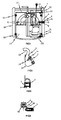
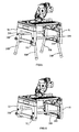
- Embodiment 1 As shown in Figure 1, Figure 2 and Figure 3, base 3 consists of a vertical frame and closing plates located in the middle of the vertical frame wherein the front and back sides of the upper part of the base have openings, and left side frame 32 and right side frame 31, respectively fixed to the vertical frame, are on the upper part of the base.
- Work table 11 used for installation of the saw blade unit is supported between left side frame 32 and right side frame 31 on base 3 and may be turned over by flip-over shaft 4 along axial line O-O.
- Small ends 41 are respectively set at the both ends of flip over shaft 4; small end 41, right side frame 31 and left side frame of base 3 are connected by connecting bolt 1, and wear-resistant connecting sleeves are arranged among the connecting bolt, the flip-over shaft and the left and right side frames.
- Left side frame 32 and right side frame 31 respectively have an upper foot pad 61 corresponding to the front side of shaft O-O, and left side frame 32 and right side frame 31 both have a lower foot pad 62 corresponding to the back side of shaft O-O.
- upper foot pad 61 and lower foot pad respectively have an inverted L-type foot pad bracket 8 and a foot pad body 6, wherein foot pad bracket 8 has a vertical part 81 and a horizontal part 82, vertical part 81 is fixed to the left side frame and the right side frame of base 3, horizontal part 82 being fixed to foot pad body 6.
- Front flange 111 and back flange 112 which are higher than the surface of work table 11, are respectively set at the front side and the back side of work table 11, wherein front flange 111 is straight and back flange 112 is curved.
- Front convex body 12 is set at the front flange corresponding to the side of work table 11
- back convex body 13 is set at the back flange corresponding to the side of work table 11
- front convex body 12 and back convex body are set at the same side of the work table.
- Front convex body 12 and back convex body 13 consists of bolt 10 and guide sleeve 15, which is fixed to the side of the work table along the same axis of bolt 10.
- the lower foot pad on one side of shaft O-O and under the work table supports the side of the work table
- the upper foot pad on the other side of shaft O-O overhangs the work table
- the work table may be orientated by means of the front convex body and the slope of the stop plate, so the saw blade unit on the work table can be used for normal cutting.
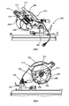
- saw blade unit 200 comprises a supporting arm 201 and the main body 202.
- Supporting arm 201 is fixedly set behind the turn plate, and the back end of the main body 202 is connected to supporting arm 201 by supporting shaft 203, so main body 202 may be moved up and down along supporting arm 203.
- the main body 202 contains a saw blade cover 204 acting as the shell, an actuating motor 205 arranged on one side of the saw blade cover 204 and a handle 206. Nearly half of circular saw blade 207 driven by actuating motor 205 is exposed outside the saw blade cover 204.
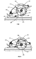
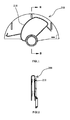
- slide way 210 is set on the side of guard 208. As shown in Figure 11 and Figure 12, slide way 210 has a convex rib structure and is perpendicular to the guard. The slide way has an evolvent structure, and it extends form the end nearer to the centre of the guard to the end farther from the centre of the guard in a direction opposite to the direction of opening of the guard.
- a guide wheel 218 is pin-jointed to saw blade cover 204, the pin-jointed shaft of guide wheel 218 is parallel to the axial line of circular saw blade 207, and guide wheel 218 is fit to guide chamfer 212 in the middle of the connecting rod and can roll along it.
- the guide section of the connecting rod and the rolling element set on the connecting rod are respectively on the two sides of the centre of the movable guard, and they are also at the end where the bearing is set on the connecting rod.
- the points of support on connecting rod 211 and supporting arm 202 are between the points of support of the saw blade cover and supporting arm and the pin-jointed position of guide wheel to the saw blade cover.
- the guard Under the load of spring the guard always tends to surround the blade. With the movement of the main body downwards around the supporting shaft, the guide wheel pin-jointed to the saw blade cover will roll along the guide chamfer in the middle section of the connecting rod, so the space between the end where a bearing is set on the connecting rod and the centre of the guard will gradually increase, which will cause the bearing to roll along the slide way on the side of the guard.
- the slide way extends from the end nearer to the centre of the guard to the end farther from the centre of the guard in the direction opposite to the direction of opening of the guard, and with downwards motion by the main body, the bearing at the end of the connecting rod will roll from the end nearer to the centre of the guard to the end farther from the centre of the guard, so the guard will gradually open with the downwards motion of the main body and the saw blade is exposed for cutting.
- the guard When the main body is raised, i.e., moved upwards, the guard will gradually close under the applied load of the pulling force, such that when the saw blade is not being used for cutting it will be covered to achieve the objectives of safety and protection.
- a locking trigger 214 is placed on the saw blade cover near the upper edge of the guard.
- upper hollow structure 301 and the lower hollow structure are respectively set on left side frame 32 and right side frame 31, upper hollow structure 301 having several crossed reinforcing bars.
- Left side frame 32 is connected to right side frame 31 by crosspiece 304, and connecting holes 305 are formed on the left side frame and the right side frame to fit crosspiece 304.
- crosspiece 304 When the two ends of crosspiece 304 are inserted into the connecting holes on the left side frame and the right side frame, they are anchored by screw 306.
- Two sets of leg orientation mechanisms are respectively positioned at the lower end of left side frame 32 and right side frame 31, each set of leg orientation mechanisms respectively including a vertical orientation slot 306 which extends generally vertically and a horizontal orientation slot 307 which extends generally horizontally, vertical orientation slot 306 and horizontal orientation slot 307 being integral with the left side frame and the right side frame.
- Vertical orientation slot 306 and the horizontal orientation slot are curved, and the vertical orientation slot slants outwards from top to bottom.
- the four horizontal orientation slots of the leg orientation devices on the left and right side frames are all positioned at the same level, the distance between the horizontal orientation slot on the back side of right side frame 31 and the horizontal orientation slot on the front side of right side frame 31 being equal to the diameter of the movable leg,
- the four movable legs 308 when the four movable legs 308 are orientated inside vertical orientation slot 306 with tightened bolts 310 and knobs 311, the four movable legs 308 respectively support the left side and the right side of the left and right side frames and consequently the work table as well.
- the four movable legs 308 when the four movable legs 308 are placed inside horizontal orientation slot 307 and bolts 310 and knobs 311 are tightened, all the lower ends of the four movable legs 308 being swung inwards, the four movable legs 308 are retracted in a manner suitable for packing and transport.
- the four movable legs 308 when the four movable legs 308 are orientated inside horizontal orientation slot 307 with tightened bolts 310 and knobs 311 and the lower ends of the four movable legs 308 are swung outwards, the four movable legs 308 can be used as handles.
- the space between the two handlers is relatively larger and thus ergonomic. Further, the relatively larger space between the movable legs allows handlers to see better during handling of the compound saw, thereby being convenient for handling.
Landscapes
- Life Sciences & Earth Sciences (AREA)
- Engineering & Computer Science (AREA)
- Mechanical Engineering (AREA)
- Wood Science & Technology (AREA)
- Forests & Forestry (AREA)
- Sawing (AREA)
- Lubricants (AREA)
Applications Claiming Priority (1)
| Application Number | Priority Date | Filing Date | Title |
|---|---|---|---|
| CNU2006201015166U CN2910497Y (zh) | 2006-03-09 | 2006-03-09 | 切割机工作台面翻转定位装置 |
Publications (1)
| Publication Number | Publication Date |
|---|---|
| EP1832368A1 true EP1832368A1 (de) | 2007-09-12 |
Family
ID=38132362
Family Applications (2)
| Application Number | Title | Priority Date | Filing Date |
|---|---|---|---|
| EP07103784A Not-in-force EP1832367B1 (de) | 2006-03-09 | 2007-03-08 | Kapp- und Gehrungssäge mit Schutzöffnungsvorrichtung |
| EP07103785A Withdrawn EP1832368A1 (de) | 2006-03-09 | 2007-03-08 | Leicht zu bedienende Kapp- und Gehrungssäge |
Family Applications Before (1)
| Application Number | Title | Priority Date | Filing Date |
|---|---|---|---|
| EP07103784A Not-in-force EP1832367B1 (de) | 2006-03-09 | 2007-03-08 | Kapp- und Gehrungssäge mit Schutzöffnungsvorrichtung |
Country Status (4)
| Country | Link |
|---|---|
| EP (2) | EP1832367B1 (de) |
| CN (1) | CN2910497Y (de) |
| AT (1) | ATE464145T1 (de) |
| DE (1) | DE602007005857D1 (de) |
Cited By (2)
| Publication number | Priority date | Publication date | Assignee | Title |
|---|---|---|---|---|
| CN103962634A (zh) * | 2013-02-06 | 2014-08-06 | 苏州宝时得电动工具有限公司 | 切割机 |
| CN103962634B (zh) * | 2013-02-06 | 2016-11-30 | 苏州宝时得电动工具有限公司 | 切割机 |
Families Citing this family (4)
| Publication number | Priority date | Publication date | Assignee | Title |
|---|---|---|---|---|
| US8424434B2 (en) | 2009-04-28 | 2013-04-23 | Robert Bosch Gmbh | Universal fence for a power table saw |
| CN107336033A (zh) * | 2017-05-31 | 2017-11-10 | 安徽铸星机械制造有限公司 | 一种可伸长的夹具底板 |
| CN107803950A (zh) * | 2017-11-28 | 2018-03-16 | 广西大学 | 一种多自由度切割平台 |
| CN112917164B (zh) * | 2021-01-29 | 2022-12-09 | 中建三局科创产业发展有限公司 | 一种直角钢弯折切割装置 |
Citations (2)
| Publication number | Priority date | Publication date | Assignee | Title |
|---|---|---|---|---|
| EP1614508A1 (de) * | 2004-07-07 | 2006-01-11 | BLACK & DECKER INC. | Ständer für tragbare Werkzeugmaschine |
| JP2006044069A (ja) * | 2004-08-04 | 2006-02-16 | Makita Corp | 切断機 |
Family Cites Families (1)
| Publication number | Priority date | Publication date | Assignee | Title |
|---|---|---|---|---|
| US6279442B1 (en) * | 1998-09-11 | 2001-08-28 | Chin-Chin Chang | Blade guard device for a sawing machine |
-
2006
- 2006-03-09 CN CNU2006201015166U patent/CN2910497Y/zh not_active Expired - Fee Related
-
2007
- 2007-03-08 AT AT07103784T patent/ATE464145T1/de active
- 2007-03-08 EP EP07103784A patent/EP1832367B1/de not_active Not-in-force
- 2007-03-08 DE DE602007005857T patent/DE602007005857D1/de active Active
- 2007-03-08 EP EP07103785A patent/EP1832368A1/de not_active Withdrawn
Patent Citations (2)
| Publication number | Priority date | Publication date | Assignee | Title |
|---|---|---|---|---|
| EP1614508A1 (de) * | 2004-07-07 | 2006-01-11 | BLACK & DECKER INC. | Ständer für tragbare Werkzeugmaschine |
| JP2006044069A (ja) * | 2004-08-04 | 2006-02-16 | Makita Corp | 切断機 |
Cited By (2)
| Publication number | Priority date | Publication date | Assignee | Title |
|---|---|---|---|---|
| CN103962634A (zh) * | 2013-02-06 | 2014-08-06 | 苏州宝时得电动工具有限公司 | 切割机 |
| CN103962634B (zh) * | 2013-02-06 | 2016-11-30 | 苏州宝时得电动工具有限公司 | 切割机 |
Also Published As
| Publication number | Publication date |
|---|---|
| CN2910497Y (zh) | 2007-06-13 |
| EP1832367B1 (de) | 2010-04-14 |
| ATE464145T1 (de) | 2010-04-15 |
| EP1832367A1 (de) | 2007-09-12 |
| DE602007005857D1 (de) | 2010-05-27 |
Similar Documents
| Publication | Publication Date | Title |
|---|---|---|
| US7752950B2 (en) | Electric miter saw | |
| US6119676A (en) | Saw having movable table and saw blade | |
| EP1925406A1 (de) | Werkbank für elektrische Werkzeuge | |
| EP2233235B1 (de) | Kreissäge mit Gleitmechanismus | |
| US9616587B2 (en) | Fence assembly for a miter saw | |
| EP2075078A2 (de) | Tischsäge | |
| US20050098010A1 (en) | Electric miter saw | |
| EP1832368A1 (de) | Leicht zu bedienende Kapp- und Gehrungssäge | |
| US20100212467A1 (en) | Slide-type cutting machine | |
| US20090301277A1 (en) | Saw With Moveable Material Support Surface | |
| US7228775B2 (en) | Sliding miter saw | |
| KR101027280B1 (ko) | 톱날의 위치가 조절되는 목재 재단장치 | |
| ITMI20090172U1 (it) | Trancia blocchi con leverismo a camma perfezionato. | |
| EP1533064B1 (de) | Elektrische Gehrungssäge | |
| JP4305058B2 (ja) | 帯鋸機 | |
| CN212177023U (zh) | 一键解锁的梯柱锁定机构 | |
| KR102133875B1 (ko) | 휴대용 절첩식 목공 재단 장치 | |
| CN207681381U (zh) | 一种钢筋切割机 | |
| CN101244470B (zh) | 便于搬运的复合锯 | |
| CN105437378B (zh) | 切割工具 | |
| CN222541174U (zh) | 一种具有防护结构的切割机 | |
| CN216940583U (zh) | 方便折叠的工作台架 | |
| CN223718425U (zh) | 压入式拉杆台锯 | |
| KR200291037Y1 (ko) | 마늘 줄기 절단기 | |
| CN210334141U (zh) | 一种建筑工程用钢筋切割装置 |
Legal Events
| Date | Code | Title | Description |
|---|---|---|---|
| PUAI | Public reference made under article 153(3) epc to a published international application that has entered the european phase |
Free format text: ORIGINAL CODE: 0009012 |
|
| AK | Designated contracting states |
Kind code of ref document: A1 Designated state(s): AT BE BG CH CY CZ DE DK EE ES FI FR GB GR HU IE IS IT LI LT LU LV MC MT NL PL PT RO SE SI SK TR |
|
| AX | Request for extension of the european patent |
Extension state: AL BA HR MK YU |
|
| AKX | Designation fees paid |
Designated state(s): AT BE BG CH CY CZ DE DK EE ES FI FR GB GR HU IE IS IT LI LT LU LV MC MT NL PL PT RO SE SI SK TR |
|
| 17P | Request for examination filed |
Effective date: 20080508 |
|
| 17Q | First examination report despatched |
Effective date: 20080613 |
|
| STAA | Information on the status of an ep patent application or granted ep patent |
Free format text: STATUS: THE APPLICATION IS DEEMED TO BE WITHDRAWN |
|
| 18D | Application deemed to be withdrawn |
Effective date: 20081024 |