EP1832392A1 - Kraftbetriebenes Handwerkzeug - Google Patents
Kraftbetriebenes Handwerkzeug Download PDFInfo
- Publication number
- EP1832392A1 EP1832392A1 EP06251191A EP06251191A EP1832392A1 EP 1832392 A1 EP1832392 A1 EP 1832392A1 EP 06251191 A EP06251191 A EP 06251191A EP 06251191 A EP06251191 A EP 06251191A EP 1832392 A1 EP1832392 A1 EP 1832392A1
- Authority
- EP
- European Patent Office
- Prior art keywords
- motor
- enclosure
- hand tool
- power hand
- connector
- Prior art date
- Legal status (The legal status is an assumption and is not a legal conclusion. Google has not performed a legal analysis and makes no representation as to the accuracy of the status listed.)
- Withdrawn
Links
Images


Classifications
-
- B—PERFORMING OPERATIONS; TRANSPORTING
- B25—HAND TOOLS; PORTABLE POWER-DRIVEN TOOLS; MANIPULATORS
- B25F—COMBINATION OR MULTI-PURPOSE TOOLS NOT OTHERWISE PROVIDED FOR; DETAILS OR COMPONENTS OF PORTABLE POWER-DRIVEN TOOLS NOT PARTICULARLY RELATED TO THE OPERATIONS PERFORMED AND NOT OTHERWISE PROVIDED FOR
- B25F5/00—Details or components of portable power-driven tools not particularly related to the operations performed and not otherwise provided for
- B25F5/008—Cooling means
-
- H—ELECTRICITY
- H02—GENERATION; CONVERSION OR DISTRIBUTION OF ELECTRIC POWER
- H02K—DYNAMO-ELECTRIC MACHINES
- H02K9/00—Arrangements for cooling or ventilating
- H02K9/22—Arrangements for cooling or ventilating by solid heat conducting material embedded in, or arranged in contact with, the stator or rotor, e.g. heat bridges
- H02K9/227—Heat sinks
-
- H—ELECTRICITY
- H02—GENERATION; CONVERSION OR DISTRIBUTION OF ELECTRIC POWER
- H02K—DYNAMO-ELECTRIC MACHINES
- H02K5/00—Casings; Enclosures; Supports
- H02K5/04—Casings or enclosures characterised by the shape, form or construction thereof
- H02K5/12—Casings or enclosures characterised by the shape, form or construction thereof specially adapted for operating in liquid or gas
-
- H—ELECTRICITY
- H02—GENERATION; CONVERSION OR DISTRIBUTION OF ELECTRIC POWER
- H02K—DYNAMO-ELECTRIC MACHINES
- H02K7/00—Arrangements for handling mechanical energy structurally associated with dynamo-electric machines, e.g. structural association with mechanical driving motors or auxiliary dynamo-electric machines
- H02K7/14—Structural association with mechanical loads, e.g. with hand-held machine tools or fans
- H02K7/145—Hand-held machine tool
Definitions
- the present invention relates to a power hand tool for use in a wet environment.
- the electric motor of a power hand tool can become very hot during operation, and motor cooling has always been a concern. Efficient motor cooling in power hand tools for wet use is difficult to achieve because the required waterproofing arrangement inherently hinders heat transfer.
- the subject invention seeks to mitigate or at least alleviate such a problem by providing a power hand tool improved in this aspect.
- a power hand tool comprising a body and an electric motor located in the body and having a shaft for driving a connector for connecting and driving an implement, the motor having a metal casing.
- An enclosure encloses the motor for protection against intrusion of liquid, which includes a thermally conductive part that is exposed to the exterior outside the body. Also included is a thermal conductor in contact with the motor casing and the enclosure part for conducting heat from the motor to the enclosure part for heat dissipation.
- the enclosure part is situated outside the body.
- the enclosure has an opening that is closed by the enclosure part.
- the enclosure part is positioned in close proximity to the connector.
- the enclosure part has an apertured portion through which the connector extends from inside the enclosure.
- the apertured portion is tubular and supports the connector for rotation.
- thermal conductor is in surface contact with an end wall of the motor casing through which the motor shaft projects.
- thermal conductor is secured by screws to the motor casing.
- thermal conductor is secured by screws to the enclosure part.
- the thermal conductor has a central part in contact with the motor casing and opposite side parts in contact with the enclosure part.
- the power hand tool includes a gearbox connected between the motor shaft and the connector, which is flanked by the side parts of the thermal conductor.
- the invention also provides a power hand tool comprising a body and an electric motor located in the body and having a shaft for driving a connector for connecting and driving an implement, the motor having a metal casing.
- An enclosure encloses the motor for protection against intrusion of liquid.
- a heat sink as at least part of the enclosure in contact with the motor casing for conducting heat from the motor within the enclosure and then dissipating the heat out of the enclosure.
- the invention further provides a power hand tool comprising a body, an electric motor located in the body and having a shaft for driving a connector for connecting and driving an implement, the motor having a metal motor casing, and an enclosure located within the body and having an open end, wherein the motor is disposed within the enclosure.
- a thermally conductive enclosure part engages and encloses the open end of the enclosure, protecting the motor against intrusion of liquid, the enclosure part being exposed outside of the body.
- a thermal conductor within the enclosure and in contact with the metal motor casing and the enclosure part for conducts heat from the motor to the enclosure part for heat dissipation.
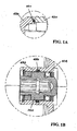
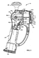
- an electric power hand tool embodying the invention which in this particular embodiment is a handheld polisher 10 (commonly known as scum buster) typically used for cleaning and publishing car bodies in a wet/soggy or waxy condition.
- the polisher 10 has a generally pistol-like plastic body 100 having a horizontal barrel 110 (as shown) that houses an electric motor 200 and including a depending handgrip 120 that holds a rechargeable battery 300.
- a plastic turning hand knob 130 is provided on the rear end of the barrel 110 so that the body 100 can be held firmly by both hands gripping the handgrip 120 and the knob 130.
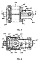
- the motor 200 is held co-axially inside a horizontally extending plastic capsule 400.
- the capsule 400 has a closed-ended rear portion 410 of a relatively smaller diameter locating the motor 200 and includes an expanded open-ended front portion 420 locating a speed-reduction gearbox 220 together with an aluminum bracket 240 that is a thermal conductor.
- the gearbox 200 is coupled with a shaft 210 of the motor 200 and includes an output socket 260 (at the end of a shaft) for connecting and driving a variety of cleaning and polishing implements, such as a brush 11, a piece of sponge 12 and a sheet of sander paper, with the use of an adaptor wherever necessary.
- the capsule 400 is closed by an aluminum end cap 430 which is thermally conductive and is secured by screws across the open end of the capsule front portion 420 to thereby seal off the capsule 400 with an O-ring 431 against intrusion of liquid.
- the output socket 260 extends outwards from inside the capsule 400 through a tubular central portion 432 of the end cap 430, which supports the socket 260 for rotation with the use of an O-ring 433 for sealing and a thrust race 434 for support.
- the capsule 400 with end cap 430 serves to act as a sealed enclosure enclosing the motor 200 and gearbox 220, etc. to protect them from water or liquid in general as well as dust for example. Sealing means for other electrical components are used wherever necessary.
- the capsule 400 is located in the barrel 110, with the end cap 430 situated foremost beyond the front end thereof.
- the motor 200 is connected by a pair of cables 201 via a pushbutton switch 204 to the battery 300 for power.
- the switch 204 is located in the front capsule portion 420 at its junction 415 with the rear portion 410.
- the cables 201 run from the motor 200 to the switch 204 and then out of the front portion 420 through a port 202 at the junction 415.
- a silicon tube 203 leading from the port 202 to the battery 300 acts as a waterproof passage for the cables 201 to reach the battery 300-
- the switch 204 includes a button 205 which protrudes from the junction 415, while being protected by a waterproof cap 206, for pressing by a spring-loaded trigger 207 via a hinged lever 208 to operate the switch 204.
- the gearbox 220 includes a gear shift pin 221 for changing the output speed, which is operated by a sliding knob 225 on the barrel 110 adjacent the hand knob 130.
- the shift pin 221 extends out of the capsule 400 at the junction 415 through a concertina sleeve 222 for waterproof protection, and is then engaged by the sliding knob 225 for operation thereby.
- the handgrip 120 has a hinged bottom lid 122 that sealingly closes its interior containing the battery 300.
- the battery 300 is connected by a pair of contact springs 302, to which the cables 201 from the power switch 204 are connected.
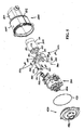
- the bracket 240 is of a rectangular U-shaped cross-section, having a flat circular central panel 241 and a pair of side limbs 242 extending from opposite left and right aides of the panel 241.
- the motor 200 has a metal casing 211 including a flat front end wall 212 which has two screw holes 213 and four vent holes 214 and through which the motor shaft 210 projects out.
- the bracket panel 241 has holes 243 and 244 matching with those holes 213 and 214 and includes a central hole 245.
- the bracket 240 is attached with its central panel 241 lying flat against and in surface contact with the front end wall 212 of the motor 200, with its central hole 245 accommodating the motor shaft 210, such that bracket 240 is in thermal contact with motor casing 211.
- the bracket holes 243 are aligned with the corresponding motor screw holes 213, through which respective screws 251 are tightened to secure the bracket 240 to the motor 200.
- the bracket holes 244 are aligned with the motor vent holes 214 to ensure that the latter remain exposed for venting.
- the side limbs 242 of the bracket 240 have respective free ends which extend straight to reach the end cap 430 and are folded inwardly each having two holes 246.
- the end cap 430 has on its inner surface four blind holes aligned with the bracket end holes 246, through which respective screws 252 are used to secure the bracket 240 and end cap 430 together such that they are in thermal contact with each other.
- the gearbox 220 is located in the bracket 240 and flanked by opposite side limbs 242 thereof, and is fixed in position by the end cap 430 upon connection of the end cap 430 to the bracket limbs 242.
- the bracket 240 acts as an internal heat sink for conducting heat from the motor 200 inside the capsule 400 to the end cap 430.
- the end cap 430 acts as an external heat sink for in turn conducting the motor heat out of the capsule 400 to thereby dissipate heat to the exterior outside the barrel 110.
- liquid detergent or wax
- the bracket 240 and end cap 430 together acts as a heat sink that conducts heat from the motor 200 within the enclosure 400/430 and then dissipates the heat out of the enclosure 400/430 by the end cap 430 being part thereof.
- the end cap 430 should be situated at least at an outer surface of the power tool body 100, which in this particular embodiment occupies the front end opening of the body 100. The efficiency of heat dissipation will be increased if the capsule 400 is also made of a heat sink material.
- the heat sink 240/430 may be made of any other high thermal conductivity material, whether it be metal or non-metal such as ceramic, for direct contact with the motor 200, and may be made in any shape, configuration and/or dimension, with or without cooling fins.
- the electric polisher 10 as described is made to be waterproof to one meter deep in water, but it is to be understood that the power tool of the subject invention may be made to be splash-proof only for a lower level of waterproof requirement.
Landscapes
- Engineering & Computer Science (AREA)
- Power Engineering (AREA)
- Mechanical Engineering (AREA)
- Manipulator (AREA)
Priority Applications (1)
| Application Number | Priority Date | Filing Date | Title |
|---|---|---|---|
| EP06251191A EP1832392A1 (de) | 2006-03-06 | 2006-03-06 | Kraftbetriebenes Handwerkzeug |
Applications Claiming Priority (1)
| Application Number | Priority Date | Filing Date | Title |
|---|---|---|---|
| EP06251191A EP1832392A1 (de) | 2006-03-06 | 2006-03-06 | Kraftbetriebenes Handwerkzeug |
Publications (1)
| Publication Number | Publication Date |
|---|---|
| EP1832392A1 true EP1832392A1 (de) | 2007-09-12 |
Family
ID=36572457
Family Applications (1)
| Application Number | Title | Priority Date | Filing Date |
|---|---|---|---|
| EP06251191A Withdrawn EP1832392A1 (de) | 2006-03-06 | 2006-03-06 | Kraftbetriebenes Handwerkzeug |
Country Status (1)
| Country | Link |
|---|---|
| EP (1) | EP1832392A1 (de) |
Cited By (4)
| Publication number | Priority date | Publication date | Assignee | Title |
|---|---|---|---|---|
| DE102008011291A1 (de) * | 2008-02-27 | 2009-09-03 | Marquardt Gmbh | Elektrogerät, insbesondere in der Art eines Elektrohandwerkzeugs |
| WO2011137549A1 (de) * | 2010-05-03 | 2011-11-10 | Mueller Peter A | Koppelbarer antrieb |
| US10998797B2 (en) | 2017-12-19 | 2021-05-04 | Tti (Macao Commercial Offshore) Limited | Electric motor assembly including end cap having heat sink for heat-generating electrical component |
| US12017336B2 (en) | 2019-06-24 | 2024-06-25 | Milwaukee Electric Tool Corporation | Power tools with high-emissivity heat sinks |
Citations (4)
| Publication number | Priority date | Publication date | Assignee | Title |
|---|---|---|---|---|
| US3525002A (en) * | 1968-10-16 | 1970-08-18 | Sunbeam Corp | Electric motor structure |
| GB1516578A (en) * | 1976-05-25 | 1978-07-05 | Itt Fluid Handling Ltd | Waterproof pump |
| GB2050213A (en) * | 1979-06-08 | 1981-01-07 | Bosch Gmbh Robert | A power tool housing |
| DE10313273A1 (de) * | 2003-03-24 | 2004-10-07 | Ebm-Papst Mulfingen Gmbh & Co. Kg | Elektromotor mit hoher IP-Schutzart |
-
2006
- 2006-03-06 EP EP06251191A patent/EP1832392A1/de not_active Withdrawn
Patent Citations (4)
| Publication number | Priority date | Publication date | Assignee | Title |
|---|---|---|---|---|
| US3525002A (en) * | 1968-10-16 | 1970-08-18 | Sunbeam Corp | Electric motor structure |
| GB1516578A (en) * | 1976-05-25 | 1978-07-05 | Itt Fluid Handling Ltd | Waterproof pump |
| GB2050213A (en) * | 1979-06-08 | 1981-01-07 | Bosch Gmbh Robert | A power tool housing |
| DE10313273A1 (de) * | 2003-03-24 | 2004-10-07 | Ebm-Papst Mulfingen Gmbh & Co. Kg | Elektromotor mit hoher IP-Schutzart |
Cited By (5)
| Publication number | Priority date | Publication date | Assignee | Title |
|---|---|---|---|---|
| DE102008011291A1 (de) * | 2008-02-27 | 2009-09-03 | Marquardt Gmbh | Elektrogerät, insbesondere in der Art eines Elektrohandwerkzeugs |
| WO2011137549A1 (de) * | 2010-05-03 | 2011-11-10 | Mueller Peter A | Koppelbarer antrieb |
| US9416864B2 (en) | 2010-05-03 | 2016-08-16 | Peter A. Mueller | Coupleable drive |
| US10998797B2 (en) | 2017-12-19 | 2021-05-04 | Tti (Macao Commercial Offshore) Limited | Electric motor assembly including end cap having heat sink for heat-generating electrical component |
| US12017336B2 (en) | 2019-06-24 | 2024-06-25 | Milwaukee Electric Tool Corporation | Power tools with high-emissivity heat sinks |
Similar Documents
| Publication | Publication Date | Title |
|---|---|---|
| US7109613B2 (en) | Power hand tool | |
| RU2591914C2 (ru) | Перезаряжаемый электроинструмент | |
| CN110251260B (zh) | 口腔扫描机 | |
| CN101925443B (zh) | 具有防尘装置的手持式电动工具 | |
| EP2062700B1 (de) | Mittelgriffbohrmaschinenkonstruktion und Montageverfahren | |
| EP0420473B1 (de) | Hand-Hochdruckreinigungsgerät | |
| CN103846884B (zh) | 手持式工具机 | |
| US20060202571A1 (en) | Scrubber | |
| JP2003245865A5 (de) | ||
| US12502760B2 (en) | Compact powered wrench | |
| EP1832392A1 (de) | Kraftbetriebenes Handwerkzeug | |
| US8653388B2 (en) | Switch devices for power tools | |
| JP6917577B2 (ja) | 電動工具 | |
| WO1997029664A1 (en) | Hand-held cleaning tool | |
| US7765631B2 (en) | Power tool | |
| CN114981039B (zh) | 具有用于可充电电池的保护防护支架装置的动力工具 | |
| HK1108667A (en) | Power hand tool | |
| US20060236473A1 (en) | Scrub brush implement | |
| JP2000052279A (ja) | 電動工具 | |
| CN222200026U (zh) | 角磨机和电动工具 | |
| HK1048728A2 (en) | Dust suction device for hand-held power tool | |
| JP7700010B2 (ja) | 電動工具 | |
| JP3183083U (ja) | 携帯式電動研磨装置 | |
| CN115083810A (zh) | 集成电子开关及电动工具 | |
| JP2002346953A (ja) | 電動工具 |
Legal Events
| Date | Code | Title | Description |
|---|---|---|---|
| PUAI | Public reference made under article 153(3) epc to a published international application that has entered the european phase |
Free format text: ORIGINAL CODE: 0009012 |
|
| AK | Designated contracting states |
Kind code of ref document: A1 Designated state(s): AT BE BG CH CY CZ DE DK EE ES FI FR GB GR HU IE IS IT LI LT LU LV MC NL PL PT RO SE SI SK TR |
|
| AX | Request for extension of the european patent |
Extension state: AL BA HR MK YU |
|
| 17P | Request for examination filed |
Effective date: 20080226 |
|
| 17Q | First examination report despatched |
Effective date: 20080416 |
|
| REG | Reference to a national code |
Ref country code: HK Ref legal event code: DE Ref document number: 1108667 Country of ref document: HK |
|
| AKX | Designation fees paid |
Designated state(s): DE FR GB |
|
| STAA | Information on the status of an ep patent application or granted ep patent |
Free format text: STATUS: THE APPLICATION IS DEEMED TO BE WITHDRAWN |
|
| 18D | Application deemed to be withdrawn |
Effective date: 20080827 |
|
| REG | Reference to a national code |
Ref country code: HK Ref legal event code: WD Ref document number: 1108667 Country of ref document: HK |