EP1832408B1 - Procédé et Machine de thermoformage avec mécanisme à genouillère - Google Patents
Procédé et Machine de thermoformage avec mécanisme à genouillère Download PDFInfo
- Publication number
- EP1832408B1 EP1832408B1 EP07004213A EP07004213A EP1832408B1 EP 1832408 B1 EP1832408 B1 EP 1832408B1 EP 07004213 A EP07004213 A EP 07004213A EP 07004213 A EP07004213 A EP 07004213A EP 1832408 B1 EP1832408 B1 EP 1832408B1
- Authority
- EP
- European Patent Office
- Prior art keywords
- thermoforming machine
- tool
- toggle lever
- toggle
- motion
- Prior art date
- Legal status (The legal status is an assumption and is not a legal conclusion. Google has not performed a legal analysis and makes no representation as to the accuracy of the status listed.)
- Not-in-force
Links
- 238000003856 thermoforming Methods 0.000 title claims abstract description 43
- 230000007246 mechanism Effects 0.000 title claims description 14
- 238000000034 method Methods 0.000 title claims description 5
- 230000033001 locomotion Effects 0.000 claims abstract description 48
- 229920001169 thermoplastic Polymers 0.000 claims abstract description 10
- 238000004080 punching Methods 0.000 claims description 14
- 239000002985 plastic film Substances 0.000 claims description 9
- 230000008878 coupling Effects 0.000 claims description 2
- 238000010168 coupling process Methods 0.000 claims description 2
- 238000005859 coupling reaction Methods 0.000 claims description 2
- 238000000465 moulding Methods 0.000 abstract description 9
- 239000004416 thermosoftening plastic Substances 0.000 abstract description 5
- 210000003127 knee Anatomy 0.000 description 4
- 229920006255 plastic film Polymers 0.000 description 4
- 230000005540 biological transmission Effects 0.000 description 3
- 229910000831 Steel Inorganic materials 0.000 description 2
- 230000008901 benefit Effects 0.000 description 2
- 238000001816 cooling Methods 0.000 description 2
- 238000010438 heat treatment Methods 0.000 description 2
- 239000010959 steel Substances 0.000 description 2
- 240000006829 Ficus sundaica Species 0.000 description 1
- 230000001133 acceleration Effects 0.000 description 1
- 230000002411 adverse Effects 0.000 description 1
- 230000008859 change Effects 0.000 description 1
- 238000006243 chemical reaction Methods 0.000 description 1
- 239000002131 composite material Substances 0.000 description 1
- 238000005520 cutting process Methods 0.000 description 1
- 230000001419 dependent effect Effects 0.000 description 1
- 238000006073 displacement reaction Methods 0.000 description 1
- 230000035622 drinking Effects 0.000 description 1
- 230000002349 favourable effect Effects 0.000 description 1
- 239000011888 foil Substances 0.000 description 1
- 230000000977 initiatory effect Effects 0.000 description 1
- 230000003993 interaction Effects 0.000 description 1
- 238000004519 manufacturing process Methods 0.000 description 1
- 235000013310 margarine Nutrition 0.000 description 1
- 239000003264 margarine Substances 0.000 description 1
- 230000004048 modification Effects 0.000 description 1
- 238000012986 modification Methods 0.000 description 1
- 239000004033 plastic Substances 0.000 description 1
- 238000003825 pressing Methods 0.000 description 1
- 230000008569 process Effects 0.000 description 1
- 230000001360 synchronised effect Effects 0.000 description 1
- 230000002123 temporal effect Effects 0.000 description 1
Images



Classifications
-
- B—PERFORMING OPERATIONS; TRANSPORTING
- B29—WORKING OF PLASTICS; WORKING OF SUBSTANCES IN A PLASTIC STATE IN GENERAL
- B29C—SHAPING OR JOINING OF PLASTICS; SHAPING OF MATERIAL IN A PLASTIC STATE, NOT OTHERWISE PROVIDED FOR; AFTER-TREATMENT OF THE SHAPED PRODUCTS, e.g. REPAIRING
- B29C51/00—Shaping by thermoforming, i.e. shaping sheets or sheet like preforms after heating, e.g. shaping sheets in matched moulds or by deep-drawing; Apparatus therefor
- B29C51/26—Component parts, details or accessories; Auxiliary operations
- B29C51/30—Moulds
- B29C51/38—Opening, closing or clamping means
-
- B—PERFORMING OPERATIONS; TRANSPORTING
- B26—HAND CUTTING TOOLS; CUTTING; SEVERING
- B26D—CUTTING; DETAILS COMMON TO MACHINES FOR PERFORATING, PUNCHING, CUTTING-OUT, STAMPING-OUT OR SEVERING
- B26D5/00—Arrangements for operating and controlling machines or devices for cutting, cutting-out, stamping-out, punching, perforating, or severing by means other than cutting
- B26D5/08—Means for actuating the cutting member to effect the cut
- B26D5/18—Toggle-link means
-
- B—PERFORMING OPERATIONS; TRANSPORTING
- B26—HAND CUTTING TOOLS; CUTTING; SEVERING
- B26F—PERFORATING; PUNCHING; CUTTING-OUT; STAMPING-OUT; SEVERING BY MEANS OTHER THAN CUTTING
- B26F1/00—Perforating; Punching; Cutting-out; Stamping-out; Apparatus therefor
- B26F1/38—Cutting-out; Stamping-out
- B26F1/40—Cutting-out; Stamping-out using a press, e.g. of the ram type
Definitions
- the invention relates to a thermoforming machine and a method for operating a thermoforming machine for molding and stamping articles of a thermoplastic plastic film having an at least two-part tool, of which at least one of each supported by a tool table tools in an opening and closing direction by means of a moving member is adjustable, wherein the moving element consists of two to a central plane of at least a portion of the thermoforming machine mirror-inverted knee lever systems.
- thermoforming machines plastic articles (for example, margarine bowls, drinking cups, container lids) made of thermoplastic plastic films and composite films are produced between the relatively movable parts of a tool.
- the articles are shaped by pressing the heated film with compressed air or vacuum into the mold cavity, then punched and then with the tool in the open position out of this and into a downstream one Stacking and counting device is promoted.
- the upper tool is as well as the lower tool attached to a respective height-adjustable table, so that both tool parts are adjustable.
- thermoforming machine of the generic type is known from CH 399 724 known.
- the tool can be periodically closed and reopened, regardless of whether a pure forms, ie without punching or combined molding and punching of the article should be done or in a machine station only a punching of the already formed article from the plastic film to be performed , there are mirrored opposite each other two knee lever systems provided. These are each acted upon by a laterally arranged, pivotably mounted pneumatic cylinder, which acts with its piston rod centrally on the toggle lever of the toggle lever pair.
- the toggle levers are arranged in the area of the machine center and hinged at the top of a fixed bearing and at the bottom of the mold carrier on a bearing pin. The thus become known drive system only allows low cycle rates and is not suitable to absorb especially occurring during punching high lateral forces.
- roller spindle drives must be located in the middle of the tool or tool table because of the necessary central force application.
- the so-called pre-stretchers must be arranged, which performs a mechanical pre-forming of the heated plastic film.
- the pre-straightener is especially needed for high items. If the pre-expander is not - which is expensive - integrated in the tool, it must be positioned centrally or centrally in the thermoforming machine, so that the appropriate space must be available here.
- the pre-straightener must be able to perform an independent of the movement of the tool table movement in the rule.
- the path of the table with the tool is only a few tenths of a millimeter, with the direction of rotation of the drive or the travel of the cylinder is the same.
- the film is now punched through, after which a second stop is required, because the movement of the drives must be reversed so that they return to their original position, where followed by the initiation of a new cycle a third stop.
- Significant time losses occur due to deceleration and acceleration ramps, which is caused by run-up the engines forcibly expires, or by reversing the compressed air to the other piston surface in the cylinders.
- Another embodiment of the movement element for a tool part provides that a servomotor actuates a toggle lever system via a gear arrangement, which also moves the tool tables into the required position.
- the two rectified toggle lever systems are moved by a connecting rod in the same direction and simultaneously.
- This toggle lever system has the disadvantage that with a single drive both rectified toggle lever pairs must be moved in a direction perpendicular to the opening and closing movement of the tool part. This creates inertia forces that act perpendicular to the opening and closing movement of the machine, resulting in a tilting of the entire forming or stamping station.
- the guide columns of the tool parts are not able to absorb these forces and deformations without interference.
- the negative consequence is not only a higher wear on the guide columns and bushes, but also the service life of the strip steel for cutting the articles are considerably lower.
- the parallelism of the two tool halves of great importance which is affected by the high lateral mass forces. Therefore, thermoforming machines of this type are operable only with a limited clock frequency.
- Another disadvantage of this design is that a conversion of the machine must be made for very different opening and closing strokes.
- the invention is therefore based on the object to provide a thermoforming machine of the type mentioned without these disadvantages, which allows a high clock frequency, without disturbing lateral forces due to the toggle lever mass forces works and finally leaves sufficient space for the arrangement of a pre-stretchers, and to propose a method for operating such a thermoforming machine.
- the toggle systems are each movable by a drive motor via at least one crank, the drive motors are driven in opposite directions in each phase of movement and arranged together with the cranks on the side remote from the center plane side of the toggle lever system so that in the area the center plane results in a range free of motion elements.
- the drive system As an essential difference to the known drive systems and contrast great advantage can be realized with only two stop positions due to the inventive measures the drive system.
- the stop before the molding time to cool the product must also be maintained. But this is so that it takes place according to the thickness or residual thickness (about 0.3 mm) after the blanking of the film just before the top dead center of the crank mechanism.
- the drive After the cooling process is completed in the tool, the drive is restarted, continues driving it at the same time punching it top dead center and then without reversing in the same direction of rotation of the drives, so that the tool is opened. Only then will a second stop be required for a new duty cycle with reversal of the direction of rotation of the drives, which in turn will then run in opposite directions.
- the drive motors - possibly together with the associated gearbox - can be arranged laterally on the thermoforming machine and the center region of the machine is completely free of drive means for the tool movement can be held. This makes it possible to arrange mechanical pre-stretchers in the middle area, where they are needed; there is enough space for this.
- Both a lower tool table and an upper tool table can each be provided with a movement element.
- Each toggle lever system may consist of two spaced toggle levers, each toggle being moved by a crank.
- the parallel guidance of the tool part is ensured in two mutually perpendicular directions transverse to the opening and closing direction of the tool.
- the drive motor is preferably arranged together with a transmission and the bearing for the at least one crank in or on a housing.
- thermoforming machine may also be only part of a number of stations used in the manufacture of thermoformed articles. Therefore, according to one embodiment, it is provided that the movement element is designed for the combined molding of articles made of the thermoplastic film and punching of the articles made of the thermoplastic film. Alternatively, however, it can also be provided that the movement element for exclusively punching out the articles formed from the thermoplastic film is formed from the same. The introduction of holes in the article is realized with an additional punching station of this kind.
- drive motors are mainly servomotors or three-phase motors used, but in particular also torque motors that act without gear on the eccentric.
- thermoforming machine it is achieved that a high number of cycles of the thermoforming machine is possible. It can achieve up to 85 cycles per minute and more, which means an increase of about 40% over conventional drive arrangements.
- the drive system is absolutely free of lateral forces, d. H. Mass forces that are transverse to the opening and closing movement of the tool. Sideways mass forces cancel out throughout the system, keeping the machine stable.
- thermoforming machine remains free, so that here a pre-stretchers can be accommodated without problems, without coming into collisions with the moving element.
- thermoforming machine 1 is shown, are made with the article 2 of a thermoplastic film 3.
- the film 3 is heated and placed between two open tool tables 4, 5, each carrying a tool half 23, 24 fastened thereon.
- both tool tables 4, 5 are arranged to be movable relative to a machine frame 15, ie both tool tables 4, 5 move together with their tool halves 23, 24 vertically in an opening and closing direction A on guide columns 16.
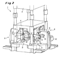
- each toggle lever system 8, 9 is - as out Fig. 2 evident - From two toggle levers 12 and 13, one behind the other in the direction normal to the plane of the Fig. 1 are arranged.
- the toggle levers 12, 13 consist essentially of two hingedly interconnected levers, which are articulated both below and above the machine stand 15 and the tool table 4, 5.
- each toggle lever system 8, 9 has its own crank 11, which is articulated on an eccentric 19; the directions of rotation are in Fig. 1 indicated by arrows.
- the eccentric 19 is mounted in a gear 14 and is driven by a drive motor 10.
- the drive motor 10 is preferably a servomotor for which precise rotational movements can be specified.
- the drive motors 10 are each driven so that the two mirror-inverted motors rotate in opposite directions to each other, as in the FIGS. 1 and 4 indicated by the direction of rotation arrows 21 a, 21 b and 22 a, 22 b. This ensures that mass forces of the toggle lever systems 8, 9 cancel in the direction transverse to the opening and closing direction A and thus no high loads on the guide columns 16 are exercised.
- the system consisting of drive motor 10, optionally arranged between the drive motor 10 and eccentric 19 gear 14, eccentric 19 and crank 11 forms a crank mechanism, which operates the toggle 12, 13.
- the rotational movement or the torque for the toggle levers 12, 13 can be generated either via two individual servo or three-phase motors with downstream gearboxes or via only one gearbox with two outputs and a drive motor 10 mounted centrally on the gearbox.
- a torque motor can also be used , whereby the transmission between the engine 10 and eccentric 19 can be dispensed with.
- the directions of rotation of the output shafts in the individual drives are in opposite directions.
- the synchronization of the rotational movements of both sides of the middle plane 7 arranged drive motors 10 can be done in the so-called “master-slave operation".
- the respective required position adjustment of both motors 10 is made via a PLC machine control and located on the drive motors 10 incremental or absolute encoders, which is already known as such on the basis of the available electronic means (also known under the term "electronic wave”) ,
- Fig. 3 For some system parameters of the thermoforming machine, the curve over the turning path or the time is shown. On the abscissa, the angle of rotation of the eccentric 19 of the crank mechanism runs. Attention is in this case to the movement of the lower workbench 4, referred to as "s-bottom" and shown with the solid line, the thicker solid line I the startup of the tool table 4, ie closing the tool, for example 202 °, and also thicker solid line II shutting down the tool table 4, for example, 158 °, to illustrate the opening of the tool.
- the degrees entered on the abscissa represent the first working cycle from 0 to 180 ° and the second working cycle from 180 ° to 360 °.
- crank mechanism is designed to maintain the same direction of rotation for each cycle as through Fig. 4 illustrated in which the toggle levers 12, 13 of the toggle lever systems 8, 9 are shown in the initial positions before the rotary movement, in accordance with a) and c) - in each case based on the position of the lower tool table 4 - at bottom dead center and b) and d) at top dead center.
- the sequence of movements or working cycle is such that the lower tool table 4 has assumed its position according to a) at bottom dead center, in which it moves by turning it down in the exemplary embodiment 158 ° with opposing directions (compare arrow 21a in clockwise direction and arrow 21b in counterclockwise direction) the two crank drives is reached, wherein the closing of the tool by raising the lower tool table 4 by 202 ° takes place with the same opposite movement (see b)).
- cranks 11 are always at the time of punching out the film, i. then, when the toggle levers 12, 13 take their stretched in the top dead center end positions according to b) and d) position, run centrally to the two toggle levers 12, 13, thus perpendicular to these.
- the unavoidable, high side forces F, as indicated by arrow in a), are thereby canceled.
- thermoforming machine has at least one station and a maximum of three stations, wherein in each case two movable tables are provided, which receive the respective mold halves, which must drive the respective Malawitischhub continuously depending on the deformation direction of the article.
- the travel of the tool parts can be adjusted continuously without modification.
- thermoforming machine In the center region of the proposed thermoforming machine remains a free area B (s. Fig. 1 ), in which the mechanical pre-stretching device or pre-stretching drive 20 can be easily arranged in the upper tool 5.
Landscapes
- Engineering & Computer Science (AREA)
- Mechanical Engineering (AREA)
- Life Sciences & Earth Sciences (AREA)
- Forests & Forestry (AREA)
- Blow-Moulding Or Thermoforming Of Plastics Or The Like (AREA)
- Moulds For Moulding Plastics Or The Like (AREA)
- Press Drives And Press Lines (AREA)
- Perforating, Stamping-Out Or Severing By Means Other Than Cutting (AREA)
Claims (9)
- Machine de thermoformage (1) pour façonner et découper des articles (2) en un film thermoplastique (3), laquelle comporte un outil en au moins deux éléments (23, 24) dont au moins l'un des outils (23, 24) portés chacun par un plateau porte-outils (4, 5) est réglable dans une direction d'ouverture et de fermeture (A) au moyen d'un élément de déplacement (6), l'élément de déplacement (6) consistant dans deux systèmes de leviers à genouillère (8, 9) disposés en symétrie spéculaire par rapport à un plan central (7) d'au moins une partie de la machine de thermoformage (1),
caractérisée en ce que
les systèmes de leviers à genouillère (8,9) sont déplaçables chacun par un moteur d'entraînement (10) via une manivelle (11), en ce que dans chaque phase de déplacement, les moteurs d'entraînement (10) sont entraînés en sens mutuellement opposé et sont disposés avec les manivelles (11) sur le côté opposé au plan central (7) du système de leviers à genouillère (8, 9) de sorte à ce qu'il en résulte une zone libre (B) d'éléments de déplacement (6) dans la zone du plan central (7). - Machine de thermoformage selon la revendication 1,
caractérisée en ce que
les manivelles (11) sont articulées d'une part sur les systèmes de leviers à genouillère (8, 9) et d'autre part sur des transmissions (14) des moteurs d'entraînement (10) de sorte que les leviers (11) ne s'étendent au centre des leviers à genouillère (12, 13) que lorsque le système de leviers à genouillère (8, 9) est étiré. - Machine de thermoformage selon la revendication 1 ou 2,
caractérisée en ce que,
aussi bien un plateau porte-outils inférieur (4) qu'un plateau porte-outils supérieur (5) est muni d'un élément de déplacement (6). - Machine de thermoformage selon l'une quelconque des revendications 1 à 3, caractérisée en ce que
chaque système de leviers à genouillère (8, 9) consiste dans deux leviers à genouillère (12, 13) disposés à une distance mutuelle, chaque levier à genouillère (12, 13) étant relié à un levier (11). - Machine de thermoformage selon l'une quelconque des revendications 1 à 4, caractérisée en ce que
le moteur d'entraînement (10) est disposé, ensemble avec la transmission (14) et le logement pour au moins un levier (11) dans ou sur un carter (14). - Machine de thermoformage selon l'une quelconque des revendications 1 à 5, caractérisée en ce que
le déplacement des angles de rotation des deux moteurs d'entraînement (10) est accouplé. - Machine de thermoformage selon la revendication 6, caractérisée en ce que
l'accouplement des deux moteurs d'entraînement (10) s'effectue par des moyens électroniques. - Machine de thermoformage selon l'une quelconque des revendications 1 à 7, caractérisée en ce que
les moteurs d'entraînement (10) sont des servomoteurs, des moteurs Torque ou des moteurs triphasés. - Procédé de thermoformage pour faire fonctionner une machine de thermoformage (1) selon l'une quelconque des revendications 1 à 8, pour façonner et découper des articles (2) en un film thermoplastique (3), laquelle comporte un outil en au moins deux éléments (23, 24) dont au moins l'un des outils (23, 24) portés chacun par un plateau porte-outils (4, 5) est réglable dans une direction d'ouverture et de fermeture (A) au moyen d'un élément de déplacement (6), l'élément de déplacement (6) consistant dans deux systèmes de leviers à genouillère (8, 9) disposés en symétrie spéculaire par rapport à un plan central (7) d'au moins une partie de la machine de thermoformage (1),
les systèmes de leviers à genouillère (8, 9) étant actionnés par des commandes d'admission par bielle-manivelle (10, 11, 19) avec des angles de rotation réglés différemment dans les cycles de déplacement individuels pour l'ouverture et la fermeture des plateaux porte-outils (4, 5), les cycles de déplacement étant pourtant divisés en parties individuelles et par des vitesses de rotation différentes dans les parties individuelles, la totalité du déplacement étant maintenue constante en somme.
Applications Claiming Priority (2)
| Application Number | Priority Date | Filing Date | Title |
|---|---|---|---|
| DE102006011039 | 2006-03-08 | ||
| DE102006019532A DE102006019532A1 (de) | 2006-03-08 | 2006-04-27 | Thermoformmaschine |
Publications (3)
| Publication Number | Publication Date |
|---|---|
| EP1832408A2 EP1832408A2 (fr) | 2007-09-12 |
| EP1832408A3 EP1832408A3 (fr) | 2009-02-18 |
| EP1832408B1 true EP1832408B1 (fr) | 2010-09-22 |
Family
ID=38162297
Family Applications (1)
| Application Number | Title | Priority Date | Filing Date |
|---|---|---|---|
| EP07004213A Not-in-force EP1832408B1 (fr) | 2006-03-08 | 2007-03-01 | Procédé et Machine de thermoformage avec mécanisme à genouillère |
Country Status (4)
| Country | Link |
|---|---|
| US (1) | US7510389B2 (fr) |
| EP (1) | EP1832408B1 (fr) |
| AT (1) | ATE482071T1 (fr) |
| DE (2) | DE102006019532A1 (fr) |
Families Citing this family (15)
| Publication number | Priority date | Publication date | Assignee | Title |
|---|---|---|---|---|
| JP2008043970A (ja) * | 2006-08-14 | 2008-02-28 | Ihi Corp | サーボプレスとその運転方法 |
| US8360273B2 (en) * | 2008-10-08 | 2013-01-29 | Dixie Consumer Products Llc | Cutlery utensil dispenser |
| US8356990B2 (en) * | 2009-05-01 | 2013-01-22 | Brian Keeley | Toggle drive system for driving in a thermoforming press |
| TW201200326A (en) * | 2010-03-29 | 2012-01-01 | Automation Tooling Syst | Mechanism and system for clamping |
| DE102010054976A1 (de) * | 2010-06-07 | 2011-12-08 | Kiefel Gmbh | Thermoformstation, Thermoformanlage, Verfahren zum Formen oder Stanzen sowie hergestellte Artikel |
| ES2597703T3 (es) | 2012-05-24 | 2017-01-20 | Multivac Sepp Haggenmüller Gmbh & Co Kg | Equipo de elevación para una máquina de envasado |
| US10270709B2 (en) | 2015-06-26 | 2019-04-23 | Microsoft Technology Licensing, Llc | Allocating acceleration component functionality for supporting services |
| US9792154B2 (en) | 2015-04-17 | 2017-10-17 | Microsoft Technology Licensing, Llc | Data processing system having a hardware acceleration plane and a software plane |
| US10511478B2 (en) | 2015-04-17 | 2019-12-17 | Microsoft Technology Licensing, Llc | Changing between different roles at acceleration components |
| US10296392B2 (en) | 2015-04-17 | 2019-05-21 | Microsoft Technology Licensing, Llc | Implementing a multi-component service using plural hardware acceleration components |
| US10216555B2 (en) | 2015-06-26 | 2019-02-26 | Microsoft Technology Licensing, Llc | Partially reconfiguring acceleration components |
| WO2018035988A1 (fr) * | 2016-08-25 | 2018-03-01 | 江苏贸隆机械制造有限公司 | Machine de coupe à grande vitesse de masque facial |
| DE112018005363A5 (de) * | 2017-09-21 | 2020-10-01 | Kiefel Gmbh | Stanzmaschine, stanzwerkzeug-rüstsystem für eine stanzmaschine, stanzwerkzeug, verfahren zum einrüsten einer stanzmaschine, verfahren zum rüsten einer stanzmaschine, verfahren zum betreiben einer stanzmaschine sowie verwendung eines stanzunterwerkzeugs |
| CN111098358A (zh) * | 2019-12-25 | 2020-05-05 | 义乌融鹄电子科技有限公司 | 一种pc透镜自动切料机构 |
| CN112743892B (zh) * | 2020-12-23 | 2021-08-27 | 无锡市欧凯电子有限公司 | 结点正置选点冲压控制方法及压力机 |
Family Cites Families (13)
| Publication number | Priority date | Publication date | Assignee | Title |
|---|---|---|---|---|
| US2269758A (en) * | 1938-10-12 | 1942-01-13 | Noronha Rubber Products Corp D | Mechanical press |
| GB807760A (en) * | 1955-06-24 | 1959-01-21 | William Frank Golding | Improvements in or relating to power presses |
| NL285442A (fr) * | 1961-11-13 | 1900-01-01 | ||
| US4158539A (en) * | 1978-05-10 | 1979-06-19 | Leesona Corporation | Thermoforming machine with variable mold closed cycle |
| US4608009A (en) * | 1984-05-23 | 1986-08-26 | John Brown Inc. | Thermoforming equipment for differential pressure forming products in thermoplastic material |
| US4588364A (en) * | 1985-04-01 | 1986-05-13 | Husky Injection Molding Systems Ltd. | Clamp mechanism |
| DE3604255A1 (de) | 1986-02-11 | 1987-08-13 | Illig Maschinenbau Adolf | Kniehebelantrieb |
| JP2584287B2 (ja) * | 1988-08-29 | 1997-02-26 | ファナック株式会社 | トグル式型締装置 |
| US5176923A (en) * | 1989-07-24 | 1993-01-05 | Ito Kogyo Kabushiki Kaisha | Mold-pressing apparatus incorporating electric servo motor and linking mechanism |
| DE19848628C2 (de) | 1998-10-22 | 2002-09-12 | Gabler Gmbh Maschbau | Verfahren zum Betreiben einer Thermoformmaschine |
| US6200122B1 (en) * | 1999-08-03 | 2001-03-13 | Brown Machine, Llc. | Thermoforming apparatus with improved press |
| US6477945B1 (en) * | 1999-09-07 | 2002-11-12 | Aida Engineering, Ltd. | Double-action mechanical press |
| AT414224B (de) * | 2002-07-19 | 2006-10-15 | Engel Austria Gmbh | Schliesseinheit einer zweiplattenspritzgiessmaschine |
-
2006
- 2006-04-27 DE DE102006019532A patent/DE102006019532A1/de not_active Withdrawn
-
2007
- 2007-03-01 EP EP07004213A patent/EP1832408B1/fr not_active Not-in-force
- 2007-03-01 AT AT07004213T patent/ATE482071T1/de active
- 2007-03-01 DE DE502007005118T patent/DE502007005118D1/de active Active
- 2007-03-08 US US11/715,701 patent/US7510389B2/en not_active Expired - Fee Related
Also Published As
| Publication number | Publication date |
|---|---|
| US20070210487A1 (en) | 2007-09-13 |
| DE102006019532A1 (de) | 2007-09-20 |
| US7510389B2 (en) | 2009-03-31 |
| ATE482071T1 (de) | 2010-10-15 |
| EP1832408A2 (fr) | 2007-09-12 |
| EP1832408A3 (fr) | 2009-02-18 |
| DE502007005118D1 (de) | 2010-11-04 |
Similar Documents
| Publication | Publication Date | Title |
|---|---|---|
| EP1832408A2 (fr) | Machine de formage thermique avec mécanisme à genouillère | |
| DE60214802T2 (de) | Verfahren und Werkzeugschliesseinheit für Spritzgiessmaschinen | |
| EP1497099B1 (fr) | Installation de thermoformage pour la production de corps faconnes a partir d'un film de plastique, et procede de production de tels corps | |
| DE10325826A1 (de) | Einrichtung und Verfahren zum Antreiben einer Presse | |
| WO2009156199A1 (fr) | Entraînement direct de presse | |
| EP0786297A1 (fr) | Mécanisme d'entraînement pour une machine de formage | |
| WO2004037527A2 (fr) | Dispositif pour estamper, matricer et/ou deformer des elements plats | |
| WO2017084952A1 (fr) | Presse à course imposée comportant un coulisseau | |
| DE102009045543B4 (de) | Thermoformanlage und Antriebseinheit sowie ein Verfahren zum Betreiben der Thermoformanlage | |
| DE102012217276B4 (de) | Schmiedepresse und Verfahren zum Steuern dieser | |
| WO2006045279A2 (fr) | Système d'entraînement d'une presse de formage | |
| DE2337793A1 (de) | Verfahren und vorrichtung zum warmformen mit zusammenpassenden pressenteilen | |
| EP3209492B1 (fr) | Dispositif d'entraînement de presse et presse équipée d'un dispositif d'entraînement de presse | |
| WO2011064054A1 (fr) | Machine de façonnage, en particulier servopresse | |
| DE10218511B4 (de) | Thermoformanlage zur Herstellung von Formkörpern aus Kunststofffolie, sowie Verfahren zu deren Herstellung | |
| DE102015117200B4 (de) | Prägepresse und Verfahren zu deren Betrieb | |
| WO2017186234A1 (fr) | Presse-transfert pourvue d'un serre-flan en c | |
| DE19837632C2 (de) | Stauchpresse | |
| DE10218486B4 (de) | Thermoformanlage zur Herstellung von Formkörpern aus Kunststoffolie, sowie Verfahren zu deren Herstellung | |
| EP2483065A1 (fr) | Procédé pour déplacer une unité de façonnage d'une machine | |
| EP3584225A1 (fr) | Procédé de commande de l'entraînement rotatif d'une machine de moulage à chaud | |
| EP2529922B1 (fr) | Dispositif d'actionnement pour un automate de presse, de découpe ou de déformage | |
| EP1981792A1 (fr) | Dispositif de traitement d'une bande de matiere | |
| DE10253993A1 (de) | Faltmaschine mit Antriebsschwinge | |
| DE102017221281A1 (de) | Vorrichtung und Verfahren zum Betrieb einer Stranggießeinrichtung |
Legal Events
| Date | Code | Title | Description |
|---|---|---|---|
| PUAI | Public reference made under article 153(3) epc to a published international application that has entered the european phase |
Free format text: ORIGINAL CODE: 0009012 |
|
| AK | Designated contracting states |
Kind code of ref document: A2 Designated state(s): AT BE BG CH CY CZ DE DK EE ES FI FR GB GR HU IE IS IT LI LT LU LV MC MT NL PL PT RO SE SI SK TR |
|
| AX | Request for extension of the european patent |
Extension state: AL BA HR MK YU |
|
| PUAL | Search report despatched |
Free format text: ORIGINAL CODE: 0009013 |
|
| AK | Designated contracting states |
Kind code of ref document: A3 Designated state(s): AT BE BG CH CY CZ DE DK EE ES FI FR GB GR HU IE IS IT LI LT LU LV MC MT NL PL PT RO SE SI SK TR |
|
| AX | Request for extension of the european patent |
Extension state: AL BA HR MK RS |
|
| 17P | Request for examination filed |
Effective date: 20090801 |
|
| 17Q | First examination report despatched |
Effective date: 20090921 |
|
| AKX | Designation fees paid |
Designated state(s): AT BE BG CH CY CZ DE DK EE ES FI FR GB GR HU IE IS IT LI LT LU LV MC MT NL PL PT RO SE SI SK TR |
|
| GRAP | Despatch of communication of intention to grant a patent |
Free format text: ORIGINAL CODE: EPIDOSNIGR1 |
|
| RTI1 | Title (correction) |
Free format text: THERMOFORMING METHOD AND THERMOFORMING MACHINE WITH TOGGLE MECHANISM |
|
| GRAS | Grant fee paid |
Free format text: ORIGINAL CODE: EPIDOSNIGR3 |
|
| GRAA | (expected) grant |
Free format text: ORIGINAL CODE: 0009210 |
|
| AK | Designated contracting states |
Kind code of ref document: B1 Designated state(s): AT BE BG CH CY CZ DE DK EE ES FI FR GB GR HU IE IS IT LI LT LU LV MC MT NL PL PT RO SE SI SK TR |
|
| REG | Reference to a national code |
Ref country code: GB Ref legal event code: FG4D Free format text: NOT ENGLISH |
|
| REG | Reference to a national code |
Ref country code: CH Ref legal event code: EP |
|
| REG | Reference to a national code |
Ref country code: IE Ref legal event code: FG4D Free format text: LANGUAGE OF EP DOCUMENT: GERMAN |
|
| REF | Corresponds to: |
Ref document number: 502007005118 Country of ref document: DE Date of ref document: 20101104 Kind code of ref document: P |
|
| REG | Reference to a national code |
Ref country code: CH Ref legal event code: NV Representative=s name: SCHMAUDER & PARTNER AG PATENT- UND MARKENANWAELTE |
|
| PG25 | Lapsed in a contracting state [announced via postgrant information from national office to epo] |
Ref country code: LT Free format text: LAPSE BECAUSE OF FAILURE TO SUBMIT A TRANSLATION OF THE DESCRIPTION OR TO PAY THE FEE WITHIN THE PRESCRIBED TIME-LIMIT Effective date: 20100922 Ref country code: FI Free format text: LAPSE BECAUSE OF FAILURE TO SUBMIT A TRANSLATION OF THE DESCRIPTION OR TO PAY THE FEE WITHIN THE PRESCRIBED TIME-LIMIT Effective date: 20100922 |
|
| REG | Reference to a national code |
Ref country code: NL Ref legal event code: VDEP Effective date: 20100922 |
|
| LTIE | Lt: invalidation of european patent or patent extension |
Effective date: 20100922 |
|
| PG25 | Lapsed in a contracting state [announced via postgrant information from national office to epo] |
Ref country code: SI Free format text: LAPSE BECAUSE OF FAILURE TO SUBMIT A TRANSLATION OF THE DESCRIPTION OR TO PAY THE FEE WITHIN THE PRESCRIBED TIME-LIMIT Effective date: 20100922 Ref country code: PL Free format text: LAPSE BECAUSE OF FAILURE TO SUBMIT A TRANSLATION OF THE DESCRIPTION OR TO PAY THE FEE WITHIN THE PRESCRIBED TIME-LIMIT Effective date: 20100922 |
|
| PG25 | Lapsed in a contracting state [announced via postgrant information from national office to epo] |
Ref country code: SE Free format text: LAPSE BECAUSE OF FAILURE TO SUBMIT A TRANSLATION OF THE DESCRIPTION OR TO PAY THE FEE WITHIN THE PRESCRIBED TIME-LIMIT Effective date: 20100922 Ref country code: GR Free format text: LAPSE BECAUSE OF FAILURE TO SUBMIT A TRANSLATION OF THE DESCRIPTION OR TO PAY THE FEE WITHIN THE PRESCRIBED TIME-LIMIT Effective date: 20101223 Ref country code: LV Free format text: LAPSE BECAUSE OF FAILURE TO SUBMIT A TRANSLATION OF THE DESCRIPTION OR TO PAY THE FEE WITHIN THE PRESCRIBED TIME-LIMIT Effective date: 20100922 |
|
| REG | Reference to a national code |
Ref country code: IE Ref legal event code: FD4D |
|
| PG25 | Lapsed in a contracting state [announced via postgrant information from national office to epo] |
Ref country code: IE Free format text: LAPSE BECAUSE OF FAILURE TO SUBMIT A TRANSLATION OF THE DESCRIPTION OR TO PAY THE FEE WITHIN THE PRESCRIBED TIME-LIMIT Effective date: 20100922 |
|
| PG25 | Lapsed in a contracting state [announced via postgrant information from national office to epo] |
Ref country code: NL Free format text: LAPSE BECAUSE OF FAILURE TO SUBMIT A TRANSLATION OF THE DESCRIPTION OR TO PAY THE FEE WITHIN THE PRESCRIBED TIME-LIMIT Effective date: 20100922 Ref country code: EE Free format text: LAPSE BECAUSE OF FAILURE TO SUBMIT A TRANSLATION OF THE DESCRIPTION OR TO PAY THE FEE WITHIN THE PRESCRIBED TIME-LIMIT Effective date: 20100922 Ref country code: RO Free format text: LAPSE BECAUSE OF FAILURE TO SUBMIT A TRANSLATION OF THE DESCRIPTION OR TO PAY THE FEE WITHIN THE PRESCRIBED TIME-LIMIT Effective date: 20100922 Ref country code: PT Free format text: LAPSE BECAUSE OF FAILURE TO SUBMIT A TRANSLATION OF THE DESCRIPTION OR TO PAY THE FEE WITHIN THE PRESCRIBED TIME-LIMIT Effective date: 20110124 Ref country code: SK Free format text: LAPSE BECAUSE OF FAILURE TO SUBMIT A TRANSLATION OF THE DESCRIPTION OR TO PAY THE FEE WITHIN THE PRESCRIBED TIME-LIMIT Effective date: 20100922 Ref country code: IS Free format text: LAPSE BECAUSE OF FAILURE TO SUBMIT A TRANSLATION OF THE DESCRIPTION OR TO PAY THE FEE WITHIN THE PRESCRIBED TIME-LIMIT Effective date: 20110122 Ref country code: CZ Free format text: LAPSE BECAUSE OF FAILURE TO SUBMIT A TRANSLATION OF THE DESCRIPTION OR TO PAY THE FEE WITHIN THE PRESCRIBED TIME-LIMIT Effective date: 20100922 |
|
| PG25 | Lapsed in a contracting state [announced via postgrant information from national office to epo] |
Ref country code: ES Free format text: LAPSE BECAUSE OF FAILURE TO SUBMIT A TRANSLATION OF THE DESCRIPTION OR TO PAY THE FEE WITHIN THE PRESCRIBED TIME-LIMIT Effective date: 20110102 |
|
| PLBE | No opposition filed within time limit |
Free format text: ORIGINAL CODE: 0009261 |
|
| STAA | Information on the status of an ep patent application or granted ep patent |
Free format text: STATUS: NO OPPOSITION FILED WITHIN TIME LIMIT |
|
| 26N | No opposition filed |
Effective date: 20110623 |
|
| PG25 | Lapsed in a contracting state [announced via postgrant information from national office to epo] |
Ref country code: DK Free format text: LAPSE BECAUSE OF FAILURE TO SUBMIT A TRANSLATION OF THE DESCRIPTION OR TO PAY THE FEE WITHIN THE PRESCRIBED TIME-LIMIT Effective date: 20100922 |
|
| BERE | Be: lapsed |
Owner name: GABLER THERMOFORM G.M.B.H. & CO. KG Effective date: 20110331 |
|
| REG | Reference to a national code |
Ref country code: DE Ref legal event code: R097 Ref document number: 502007005118 Country of ref document: DE Effective date: 20110623 |
|
| PG25 | Lapsed in a contracting state [announced via postgrant information from national office to epo] |
Ref country code: MC Free format text: LAPSE BECAUSE OF NON-PAYMENT OF DUE FEES Effective date: 20110331 |
|
| GBPC | Gb: european patent ceased through non-payment of renewal fee |
Effective date: 20110301 |
|
| REG | Reference to a national code |
Ref country code: FR Ref legal event code: ST Effective date: 20111130 |
|
| PG25 | Lapsed in a contracting state [announced via postgrant information from national office to epo] |
Ref country code: MT Free format text: LAPSE BECAUSE OF FAILURE TO SUBMIT A TRANSLATION OF THE DESCRIPTION OR TO PAY THE FEE WITHIN THE PRESCRIBED TIME-LIMIT Effective date: 20100922 Ref country code: BE Free format text: LAPSE BECAUSE OF NON-PAYMENT OF DUE FEES Effective date: 20110331 |
|
| PG25 | Lapsed in a contracting state [announced via postgrant information from national office to epo] |
Ref country code: FR Free format text: LAPSE BECAUSE OF NON-PAYMENT OF DUE FEES Effective date: 20110331 |
|
| PG25 | Lapsed in a contracting state [announced via postgrant information from national office to epo] |
Ref country code: GB Free format text: LAPSE BECAUSE OF NON-PAYMENT OF DUE FEES Effective date: 20110301 |
|
| REG | Reference to a national code |
Ref country code: AT Ref legal event code: MM01 Ref document number: 482071 Country of ref document: AT Kind code of ref document: T Effective date: 20120301 |
|
| PG25 | Lapsed in a contracting state [announced via postgrant information from national office to epo] |
Ref country code: LU Free format text: LAPSE BECAUSE OF NON-PAYMENT OF DUE FEES Effective date: 20110301 Ref country code: CY Free format text: LAPSE BECAUSE OF FAILURE TO SUBMIT A TRANSLATION OF THE DESCRIPTION OR TO PAY THE FEE WITHIN THE PRESCRIBED TIME-LIMIT Effective date: 20100922 |
|
| PG25 | Lapsed in a contracting state [announced via postgrant information from national office to epo] |
Ref country code: AT Free format text: LAPSE BECAUSE OF NON-PAYMENT OF DUE FEES Effective date: 20120301 |
|
| PG25 | Lapsed in a contracting state [announced via postgrant information from national office to epo] |
Ref country code: BG Free format text: LAPSE BECAUSE OF FAILURE TO SUBMIT A TRANSLATION OF THE DESCRIPTION OR TO PAY THE FEE WITHIN THE PRESCRIBED TIME-LIMIT Effective date: 20101222 Ref country code: TR Free format text: LAPSE BECAUSE OF FAILURE TO SUBMIT A TRANSLATION OF THE DESCRIPTION OR TO PAY THE FEE WITHIN THE PRESCRIBED TIME-LIMIT Effective date: 20100922 |
|
| PG25 | Lapsed in a contracting state [announced via postgrant information from national office to epo] |
Ref country code: HU Free format text: LAPSE BECAUSE OF FAILURE TO SUBMIT A TRANSLATION OF THE DESCRIPTION OR TO PAY THE FEE WITHIN THE PRESCRIBED TIME-LIMIT Effective date: 20100922 |
|
| PGFP | Annual fee paid to national office [announced via postgrant information from national office to epo] |
Ref country code: CH Payment date: 20190320 Year of fee payment: 13 Ref country code: IT Payment date: 20190325 Year of fee payment: 13 Ref country code: DE Payment date: 20190321 Year of fee payment: 13 |
|
| PGFP | Annual fee paid to national office [announced via postgrant information from national office to epo] |
Ref country code: DE Payment date: 20190321 Year of fee payment: 13 |
|
| REG | Reference to a national code |
Ref country code: DE Ref legal event code: R119 Ref document number: 502007005118 Country of ref document: DE |
|
| REG | Reference to a national code |
Ref country code: CH Ref legal event code: PL |
|
| PG25 | Lapsed in a contracting state [announced via postgrant information from national office to epo] |
Ref country code: CH Free format text: LAPSE BECAUSE OF NON-PAYMENT OF DUE FEES Effective date: 20200331 Ref country code: DE Free format text: LAPSE BECAUSE OF NON-PAYMENT OF DUE FEES Effective date: 20201001 Ref country code: LI Free format text: LAPSE BECAUSE OF NON-PAYMENT OF DUE FEES Effective date: 20200331 |
|
| PG25 | Lapsed in a contracting state [announced via postgrant information from national office to epo] |
Ref country code: IT Free format text: LAPSE BECAUSE OF NON-PAYMENT OF DUE FEES Effective date: 20200301 |