EP1832411A2 - Membran und Luftfeder - Google Patents
Membran und Luftfeder Download PDFInfo
- Publication number
- EP1832411A2 EP1832411A2 EP07003465A EP07003465A EP1832411A2 EP 1832411 A2 EP1832411 A2 EP 1832411A2 EP 07003465 A EP07003465 A EP 07003465A EP 07003465 A EP07003465 A EP 07003465A EP 1832411 A2 EP1832411 A2 EP 1832411A2
- Authority
- EP
- European Patent Office
- Prior art keywords
- membrane
- base body
- elevations
- membrane according
- protrude
- Prior art date
- Legal status (The legal status is an assumption and is not a legal conclusion. Google has not performed a legal analysis and makes no representation as to the accuracy of the status listed.)
- Granted
Links
Images
Classifications
-
- F—MECHANICAL ENGINEERING; LIGHTING; HEATING; WEAPONS; BLASTING
- F16—ENGINEERING ELEMENTS AND UNITS; GENERAL MEASURES FOR PRODUCING AND MAINTAINING EFFECTIVE FUNCTIONING OF MACHINES OR INSTALLATIONS; THERMAL INSULATION IN GENERAL
- F16F—SPRINGS; SHOCK-ABSORBERS; MEANS FOR DAMPING VIBRATION
- F16F9/00—Springs, vibration-dampers, shock-absorbers, or similarly-constructed movement-dampers using a fluid or the equivalent as damping medium
- F16F9/02—Springs, vibration-dampers, shock-absorbers, or similarly-constructed movement-dampers using a fluid or the equivalent as damping medium using gas only or vacuum
- F16F9/04—Springs, vibration-dampers, shock-absorbers, or similarly-constructed movement-dampers using a fluid or the equivalent as damping medium using gas only or vacuum in a chamber with a flexible wall
- F16F9/0409—Springs, vibration-dampers, shock-absorbers, or similarly-constructed movement-dampers using a fluid or the equivalent as damping medium using gas only or vacuum in a chamber with a flexible wall characterised by the wall structure
-
- B—PERFORMING OPERATIONS; TRANSPORTING
- B29—WORKING OF PLASTICS; WORKING OF SUBSTANCES IN A PLASTIC STATE IN GENERAL
- B29D—PRODUCING PARTICULAR ARTICLES FROM PLASTICS OR FROM SUBSTANCES IN A PLASTIC STATE
- B29D22/00—Producing hollow articles
- B29D22/02—Inflatable articles
- B29D22/023—Air springs; Air bellows
-
- F—MECHANICAL ENGINEERING; LIGHTING; HEATING; WEAPONS; BLASTING
- F16—ENGINEERING ELEMENTS AND UNITS; GENERAL MEASURES FOR PRODUCING AND MAINTAINING EFFECTIVE FUNCTIONING OF MACHINES OR INSTALLATIONS; THERMAL INSULATION IN GENERAL
- F16F—SPRINGS; SHOCK-ABSORBERS; MEANS FOR DAMPING VIBRATION
- F16F9/00—Springs, vibration-dampers, shock-absorbers, or similarly-constructed movement-dampers using a fluid or the equivalent as damping medium
- F16F9/02—Springs, vibration-dampers, shock-absorbers, or similarly-constructed movement-dampers using a fluid or the equivalent as damping medium using gas only or vacuum
- F16F9/04—Springs, vibration-dampers, shock-absorbers, or similarly-constructed movement-dampers using a fluid or the equivalent as damping medium using gas only or vacuum in a chamber with a flexible wall
- F16F9/05—Springs, vibration-dampers, shock-absorbers, or similarly-constructed movement-dampers using a fluid or the equivalent as damping medium using gas only or vacuum in a chamber with a flexible wall the flexible wall being of the rolling diaphragm type
Definitions
- the invention relates to a membrane, comprising a base body, wherein the base body has a surface, wherein the body is at least partially associated with a structure and wherein the structure has elevations which protrude with a maximum height from the surface.
- the invention further relates to an air spring with a membrane.
- vulcanization of the membrane material is carried out.
- air can easily pass between the mold used for vulcanization and the membrane material. During the curing process, this air can lead to bumps on the surface of the membrane. These bumps are caused in particular by blistering in air pockets.
- Another method is to sprinkle the membrane with rubber powder.
- a disadvantage here is that this material passes into the surface of the membrane during vulcanization and fractures of the vulcanized membrane material may occur. As a result, the aging process of a membrane is greatly accelerated.
- the invention is therefore based on the object to provide an air spring, which ensures trouble-free operation with a long service life.
- a membrane having the features of patent claim 1. Thereafter, a membrane is characterized in that the elevations protrude a maximum of 0.1 mm from the surface.
- the life of the membrane can be significantly increased. Furthermore, it has been recognized that the choice of structuring with this Dimensioning allows easy removal of the membrane from the mold after vulcanization. It has been particularly recognized that the surface of the membrane is not affected by blistering due to air inclusions in their quality and even under heavy load due to frequent deformation no predetermined breaking points. In that regard, a membrane is created by the choice of dimensioning according to the invention, which is characterized by increased durability and thus allows easy use in air springs.
- the elevations could protrude 0.05 mm from the surface of the body.
- the selection of these dimensions allows a particularly fine grain of the surface of the membrane. This dimensioning just makes sure that the surface is not affected by air inclusions.
- the grain of the structure may include striae or branched dendritic structures separated by valleys. Depending on the fineness of the grain and the height of the elevations - namely the highest points of the dendritic structures - the stability of the body of the membrane and its resilience can be adjusted in deformation.
- edges of the bumps or the bumps themselves could be rounded. This ensures that no predetermined breaking points are created when the membrane is bent or kinked.
- An elevation which includes a nearly right angle with the surface, forms a crack edge, which tends to tear when moving and / or deforming the membrane.
- the rounding of the elevations in the base area of the formation of predetermined breaking points or Sollrissstellen is effective prevented.
- the rounding in the edge area causes a nearly resistance-free and easy unrolling of the membrane on adjacent parts.
- the surface of the body could be completely covered by the structure.
- This concrete embodiment ensures that the entire body is optimized in terms of its surface finish.
- This embodiment allows the creation of a surface without air pockets. Furthermore, this embodiment allows the production of a membrane which has the same deformability characteristics and elasticity in almost all areas.
- the structure could consist of the material of the base body and be integrally formed therewith. This specific embodiment allows the use of a uniform material and thus allows a cost-effective and rapid production of the membrane.
- the main body could be made of an elastic material.
- the use of an elastic material allows the use of the membrane as a sealing bellows.
- the sealing bellows could be associated with two bodies that move relative to each other. In this case, the sealing bellows or the membrane is deformed.
- the use of an elastic material is particularly advantageous for this application, since this has a high resilience at deformation.
- Rubber could be used as the elastic material. Rubber is a material that has proven to be particularly advantageous in terms of its chemical resistance and stability.
- the main body could be cylindrical. This specific embodiment makes use of the membrane as a grommet or sealing bellows accessible.
- the membrane can be assigned to cylindrically shaped bodies such as pistons or punches.
- the membrane could have shoulders between which the structure is arranged.
- This embodiment is suitable for use with the diaphragm in an air spring.
- the structure in the region of the shoulders may be followed by second structures that differ from the first structure.
- This specific embodiment makes it possible to adapt individual regions of the membrane to different loads. As a result, the life of the membrane can be increased. In an area which is finely grained, the membrane can be made extremely soft and elastic, in other, roughly grained areas, the membrane can be made hard and stable.
- the second structures could have elevations that protrude a maximum of 0.5 mm from the surface. This embodiment allows easy removal of the membrane in strongly curved areas, namely the shoulders, and at the same time ensures a very stable shoulder area.
- the use of a membrane in an air spring makes it possible to create air springs, which are characterized by an increased life.
- the air springs could be used in motor vehicles, especially in axle systems of motor vehicles.
- the air spring is particularly suitable for this use, since components in axle systems are subjected to frequent load changes, whereby the diaphragm is subjected to constant movements and deformations.
- Conventional membranes can only withstand these stresses for a limited time.
- the membrane of the invention and the air spring according to the invention have a significantly higher Lifespan as the generic membranes and air springs and can therefore be used to create axle systems with a long service life.
- the central region of the air spring bellows or of the membrane - the region between the shoulders of an air spring - could be structured.
- This area is particularly thickened by deformations and movements of the movable air spring parts and thus deformed.
- the above dimensions of the structure ensure that the air bag also in the area between the shoulders of an air spring does not tear and / or tends to predetermined breaking points.
- the area between the shoulders of the air spring is not structured in order to avoid predetermined breaking points.
- Fig. 1 shows a membrane, with a base body 1, wherein the base body 1 has a surface 2.
- Structures 3, 3a, which have elevations 4, 4a, are assigned to the base body 1 at least in regions.
- the elevations 4, 4a each protrude from the surface 2 with a maximum height.
- FIG. 2 shows in a detailed view the region F according to FIG. 1.
- the elevations 4 of the structure 3 protrude a maximum of 0.1 mm and preferably 0.05 mm from the surface 2 of the main body 1.
- the elevations 4 thus move in the range d1 between 0.05 and 0.1 mm.
- the edges and feet of the surveys 4 are rounded.
- the radius of curvature is denoted by R.
- the structure 3 consists of the material of the base body 1 and is integrally formed therewith.
- the main body 1 is made of an elastic material, namely rubber.
- the main body 1 is cylindrical, so that the membrane is used as air spring bellows of an air spring.
- the membrane is structured in the area between the shoulders 5 of an air spring. In this oblong extending region, which is designed predominantly barrel-shaped, the structure 3 according to FIG. 2 is formed.
- FIG. 3 shows in a detailed view the region G according to FIG. 1.
- the elevations 4a of the structure 3a protrude a maximum of 0.5 mm from the surface 2 of FIG Base body 1 from.
- the elevations 4a move in the range d2 between 0.3 and 0.5 mm.
- the edges and bottoms of the elevations 4a are rounded.
- the radius of curvature is denoted by R.
- the structure 3a according to FIG. 3 is formed in the region of the shoulders 5.
- the region G is strip-shaped and differs structurally from the region F.
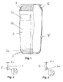
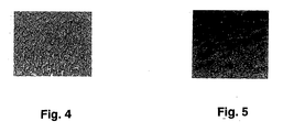
- Fig. 4 shows a photograph of the area F, namely a fine grain, Fig. 5 of the area G, which is roughly grained.
Landscapes
- Engineering & Computer Science (AREA)
- General Engineering & Computer Science (AREA)
- Mechanical Engineering (AREA)
- Fluid-Damping Devices (AREA)
- Diaphragms And Bellows (AREA)
- Vehicle Body Suspensions (AREA)
- Pipe Accessories (AREA)
- Arrangement Or Mounting Of Propulsion Units For Vehicles (AREA)
Abstract
Description
- Technisches Gebiet Die Erfindung betrifft eine Membran, umfassend einen Grundkörper, wobei der Grundkörper eine Oberfläche aufweist, wobei dem Grundkörper zumindest bereichsweise eine Struktur zugeordnet ist und wobei die Struktur Erhebungen aufweist, die mit einer maximalen Höhe von der Oberfläche abragen. Die Erfindung betrifft des Weiteren eine Luftfeder mit einer Membran.
- Membranen und Luftfedern der eingangs genannten Art sind aus dem Stand der Technik bereits bekannt. Die gattungsbildenden Luftfedern weisen im Hinblick auf ihre Qualität und Lebensdauer erhebliche Nachteile auf. Diese Nachteile werden insbesondere durch die Fertigung der Membranen bedingt.
- Bei der Herstellung von Membranen wird eine Vulkanisierung des Membranmaterials durchgeführt. Bei der Vulkanisierung kann sehr leicht Luft zwischen die beim Vulkanisieren verwendete Form und das Membranmaterial gelangen. Während des Aushärtungsprozesses kann diese Luft zu Unebenheiten auf der Oberfläche der Membran führen. Diese Unebenheiten werden insbesondere durch Blasenbildung bei Lufteinschlüssen bedingt.
- Um dem zu begegnen, bestreichen einige Hersteller die Membran vor der Vulkanisierung mit Lösungen. Diese Lösungen bestehen aus Materialien, welche die Oberfläche des Membranmaterials spröde machen. Wenn nun eine Form an die Membran angelegt wird, kann die Luft nach dieser Behandlung auf Grund der Sprödigkeit der Oberfläche leicht entweichen.
- Ein anderes Verfahren sieht vor, die Membran mit Gummipulver zu bestreuen. Hierbei ist nachteilig, dass dieses Material während der Vulkanisierung in die Oberfläche der Membran gelangt und es zu Brüchen des vulkanisierten Membranmaterials kommen kann. Hierdurch wird der Alterungsprozess einer Membran stark beschleunigt.
- Weitere Verfahren sehen vor, eine Form mit einem Oberflächenmuster zu versehen, welches Kanäle bildet, durch die die Luft aus der Form entweichen kann. Hierbei ist nachteilig, dass die Oberfläche der Membran stark und tief strukturiert wird. Diese Strukturierung beschleunigt die Bildung von Brüchen während der Verwendung der Membran. Auch hierdurch wird der Alterungsprozess einer Membran stark beschleunigt.
- Der Erfindung liegt daher die Aufgabe zu Grunde, eine Luftfeder zu schaffen, bei der ein problemloser Betrieb bei langer Lebensdauer gewährleistet ist.
- Erfindungsgemäß wird die vorangehende Aufgabe durch eine Membran mit den Merkmalen des Patentanspruchs 1 gelöst. Danach ist eine Membran dadurch gekennzeichnet, dass die Erhebungen maximal 0,1 mm von der Oberfläche abragen.
- Erfindungsgemäß ist erkannt worden, dass bei dieser Auswahl der Höhe der Erhebungen die Lebensdauer der Membran deutlich erhöht werden kann. Des Weiteren ist erkannt worden, dass die Wahl einer Strukturierung mit dieser Dimensionierung ein problemloses Entformen der Membran aus der Form nach der Vulkanisierung erlaubt. Es ist insbesondere erkannt worden, dass die Oberfläche der Membran nicht durch Blasenbildung in Folge von Lufteinschlüssen in ihrer Qualität beeinflusst wird und auch bei starker Belastung durch häufige Deformierung keine Sollbruchstellen ausbildet. Insoweit ist durch die Wahl der erfindungsgemäßen Dimensionierung eine Membran geschaffen, welche sich durch erhöhte Lebensdauer auszeichnet und insoweit eine problemlose Verwendung in Luftfedern ermöglicht.
- Folglich ist die eingangs genannte Aufgabe gelöst.
- Die Erhebungen könnten 0,05 mm von der Oberfläche des Grundkörpers abragen. Die Auswahl dieser Dimensionierung erlaubt eine besonders feine Maserung der Oberfläche der Membran. Diese Dimensionierung stellt gerade noch sicher, dass die Oberfläche nicht durch Lufteinschlüsse beeinträchtigt wird.
- Die Maserung der Struktur kann Riefen oder verzweigte, dendritartige Strukturen umfassen, die durch Täler von einander getrennt sind. Je nach der Feinheit der Maserung und der Höhe der Erhebungen - nämlich die höchsten Punkte der dendritartigen Strukturen - können die Stabilität des Grundkörpers der Membran sowie dessen Rückstellvermögen bei Deformierung eingestellt werden.
- Die Kanten der Erhebungen oder die Erhebungen selbst könnten abgerundet sein. Hierdurch ist sicher gestellt, dass keine Sollbruchstellen geschaffen werden, wenn die Membran gebeugt oder geknickt wird. Eine Erhebung, welche mit der Oberfläche einen nahezu rechten Winkel einschließt, bildet eine Risskante, welche bei Bewegung und/oder Deformierung der Membran leicht zum Einreißen neigt. Durch die Abrundung der Erhebungen in deren Basisbereich wird die Bildung von Sollbruchstellen oder Sollrissstellen wirksam verhindert. Die Abrundung im Kantenbereich bewirkt ein nahezu widerstandfreies und leichtes Abrollen der Membran an anliegenden Teilen.
- Die Oberfläche des Grundkörpers könnte vollständig von der Struktur bedeckt sein. Durch diese konkrete Ausgestaltung ist sicher gestellt, dass der gesamte Grundkörper im Hinblick auf seine Oberflächenbeschaffenheit optimiert ist. Diese Ausgestaltung erlaubt die Schaffung einer Oberfläche ganz ohne Lufteinschlüsse. Des Weiteren erlaubt diese Ausgestaltung die Fertigung einer Membran, die in nahezu allen Bereichen die gleiche Deformierbarkeits-Charakteristik und Elastitizität aufweist.
- Die Struktur könnte aus dem Material des Grundkörpers bestehen und mit diesem integral ausgebildet sein. Diese konkrete Ausgestaltung erlaubt die Verwendung eines einheitlichen Materials und erlaubt somit eine kostengünstige und schnelle Fertigung der Membran.
- Der Grundkörper könnte aus einem elastischen Material gefertigt sein. Die Verwendung eines elastischen Materials erlaubt die Verwendung der Membran als Dichtungsbalg. Der Dichtungsbalg könnte zwei Körpern zugeordnet sein, welche sich relativ zueinander bewegen. Hierbei wird der Dichtungsbalg bzw. die Membran deformiert. Die Verwendung eines elastischen Materials ist für diese Anwendung besonders vorteilhaft, da dieses ein hohes Rückstellvermögen bei Deformierung aufweist.
- Als elastisches Material könnte Gummi verwendet werden. Gummi stellt einen Werkstoff dar, der sich im Hinblick auf seine chemische Resistenz und Stabilität als besonders vorteilhaft erwiesen hat.
- Der Grundkörper könnte zylindrisch ausgebildet sein. Diese konkrete Ausgestaltung macht eine Verwendung der Membran als Tülle oder Dichtungsbalg zugänglich. Die Membran kann zylindrisch ausgebildeten Körpern wie Kolben oder Stempeln zugeordnet werden.
- Die Membran könnte Schultern aufweisen, zwischen denen die Struktur angeordnet ist. Diese Ausgestaltung eignet die Membran für die Verwendung in einer Luftfeder.
- An die Struktur im Bereich der Schultern könnten sich zweite Strukturen anschließen, die sich von der ersten Struktur unterscheiden. Diese konkrete Ausgestaltung erlaubt es, einzelne Bereiche der Membran an unterschiedliche Belastungen anzupassen. Hierdurch kann die Lebensdauer der Membran erhöht werden. In einem Bereich, der fein gemasert ist, kann die Membran äußerst weich und elastisch ausgebildet, in weiteren, grob gemaserten Bereichen, kann die Membran hart und stabil ausgestaltet sein.
- Die zweiten Strukturen könnte Erhebungen aufweisen, die maximal 0,5 mm von der Oberfläche abragen. Diese Ausgestaltung erlaubt eine problemlose Entformbarkeit der Membran in stark gewölbten Bereichen, nämlich den Schultern, und stellt zugleich einen sehr stabilen Schulterbereich sicher.
- Die eingangs genannte Aufgabe wird des Weiteren mit einer Luftfeder gemäß Patentanspruch 11 gelöst.
- Um Wiederholungen in Bezug auf die erfinderische Tätigkeit zu vermeiden, sei auf die Ausführungen zur Membran als solcher verwiesen.
- Die Verwendung einer Membran in einer Luftfeder erlaubt es, Luftfedern zu schaffen, welche sich durch eine erhöhte Lebensdauer auszeichnen. Die Luftfedern könnten in Kraftfahrzeugen, insbesondere in Achssystemen von Kraftfahrzeugen, Verwendung finden. Die Luftfeder eignet sich besonders für diese Verwendung, da Bauteile in Achssystemen häufigen Lastwechseln ausgesetzt sind, wodurch die Membran ständigen Bewegungen und Deformierungen unterworfen wird. Herkömmliche Membranen können diesen Belastungen nur eine begrenzte Zeit standhalten. Die erfindungsgemäße Membran und die erfindungsgemäße Luftfeder weisen eine deutlich höhere Lebensdauer als die gattungsbildenden Membranen und Luftfedern auf und können daher zur Schaffung von Achssystemen mit einer hohen Lebensdauer verwendet werden.
- Bei der konkreten Verwendung der Membran als Luftfederbalg könnte der mittlere Bereich des Luftfederbalgs bzw. der Membran - der Bereich zwischen den Schultern einer Luftfeder - strukturiert sein. Dieser Bereich wird besonders stark durch Deformierungen und Bewegungen der beweglichen Luftfederteile ausgebeult und damit deformiert. Die oben genannten Dimensionierungen der Struktur stellen sicher, dass der Luftfederbalg auch im Bereich zwischen den Schultern einer Luftfeder nicht ausreißt und/ oder zu Sollbruchstellen neigt. Bei den bekannten Luftfedern ist der Bereich zwischen den Schultern der Luftfeder nicht strukturiert ausgebildet, um Sollbruchstellen zu vermeiden.
- Es gibt nun verschiedene Möglichkeiten, die Lehre der vorliegenden Erfindung auf vorteilhafte Weise auszugestalten und weiterzubilden. Dazu ist einerseits auf die nachgeordneten Patentansprüche und andererseits auf die nachfolgende Erläuterung eines bevorzugten Ausführungsbeispiels der Erfindung anhand der Zeichnung zu verweisen. In Verbindung mit der Erläuterung des bevorzugten Ausführungsbeispiels der Erfindung anhand der Zeichnung werden auch im Allgemeinen bevorzugte Ausgestaltungen und Weiterbildungen der Lehre erläutert.
- In der Zeichnung zeigen
- Fig. 1
- eine Luftfeder, umfassend eine Membran mit einem Grundkörper, welcher strukturierte Oberflächen aufweist,
- Fig. 2
- eine Detailansicht des Bereichs F gemäß Fig. 1,
- Fig. 3
- eine Detailansicht des Bereichs G gemäß Fig. 1,
- Fig. 4
- eine fotografische Darstellung der Struktur des Bereichs F und
- Fig. 5
- eine fotografische Darstellung der Struktur des Bereichs G.
- Fig. 1 zeigt eine Membran, mit einem Grundkörper 1, wobei der Grundkörper 1 eine Oberfläche 2 aufweist. Dem Grundkörper 1 sind zumindest bereichsweise Strukturen 3, 3a zugeordnet, welche Erhebungen 4, 4a aufweisen. Die Erhebungen 4, 4a ragen jeweils mit einer maximalen Höhe von der Oberfläche 2 ab.
- Fig. 2 zeigt in einer Detailansicht den Bereich F gemäß Fig. 1. Die Erhebungen 4 der Struktur 3 ragen maximal 0,1 mm und vorzugsweise 0,05 mm von der Oberfläche 2 des Grundkörpers 1 ab. Die Erhebungen 4 bewegen sich folglich im Bereich d1 zwischen 0,05 und 0,1 mm. Die Kanten und Fußpunkte der Erhebungen 4 sind abgerundet. Der Krümmungsradius ist mit R bezeichnet.
- Die Struktur 3 besteht aus dem Material des Grundkörpers 1 und ist mit diesem integral ausgebildet. Der Grundkörper 1 ist aus einem elastischen Material, nämlich Gummi, gefertigt.
- Der Grundkörper 1 ist zylindrisch ausgebildet, so dass die Membran als Luftfederbalg einer Luftfeder Verwendung findet. Die Membran ist im Bereich zwischen den Schultern 5 einer Luftfeder strukturiert ausgebildet. In diesem sich länglich erstreckenden Bereich, der überwiegend tonnenförmig ausgestaltet ist, ist die Struktur 3 gemäß Fig. 2 ausgebildet.
- Fig. 3 zeigt in einer Detailansicht den Bereich G gemäß Fig. 1. Die Erhebungen 4a der Struktur 3a ragen maximal 0,5 mm von der Oberfläche 2 des Grundkörpers 1 ab. Die Erhebungen 4a bewegen sich im Bereich d2 zwischen 0,3 und 0,5 mm. Die Kanten und Fußpunkte der Erhebungen 4a sind abgerundet. Der Krümmungsradius ist mit R bezeichnet. Im Bereich der Schultern 5 ist die Struktur 3a gemäß Fig. 3 ausgebildet. Der Bereich G ist streifenförmig ausgebildet und unterscheidet sich strukturell vom Bereich F.
- Fig. 4 zeigt eine Fotografie des Bereichs F, nämlich eine feine Maserung, Fig. 5 des Bereichs G, welcher grob gemasert ist.
- Hinsichtlich weiterer vorteilhafter Ausgestaltungen und Weiterbildungen der erfindungsgemäßen Lehre wird einerseits auf den allgemeinen Teil der Beschreibung und andererseits auf die beigefügten Patentansprüche verwiesen. Abschließend sei ganz besonders hervorgehoben, dass das zuvor rein willkürlich gewählte Ausführungsbeispiel lediglich zur Erörterung der erfindungsgemäßen Lehre dient, diese jedoch nicht auf dieses Ausführungsbeispiel einschränkt.
Claims (11)
- Membran, umfassend einen Grundkörper (1), wobei der Grundkörper (1) eine Oberfläche (2) aufweist, wobei dem Grundkörper (1) zumindest bereichsweise eine Struktur (3) zugeordnet ist und wobei die Struktur (3) Erhebungen (4) aufweist, die mit einer maximalen Höhe von der Oberfläche (2) abragen, dadurch gekennzeichnet, dass die Erhebungen (4) maximal 0,1 mm von der Oberfläche (2) abragen.
- Membran nach Anspruch 1, dadurch gekennzeichnet, dass die Erhebungen (4) maximal 0,05 mm von der Oberfläche (2) des Grundkörpers (1) abragen.
- Membran nach Anspruch 1 oder 2, dadurch gekennzeichnet, dass die Kanten der Erhebungen (4) abgerundet sind.
- Membran nach einem der Ansprüche 1 bis 3, dadurch gekennzeichnet, dass die Oberfläche (2) des Grundkörpers (1) vollständig von der Struktur (3) bedeckt ist.
- Membran nach einem der Ansprüche 1 bis 4, dadurch gekennzeichnet, dass die Struktur (3) aus dem Material des Grundkörpers (1) besteht und mit diesem integral ausgebildet ist.
- Membran nach einem der Ansprüche 1 bis 5, dadurch gekennzeichnet, dass der Grundkörper (1) aus einem elastischen Material gefertigt ist.
- Membran nach einem der Ansprüche 1 bis 6, dadurch gekennzeichnet, dass der Grundkörper (1) zylindrisch ausgebildet ist.
- Membran nach einem der Ansprüche 1 bis 7, gekennzeichnet durch Schultern (5), zwischen denen die Struktur (3) angeordnet ist.
- Membran nach Anspruch 8, dadurch gekennzeichnet, dass sich an die Struktur (3) im Bereich der Schultern (5) zweite Strukturen (3a) anschließen, die sich von der ersten Struktur (3) unterscheiden.
- Membran nach Anspruch 9, dadurch gekennzeichnet, dass die zweiten Strukturen (3a) Erhebungen (4a) aufweisen, die maximal 0,5 mm von der Oberfläche (2) abragen.
- Luftfeder, umfassend eine Membran nach einem der Ansprüche 1 bis 10.
Priority Applications (1)
| Application Number | Priority Date | Filing Date | Title |
|---|---|---|---|
| PL07003465T PL1832411T3 (pl) | 2006-03-09 | 2007-02-20 | Membrana i amortyzator powietrzny |
Applications Claiming Priority (2)
| Application Number | Priority Date | Filing Date | Title |
|---|---|---|---|
| DE102006011369 | 2006-03-09 | ||
| DE102006013075A DE102006013075A1 (de) | 2006-03-09 | 2006-03-22 | Membran und Luftfeder |
Publications (3)
| Publication Number | Publication Date |
|---|---|
| EP1832411A2 true EP1832411A2 (de) | 2007-09-12 |
| EP1832411A3 EP1832411A3 (de) | 2008-09-03 |
| EP1832411B1 EP1832411B1 (de) | 2010-07-21 |
Family
ID=38042820
Family Applications (1)
| Application Number | Title | Priority Date | Filing Date |
|---|---|---|---|
| EP07003465A Active EP1832411B1 (de) | 2006-03-09 | 2007-02-20 | Membran und Luftfeder |
Country Status (4)
| Country | Link |
|---|---|
| EP (1) | EP1832411B1 (de) |
| AT (1) | ATE474713T1 (de) |
| DE (2) | DE102006013075A1 (de) |
| PL (1) | PL1832411T3 (de) |
Families Citing this family (2)
| Publication number | Priority date | Publication date | Assignee | Title |
|---|---|---|---|---|
| DE202012011829U1 (de) * | 2012-12-11 | 2013-02-26 | Continental Teves Ag & Co. Ohg | Heizmanschette für die Vulkanisation eines Schlauchrollbalges einer Luftfeder und Schlauchrollbalg für eine Luftfeder |
| DE102015202263B4 (de) * | 2015-02-09 | 2024-10-02 | Contitech Luftfedersysteme Gmbh | Wandung eines ein Fluid aufnehmenden Raumes |
Family Cites Families (6)
| Publication number | Priority date | Publication date | Assignee | Title |
|---|---|---|---|---|
| DE1891998U (de) * | 1962-10-06 | 1964-04-30 | Phoenix Gummiwerke Ag | Luftfederbalg aus gummi mit gewebeeinlagen. |
| US3435734A (en) * | 1966-07-12 | 1969-04-01 | Goodrich Co B F | Airbrake diaphragm |
| DE3318060A1 (de) * | 1983-05-18 | 1984-11-22 | Continental Gummi-Werke Ag, 3000 Hannover | Rollbalg fuer fahrzeug-fuftfederungen |
| DE3515942A1 (de) * | 1985-05-03 | 1986-11-06 | Continental Gummi-Werke Ag, 3000 Hannover | Rollbalg fuer fahrzeug-luftfederungen |
| IT1266811B1 (it) * | 1993-12-23 | 1997-01-21 | Psa Sist Antivibranti Spa | Membrana flessibile per molle ad aria, ed apparecchiatura di stampaggi |
| DE10313696B4 (de) * | 2003-03-27 | 2009-03-19 | Gkn Driveline International Gmbh | Faltenbalg |
-
2006
- 2006-03-22 DE DE102006013075A patent/DE102006013075A1/de not_active Ceased
-
2007
- 2007-02-20 DE DE502007004445T patent/DE502007004445D1/de active Active
- 2007-02-20 PL PL07003465T patent/PL1832411T3/pl unknown
- 2007-02-20 EP EP07003465A patent/EP1832411B1/de active Active
- 2007-02-20 AT AT07003465T patent/ATE474713T1/de active
Also Published As
| Publication number | Publication date |
|---|---|
| ATE474713T1 (de) | 2010-08-15 |
| PL1832411T3 (pl) | 2010-12-31 |
| DE102006013075A1 (de) | 2007-09-20 |
| EP1832411B1 (de) | 2010-07-21 |
| DE502007004445D1 (de) | 2010-09-02 |
| EP1832411A3 (de) | 2008-09-03 |
Similar Documents
| Publication | Publication Date | Title |
|---|---|---|
| DE102019134845B4 (de) | Elektrisierungseinrichtung und elektrische Staubsammelvorrichtung | |
| DE102011002065A1 (de) | Lageranordnung für eine Feder eines Fahrzeugfahrwerks | |
| DE102016003048A1 (de) | Vorrichtung und verfahren zur betätigung mechanischer schaltmittel | |
| DE102015209881A1 (de) | Vorrichtung zum Halten eines Bauteils | |
| EP1832411B1 (de) | Membran und Luftfeder | |
| DE3237834A1 (de) | Achsfeder fuer ein schienenfahrzeug | |
| EP0679125B1 (de) | Gummigefedertes schienenrad | |
| DE102015104864A1 (de) | Lagerelement für einen Stabilisator eines Fahrzeugs | |
| DE102019115009A1 (de) | Druckkopf und Verfahren zur Herstellung eines Druckkopfs | |
| DE8706688U1 (de) | Vorrichtung für die Kalibrierung von Schlauchfolienblasen | |
| DE3921936A1 (de) | Vorrichtung zum belueften von wasser | |
| DE102022200844B3 (de) | Verfahren zur Herstellung eines Dichtrings | |
| EP3224007A1 (de) | Aufnahmevorrichtung für die fixierung polymerere kfz-stossfänger | |
| DE102014106756B4 (de) | Müllgemischausbreitungsvorrichtung | |
| DE102023211803A1 (de) | Reinigungssystem für einen Lidarsensor mit einem Blickfeld | |
| DE102023119440A1 (de) | Beschichtungsvorrichtung zum Aufbringen eines viskosen Materials sowie Verfahren zum Fördern von viskosem Material auf ein Substrat | |
| EP0539798B1 (de) | Gerätefuss für Fernsprechgeräte | |
| DE102016216912A1 (de) | Verfahren zur Individualisierung eines Fahrzeugs | |
| DE2701940A1 (de) | Bauelemente fuer vakuum-rueckschlagventile | |
| EP3350054B1 (de) | Federvorrichtung zur aufnahme von querkräften und schienenfahrzeugen umfassend eine federvorrichtung | |
| Steinberger | Borderline-Kommunikation | |
| EP4591964A1 (de) | Filter mit filterelement und verfahren zur herstellung eines filterelements | |
| FR3142719A3 (fr) | Elément de garnissage et siège de véhicule | |
| DE102019006452A1 (de) | Verfahren zum Herstellen eines Schaumkörpers für einen Fahrzeugsitz sowie Schaumkörper für einen Fahrzeugsitz | |
| DE102022128603A1 (de) | Verfahren zur Herstellung einer Klebeverbindung |
Legal Events
| Date | Code | Title | Description |
|---|---|---|---|
| PUAI | Public reference made under article 153(3) epc to a published international application that has entered the european phase |
Free format text: ORIGINAL CODE: 0009012 |
|
| AK | Designated contracting states |
Kind code of ref document: A2 Designated state(s): AT BE BG CH CY CZ DE DK EE ES FI FR GB GR HU IE IS IT LI LT LU LV MC NL PL PT RO SE SI SK TR |
|
| AX | Request for extension of the european patent |
Extension state: AL BA HR MK YU |
|
| PUAL | Search report despatched |
Free format text: ORIGINAL CODE: 0009013 |
|
| AK | Designated contracting states |
Kind code of ref document: A3 Designated state(s): AT BE BG CH CY CZ DE DK EE ES FI FR GB GR HU IE IS IT LI LT LU LV MC NL PL PT RO SE SI SK TR |
|
| AX | Request for extension of the european patent |
Extension state: AL BA HR MK RS |
|
| 17P | Request for examination filed |
Effective date: 20081201 |
|
| AKX | Designation fees paid |
Designated state(s): AT BE BG CH CY CZ DE DK EE ES FI FR GB GR HU IE IS IT LI LT LU LV MC NL PL PT RO SE SI SK TR |
|
| GRAP | Despatch of communication of intention to grant a patent |
Free format text: ORIGINAL CODE: EPIDOSNIGR1 |
|
| GRAS | Grant fee paid |
Free format text: ORIGINAL CODE: EPIDOSNIGR3 |
|
| GRAA | (expected) grant |
Free format text: ORIGINAL CODE: 0009210 |
|
| AK | Designated contracting states |
Kind code of ref document: B1 Designated state(s): AT BE BG CH CY CZ DE DK EE ES FI FR GB GR HU IE IS IT LI LT LU LV MC NL PL PT RO SE SI SK TR |
|
| REG | Reference to a national code |
Ref country code: GB Ref legal event code: FG4D Free format text: NOT ENGLISH |
|
| REG | Reference to a national code |
Ref country code: CH Ref legal event code: EP |
|
| REG | Reference to a national code |
Ref country code: IE Ref legal event code: FG4D |
|
| REF | Corresponds to: |
Ref document number: 502007004445 Country of ref document: DE Date of ref document: 20100902 Kind code of ref document: P |
|
| REG | Reference to a national code |
Ref country code: SE Ref legal event code: TRGR |
|
| REG | Reference to a national code |
Ref country code: NL Ref legal event code: VDEP Effective date: 20100721 |
|
| LTIE | Lt: invalidation of european patent or patent extension |
Effective date: 20100721 |
|
| REG | Reference to a national code |
Ref country code: PL Ref legal event code: T3 |
|
| REG | Reference to a national code |
Ref country code: HU Ref legal event code: AG4A Ref document number: E008875 Country of ref document: HU |
|
| PG25 | Lapsed in a contracting state [announced via postgrant information from national office to epo] |
Ref country code: NL Free format text: LAPSE BECAUSE OF FAILURE TO SUBMIT A TRANSLATION OF THE DESCRIPTION OR TO PAY THE FEE WITHIN THE PRESCRIBED TIME-LIMIT Effective date: 20100721 Ref country code: LT Free format text: LAPSE BECAUSE OF FAILURE TO SUBMIT A TRANSLATION OF THE DESCRIPTION OR TO PAY THE FEE WITHIN THE PRESCRIBED TIME-LIMIT Effective date: 20100721 Ref country code: FI Free format text: LAPSE BECAUSE OF FAILURE TO SUBMIT A TRANSLATION OF THE DESCRIPTION OR TO PAY THE FEE WITHIN THE PRESCRIBED TIME-LIMIT Effective date: 20100721 |
|
| REG | Reference to a national code |
Ref country code: IE Ref legal event code: FD4D |
|
| PG25 | Lapsed in a contracting state [announced via postgrant information from national office to epo] |
Ref country code: PT Free format text: LAPSE BECAUSE OF FAILURE TO SUBMIT A TRANSLATION OF THE DESCRIPTION OR TO PAY THE FEE WITHIN THE PRESCRIBED TIME-LIMIT Effective date: 20101122 Ref country code: SI Free format text: LAPSE BECAUSE OF FAILURE TO SUBMIT A TRANSLATION OF THE DESCRIPTION OR TO PAY THE FEE WITHIN THE PRESCRIBED TIME-LIMIT Effective date: 20100721 Ref country code: IS Free format text: LAPSE BECAUSE OF FAILURE TO SUBMIT A TRANSLATION OF THE DESCRIPTION OR TO PAY THE FEE WITHIN THE PRESCRIBED TIME-LIMIT Effective date: 20101121 Ref country code: BG Free format text: LAPSE BECAUSE OF FAILURE TO SUBMIT A TRANSLATION OF THE DESCRIPTION OR TO PAY THE FEE WITHIN THE PRESCRIBED TIME-LIMIT Effective date: 20101021 Ref country code: CY Free format text: LAPSE BECAUSE OF FAILURE TO SUBMIT A TRANSLATION OF THE DESCRIPTION OR TO PAY THE FEE WITHIN THE PRESCRIBED TIME-LIMIT Effective date: 20100721 |
|
| PG25 | Lapsed in a contracting state [announced via postgrant information from national office to epo] |
Ref country code: GR Free format text: LAPSE BECAUSE OF FAILURE TO SUBMIT A TRANSLATION OF THE DESCRIPTION OR TO PAY THE FEE WITHIN THE PRESCRIBED TIME-LIMIT Effective date: 20101022 Ref country code: LV Free format text: LAPSE BECAUSE OF FAILURE TO SUBMIT A TRANSLATION OF THE DESCRIPTION OR TO PAY THE FEE WITHIN THE PRESCRIBED TIME-LIMIT Effective date: 20100721 |
|
| PLBI | Opposition filed |
Free format text: ORIGINAL CODE: 0009260 |
|
| PG25 | Lapsed in a contracting state [announced via postgrant information from national office to epo] |
Ref country code: IE Free format text: LAPSE BECAUSE OF FAILURE TO SUBMIT A TRANSLATION OF THE DESCRIPTION OR TO PAY THE FEE WITHIN THE PRESCRIBED TIME-LIMIT Effective date: 20100721 Ref country code: DK Free format text: LAPSE BECAUSE OF FAILURE TO SUBMIT A TRANSLATION OF THE DESCRIPTION OR TO PAY THE FEE WITHIN THE PRESCRIBED TIME-LIMIT Effective date: 20100721 |
|
| PLAB | Opposition data, opponent's data or that of the opponent's representative modified |
Free format text: ORIGINAL CODE: 0009299OPPO |
|
| PLAX | Notice of opposition and request to file observation + time limit sent |
Free format text: ORIGINAL CODE: EPIDOSNOBS2 |
|
| 26 | Opposition filed |
Opponent name: CONTINENTAL AKTIENGESELLSCHAFT Effective date: 20110421 |
|
| PG25 | Lapsed in a contracting state [announced via postgrant information from national office to epo] |
Ref country code: RO Free format text: LAPSE BECAUSE OF FAILURE TO SUBMIT A TRANSLATION OF THE DESCRIPTION OR TO PAY THE FEE WITHIN THE PRESCRIBED TIME-LIMIT Effective date: 20100721 Ref country code: SK Free format text: LAPSE BECAUSE OF FAILURE TO SUBMIT A TRANSLATION OF THE DESCRIPTION OR TO PAY THE FEE WITHIN THE PRESCRIBED TIME-LIMIT Effective date: 20100721 Ref country code: EE Free format text: LAPSE BECAUSE OF FAILURE TO SUBMIT A TRANSLATION OF THE DESCRIPTION OR TO PAY THE FEE WITHIN THE PRESCRIBED TIME-LIMIT Effective date: 20100721 Ref country code: CZ Free format text: LAPSE BECAUSE OF FAILURE TO SUBMIT A TRANSLATION OF THE DESCRIPTION OR TO PAY THE FEE WITHIN THE PRESCRIBED TIME-LIMIT Effective date: 20100721 |
|
| R26 | Opposition filed (corrected) |
Opponent name: CONTINENTAL AG Effective date: 20110421 |
|
| PG25 | Lapsed in a contracting state [announced via postgrant information from national office to epo] |
Ref country code: ES Free format text: LAPSE BECAUSE OF FAILURE TO SUBMIT A TRANSLATION OF THE DESCRIPTION OR TO PAY THE FEE WITHIN THE PRESCRIBED TIME-LIMIT Effective date: 20101101 |
|
| REG | Reference to a national code |
Ref country code: DE Ref legal event code: R026 Ref document number: 502007004445 Country of ref document: DE Effective date: 20110421 |
|
| BERE | Be: lapsed |
Owner name: CARL FREUDENBERG K.G. Effective date: 20110228 |
|
| PLBB | Reply of patent proprietor to notice(s) of opposition received |
Free format text: ORIGINAL CODE: EPIDOSNOBS3 |
|
| PG25 | Lapsed in a contracting state [announced via postgrant information from national office to epo] |
Ref country code: MC Free format text: LAPSE BECAUSE OF NON-PAYMENT OF DUE FEES Effective date: 20110228 |
|
| REG | Reference to a national code |
Ref country code: CH Ref legal event code: PL |
|
| PLAY | Examination report in opposition despatched + time limit |
Free format text: ORIGINAL CODE: EPIDOSNORE2 |
|
| PG25 | Lapsed in a contracting state [announced via postgrant information from national office to epo] |
Ref country code: CH Free format text: LAPSE BECAUSE OF NON-PAYMENT OF DUE FEES Effective date: 20110228 Ref country code: LI Free format text: LAPSE BECAUSE OF NON-PAYMENT OF DUE FEES Effective date: 20110228 |
|
| PG25 | Lapsed in a contracting state [announced via postgrant information from national office to epo] |
Ref country code: BE Free format text: LAPSE BECAUSE OF NON-PAYMENT OF DUE FEES Effective date: 20110228 |
|
| PLBC | Reply to examination report in opposition received |
Free format text: ORIGINAL CODE: EPIDOSNORE3 |
|
| REG | Reference to a national code |
Ref country code: AT Ref legal event code: MM01 Ref document number: 474713 Country of ref document: AT Kind code of ref document: T Effective date: 20120220 |
|
| PG25 | Lapsed in a contracting state [announced via postgrant information from national office to epo] |
Ref country code: LU Free format text: LAPSE BECAUSE OF NON-PAYMENT OF DUE FEES Effective date: 20110220 |
|
| PG25 | Lapsed in a contracting state [announced via postgrant information from national office to epo] |
Ref country code: AT Free format text: LAPSE BECAUSE OF NON-PAYMENT OF DUE FEES Effective date: 20120220 |
|
| PLCK | Communication despatched that opposition was rejected |
Free format text: ORIGINAL CODE: EPIDOSNREJ1 |
|
| APAH | Appeal reference modified |
Free format text: ORIGINAL CODE: EPIDOSCREFNO |
|
| APBM | Appeal reference recorded |
Free format text: ORIGINAL CODE: EPIDOSNREFNO |
|
| APBP | Date of receipt of notice of appeal recorded |
Free format text: ORIGINAL CODE: EPIDOSNNOA2O |
|
| APBQ | Date of receipt of statement of grounds of appeal recorded |
Free format text: ORIGINAL CODE: EPIDOSNNOA3O |
|
| PGFP | Annual fee paid to national office [announced via postgrant information from national office to epo] |
Ref country code: PL Payment date: 20140122 Year of fee payment: 8 Ref country code: IT Payment date: 20140218 Year of fee payment: 8 |
|
| REG | Reference to a national code |
Ref country code: DE Ref legal event code: R081 Ref document number: 502007004445 Country of ref document: DE Owner name: VIBRACOUSTIC CV AIR SPRINGS GMBH, DE Free format text: FORMER OWNER: CARL FREUDENBERG KG, 69469 WEINHEIM, DE Effective date: 20140717 |
|
| REG | Reference to a national code |
Ref country code: GB Ref legal event code: 732E Free format text: REGISTERED BETWEEN 20150305 AND 20150311 |
|
| REG | Reference to a national code |
Ref country code: FR Ref legal event code: TP Owner name: VIBRACOUSTIC CV AIRSPRINGS GMBH, DE Effective date: 20150303 |
|
| REG | Reference to a national code |
Ref country code: HU Ref legal event code: FH1C Free format text: FORMER REPRESENTATIVE(S): MESZAROSNE DONUSZ KATALIN, S.B.G & K. SZABADALMI UEGYVIVOEI IRODA, HU Representative=s name: SBGK UEGYVEDI IRODA, HU Ref country code: HU Ref legal event code: GB9C Owner name: VIBRACOUSTIC CV AIRSPRINGS GMBH, DE Free format text: FORMER OWNER(S): CARL FREUDENBERG KG, DE |
|
| PG25 | Lapsed in a contracting state [announced via postgrant information from national office to epo] |
Ref country code: IT Free format text: LAPSE BECAUSE OF NON-PAYMENT OF DUE FEES Effective date: 20150220 |
|
| REG | Reference to a national code |
Ref country code: FR Ref legal event code: PLFP Year of fee payment: 10 |
|
| PG25 | Lapsed in a contracting state [announced via postgrant information from national office to epo] |
Ref country code: PL Free format text: LAPSE BECAUSE OF NON-PAYMENT OF DUE FEES Effective date: 20150220 |
|
| PGFP | Annual fee paid to national office [announced via postgrant information from national office to epo] |
Ref country code: GB Payment date: 20160223 Year of fee payment: 10 |
|
| REG | Reference to a national code |
Ref country code: FR Ref legal event code: PLFP Year of fee payment: 11 |
|
| GBPC | Gb: european patent ceased through non-payment of renewal fee |
Effective date: 20170220 |
|
| REG | Reference to a national code |
Ref country code: FR Ref legal event code: PLFP Year of fee payment: 12 |
|
| PG25 | Lapsed in a contracting state [announced via postgrant information from national office to epo] |
Ref country code: GB Free format text: LAPSE BECAUSE OF NON-PAYMENT OF DUE FEES Effective date: 20170220 |
|
| REG | Reference to a national code |
Ref country code: DE Ref legal event code: R100 Ref document number: 502007004445 Country of ref document: DE |
|
| APBU | Appeal procedure closed |
Free format text: ORIGINAL CODE: EPIDOSNNOA9O |
|
| PLBN | Opposition rejected |
Free format text: ORIGINAL CODE: 0009273 |
|
| STAA | Information on the status of an ep patent application or granted ep patent |
Free format text: STATUS: OPPOSITION REJECTED |
|
| 27O | Opposition rejected |
Effective date: 20180725 |
|
| REG | Reference to a national code |
Ref country code: DE Ref legal event code: R082 Ref document number: 502007004445 Country of ref document: DE Representative=s name: PATENTANWAELTE OLBRICHT, BUCHHOLD, KEULERTZ PA, DE |
|
| PGFP | Annual fee paid to national office [announced via postgrant information from national office to epo] |
Ref country code: SE Payment date: 20220216 Year of fee payment: 16 Ref country code: FR Payment date: 20220216 Year of fee payment: 16 |
|
| REG | Reference to a national code |
Ref country code: SE Ref legal event code: EUG |
|
| PG25 | Lapsed in a contracting state [announced via postgrant information from national office to epo] |
Ref country code: SE Free format text: LAPSE BECAUSE OF NON-PAYMENT OF DUE FEES Effective date: 20230221 |
|
| PG25 | Lapsed in a contracting state [announced via postgrant information from national office to epo] |
Ref country code: FR Free format text: LAPSE BECAUSE OF NON-PAYMENT OF DUE FEES Effective date: 20230228 |
|
| PGFP | Annual fee paid to national office [announced via postgrant information from national office to epo] |
Ref country code: HU Payment date: 20260220 Year of fee payment: 20 |
|
| PGFP | Annual fee paid to national office [announced via postgrant information from national office to epo] |
Ref country code: DE Payment date: 20260228 Year of fee payment: 20 |
|
| PGFP | Annual fee paid to national office [announced via postgrant information from national office to epo] |
Ref country code: TR Payment date: 20260216 Year of fee payment: 20 |