EP1832417A2 - Machine de traitement avec au moins une unité d'entrainement avec au moins un régulateur d'entrainement regulé par un motéur - Google Patents
Machine de traitement avec au moins une unité d'entrainement avec au moins un régulateur d'entrainement regulé par un motéur Download PDFInfo
- Publication number
- EP1832417A2 EP1832417A2 EP07101537A EP07101537A EP1832417A2 EP 1832417 A2 EP1832417 A2 EP 1832417A2 EP 07101537 A EP07101537 A EP 07101537A EP 07101537 A EP07101537 A EP 07101537A EP 1832417 A2 EP1832417 A2 EP 1832417A2
- Authority
- EP
- European Patent Office
- Prior art keywords
- processing machine
- machine according
- drive
- sensor
- motor
- Prior art date
- Legal status (The legal status is an assumption and is not a legal conclusion. Google has not performed a legal analysis and makes no representation as to the accuracy of the status listed.)
- Granted
Links
Images
Classifications
-
- B—PERFORMING OPERATIONS; TRANSPORTING
- B41—PRINTING; LINING MACHINES; TYPEWRITERS; STAMPS
- B41F—PRINTING MACHINES OR PRESSES
- B41F33/00—Indicating, counting, warning, control or safety devices
- B41F33/04—Tripping devices or stop-motions
- B41F33/14—Automatic control of tripping devices by feelers, photoelectric devices, pneumatic devices, or other detectors
-
- B—PERFORMING OPERATIONS; TRANSPORTING
- B41—PRINTING; LINING MACHINES; TYPEWRITERS; STAMPS
- B41F—PRINTING MACHINES OR PRESSES
- B41F33/00—Indicating, counting, warning, control or safety devices
-
- B—PERFORMING OPERATIONS; TRANSPORTING
- B41—PRINTING; LINING MACHINES; TYPEWRITERS; STAMPS
- B41F—PRINTING MACHINES OR PRESSES
- B41F33/00—Indicating, counting, warning, control or safety devices
- B41F33/16—Programming systems for automatic control of sequence of operations
-
- B—PERFORMING OPERATIONS; TRANSPORTING
- B41—PRINTING; LINING MACHINES; TYPEWRITERS; STAMPS
- B41F—PRINTING MACHINES OR PRESSES
- B41F33/00—Indicating, counting, warning, control or safety devices
- B41F33/18—Web break detection
-
- G—PHYSICS
- G05—CONTROLLING; REGULATING
- G05B—CONTROL OR REGULATING SYSTEMS IN GENERAL; FUNCTIONAL ELEMENTS OF SUCH SYSTEMS; MONITORING OR TESTING ARRANGEMENTS FOR SUCH SYSTEMS OR ELEMENTS
- G05B19/00—Program-control systems
- G05B19/02—Program-control systems electric
- G05B19/04—Program control other than numerical control, i.e. in sequence controllers or logic controllers
- G05B19/048—Monitoring; Safety
-
- B—PERFORMING OPERATIONS; TRANSPORTING
- B41—PRINTING; LINING MACHINES; TYPEWRITERS; STAMPS
- B41P—INDEXING SCHEME RELATING TO PRINTING, LINING MACHINES, TYPEWRITERS, AND TO STAMPS
- B41P2213/00—Arrangements for actuating or driving printing presses; Auxiliary devices or processes
- B41P2213/70—Driving devices associated with particular installations or situations
-
- B—PERFORMING OPERATIONS; TRANSPORTING
- B41—PRINTING; LINING MACHINES; TYPEWRITERS; STAMPS
- B41P—INDEXING SCHEME RELATING TO PRINTING, LINING MACHINES, TYPEWRITERS, AND TO STAMPS
- B41P2233/00—Arrangements for the operation of printing presses
- B41P2233/20—Safety devices preventing damage
Definitions
- the invention relates to processing machines, in particular printing machines, having at least one drive unit with a drive controller regulating at least one motor according to the preamble of claim 1 or 4.
- a motor arranged in a printing machine with a rotational speed controlling control unit wherein two directed to a paper web sensors are connected to the control unit, the sensors detect a web tension of the paper web, the control unit increases the rotational speed of the motor when the web tension a falls below the permissible minimum value and reduces the rotational speed if the web tension exceeds a permissible maximum value.
- a controller for rotary printing machines wherein in the respective drive control unit of decentralized drives freely programmable function modules are implemented, which perform in cooperation with other control components decentralized control functions, which are not immediate and local drive functions.
- the function module can z. B. be connected to a temperature sensor, wherein the function module transmits the measurement signal of this sensor via a bus system to the respective drive control unit.
- an offset web-fed rotary printing press comprising a plurality of printing units
- the printing units being assigned a drive control unit, wherein two optical sensors directed onto the respective transfer cylinder guide their measuring signal respectively to the drive control unit, wherein the sensors detect a possible web break or web winder on the respective transfer cylinder, wherein the drive control unit brings the offset web-fed rotary printing press by a separation of the drives from its power supply to a standstill in a detected web break or web winder.
- the invention has for its object to provide processing machines with at least one drive unit with a controller controlling at least one motor, wherein the drive controller in a simple manner in particular to the reliability of the processing machine operating conditions is adaptable.
- the advantages that can be achieved with the invention are, in particular, that a reaction time to a sensor-detected disturbance that has occurred in the production process of the processing machine for triggering a safety-relevant device of the processing machine can be kept comparatively short. With a reduced reaction time to a fault, the machine protection is improved, which increases the reliability of the processing machine and the use of resources and / or consumables z. B. improved by a reduction of waste paper otherwise produced in a disorder.
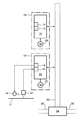
- FIG. 1 shows schematically an arrangement of drive units, each with a control unit, wherein at least one of these control units has connections for connecting a sensor and an actuator.
- the invention particularly relates to a z. Example, as a web-fed printing press or as a sheet-fed press or as a gravure printing machine trained printing machine, ie a processing a substrate in particular by printing Processing machine, said printing machines are each formed in particular as a rotary printing press.
- the printing press prints z. B. in a planographic printing process, for. B. in an offset printing process, ie in a wet offset using a dampening method or in a dry offset printing without dampening solution.
- the printing machine can z. B. be used as a newspaper printing press or as a commercial printing press.
- the printing machine is z. B. formed as a multi-section printing unit, wherein the sections of the printing system are operable individually in independent productions, each section has at least one section computer for coordinating the execution in the respective section production process.
- the section computer accordingly controls a production sequence to be executed by the respective section.
- the section computer is connected via a communication network with a plurality of sections of the printing system higher-level control unit in preferably bidirectional data connection.
- the communication network of the printing system is z. B. Ethernet-based.
- Each of the sections of the printing system has at least one machine unit, preferably a plurality of machine units.
- the machine unit or at least one of the machine units may be formed z. B. as an at least two cooperating cylinder and an inking unit having printing unit or as a feed train or as a guide system of a web-like substrate or as a comprehensive at least one catch roller railway security system or as a roll changer or as a logistics system for supplying the substrate to the printing press or as a Chill roll stand or as a dryer or as a folder.
- the printing material can be used as a material web, for. B. be designed as a paper web, or as a sheet.
- the printing system is preferably composed of several machine units, Each machine unit forms an independent module of this printing system.
- the printing system has a plurality, preferably also a plurality of similar machine units, in particular a plurality, for. B. to a printing tower stacked printing units through which a substrate to be printed is guided vertically, wherein in the printing plant several of these printing towers can be placed horizontally strung together, in which case several towers optionally with the inclusion of at least one further machine unit, z.
- Example designed as a reel changer or as a folding machine unit, form a section of the printing system.
- Modules of the printing system are manufactured individually and independently of each other, assembled and tested in their respective function; They form a closed, complex, exchangeable functional unit in the printing system.
- a functioning printing press or printing system is formed only at its place of use by joining and interconnecting several machine units and usually further, different from the machine units functional units that z. B. as a z. B. a display device having control and / or visualization unit and / or as a data server and / or as a network interface are formed, wherein the various machine units and the other functional units are preferably networked by their respective connection to the communication network of the printing system with each other.
- the operating and / or visualization unit is z. B. formed in conjunction with a control station of the printing system.
- the display device of the operating and / or visualization unit visualizes data relevant to a printing process executed or to be carried out by the printing system.
- the network interface of the printing system can enable communication between machine units and functional units connected to the communications network of the printing system with an external computer, ie, outside and separate from the printing system via a local area network (LAN) and / or via a globally operating network (Internet) / or coordinate.
- LAN local area network
- Internet globally operating network
- Each machine unit preferably has several components.
- a component may, for. B. be designed as a controllable component, for. B. as a drive unit.
- the drive unit closes z. B. a position-controlled or a variable speed or a torque-controlled electric motor, which z. B. a role recording a reel changer or one or more cylinders z. B. a printing unit or a folder or one or more rollers z. B. an inking unit and / or a dampening unit or draw rollers in a web guide system drives.
- a z. B. as a printing unit or as a folding machine unit formed preferably several drive units are provided.
- a plurality of drive units together with their respective control unit are arranged decentrally in the printing press or in the printing system.
- Each drive unit has a motor-regulating drive controller, wherein the operation of this motor, ie the axis driven by this motor, with regard to further z. B. in the same or in another machine unit or preferably at least provided in the same section to coordinate driven axes.
- This coordination of different, coordinated in their respective operation driven axles preferably takes a designated as motion control unit, said decentralized z.
- each drive unit may be associated with such a control unit or wherein a central control unit is provided for a plurality of drive units controlled by it.
- the at least one drive unit controlling control unit has z. B.
- a logic processor which allows fast signal processing for controlling the executed by the drive unit or the drive units movement sequence.
- the control unit controlling at least one drive unit or multiple drive units can be combined in one unit with a drive controller of one of the drive units, so that preferably the drive controller has the logic processor.
- the executed by the drive unit or the drive units movement allows a transport speed of the printing material of z. 16 m / s or more if the Substrate is web-shaped, or of 18,000 sheets per hour or more, if this is arc-shaped, wherein the substrate is transported at this particular transport speed through the printing press or printing system and thereby processed into a printed product.
- z. B provided in connection with one or more machine units at least one device that detects an occurred in the production process of the printing machine disturbance.
- Such an operational disturbance can z.
- the an operational failure recognizing device has z. B. at least one sensor that detects this disorder and generates a signal indicating this disturbance.
- a sensor may, for. B. be designed as an optical measuring device or as a temperature sensor.
- the optical measuring device is z. B.
- a web break detecting device can also z. B. use at least one ultrasonic sensor or other a distance or a passage detecting sensor.
- the device that detects an operational disturbance directs the signal indicating a malfunction in the printing process to a sequential control system provided in or on one of the machine units, wherein this sequence control z. B. is designed as a programmable logic controller (PLC) with preferably a plurality of signal inputs and signal outputs. After the sequence control has evaluated the signal indicating the fault, the sequencer actuates due to its programming by a remote from her Output signal z. B. a belonging to a safety device of the printing press actuator to respond to the detected fault and / or initiate a measure to remedy and / or to mitigate an effect of the fault, the safety-relevant device z. B.
- PLC programmable logic controller
- the action triggered by the sequence control and / or the safety-relevant device usually includes, however, also acting on one or more drive units of the printing system to this z. B. controlled to bring to a halt, or at least to slow down. It has been shown that in practice the reaction time from the sensory recognition of a disturbance in the production process to the initiation of a minimizing or avoiding measure is in need of improvement. In particular, too low a data processing speed in the sequence control and / or too complex signal paths leading via a plurality of interfaces are considered to be the cause of an excessively long reaction time.
- At least one control unit controlling at least one drive unit with at least one signal input for the connection of a sensor for detecting an operational disturbance, so that at least this one drive unit can react directly and directly to the recognized operational disturbance.
- the recoverable time gain in the reaction time can z. B. in the range between 30% and 80%.
- the at least one of the drive units controlling control unit which receives the signal indicating a fault, z. B. also have at least one signal output, at the z. B. a safety-relevant device, eg. As a beater blade or a take-up or a transfer gate for the substrate, to the respective control can be connected.
- the printing unit drive units 01; 02, z. B. in a printing unit in each case at least one cylinder and / or at least one roller driving drive units 01; 02, are connected to a communication network of the printing system, wherein the drive units 01; 02 connecting part of the communication network z. B. is designed as a local drive bus 03.
- the z. B. the standard Sercos III or Profinet corresponding local drive bus 03 is connected to a motion control 04 in data connection, wherein the motion control 04 by the connected to the local drive bus 03 drive units 01; 02 driven axles z. B. coordinated in their relative angular position to each other.
- the task of the motion control 04 is therefore primarily to synchronize the motion sequence of different axes with each other in time, this task is due to the high speed with which the individual movements are executed only by one or more logic processors with a very fast data processing solvable.
- the motion control 04 is in turn with an equally z.
- B. the standard Sercos III or Profinet corresponding higher-level drive bus 06 in data connection, wherein the parent drive bus 06 is part of the arranged in the printing system communication network, the parent drive bus 06 in turn to a the production process in a section coordinating section computer (not shown) and this in turn via another part of the communication network z.
- B. may be connected to a control station of the printing system.
- the communication network arranged in the printing system can therefore be designed as a cascaded communication system with a plurality of hierarchically structured control levels.
- control levels be consistent, uniform and thus not subdivided into sub-communication network provided.
- the drive units 01 connected to the local drive bus 03; 02 each have at least one motor 07; 08 regulating drive controller 09; 11 on.
- a this operational failure detection device is provided, said this operational failure recognizing device z. B. has at least one sensor 12 which detects this disorder and generates a signal indicating this disturbance.
- This sensor 12 is z. B. formed as a light barrier or as a reflex sensor and directed in its direction of action on the substrate 17. The signal generated by the sensor 12 during the detection of a fault occurring in the production process of the printing press is fed to one of the drive controllers 09, which receives this signal indicative of a fault at a signal input 13.
- the drive unit 01 can react directly and directly to the detected disturbance.
- This reaction may include that the drive controller 09 of this drive unit 01 slows down the movement sequence of the motor 07 of this drive unit 01 and / or brings it to a standstill in a controlled manner.
- the reaction of the drive controller 09 can provide that the drive controller 09 controls a safety-related device of the printing press via a signal output 14, wherein the safety-relevant device z. B. has an actuator 16, wherein the actuator 16 is formed as a controllable, preferably electrically controllable actuator 16, which converts a signal of the drive controller 09 into mechanical work, ie preferably in a movement.
- the actuator 16 operates z. B. acting on the substrate 17 or a Ausschlagel the take-up material 17 take-up or the substrate 17 from its transport path through the printing press or
- the other provided in the printing press or printing unit drive units 01; 02 can each have a drive controller 09; 11 having at least one signal input 13 for receiving a signal generated by a sensor 12 and optionally a signal output 14 for controlling an actuator 16 of a safety-relevant device.
- the signal input 13 and / or the signal output 14 of the drive controller 09; 11 are each parameterized in particular and thus adapted to different sensors 12 and / or actuators 16, whereby the respective drive controller 09; 11 is easily adaptable to its respective operating environment and / or its respective operating conditions.
- a received at a drive controller 09 signal from a sensor 12 of this drive controller 09 is also forwarded to other connected to the local drive bus 03 drive controller 11 so that the motors of the other associated drive units 01; 02 can respond to the signal of the sensor 12 indicating an operational fault.
- the signal indicative of an operational failure of the sensor 12 which has been recorded by one of the controller 09, z. B. via the motion control 04 and the parent drive bus 06 to further drive units 01; 02, to control the motors there as a function of the detected fault and / or at least one to the respective drive controller 09; 11 of the other drive units 01; 02 connected actuator 16 to control.
- An operational malfunction detected by a sensor 12 can be arranged in drive units 01; 02 trigger different, overarching reactions.
- the motion control 04 in one of the drive controller 09; 11 of the drive units 01; 02 integrated trained. It can be provided that a plurality of drive units 01; 02 coordinating motion control 04 coordinated by her drive units 01; 02 on one of a failure detected by a sensor 12 can react differently by providing these drive units 01; 02 slows down differently and / or brings to a standstill with different reaction times. Depending on the task of the respective drive units 01; 02, their respective response to the operational disturbance detected by a sensor 12 disposed in the respective array may be uniform or nonuniform.
Landscapes
- Physics & Mathematics (AREA)
- General Physics & Mathematics (AREA)
- Engineering & Computer Science (AREA)
- Automation & Control Theory (AREA)
- Inking, Control Or Cleaning Of Printing Machines (AREA)
- Control Of Electric Motors In General (AREA)
- Feedback Control In General (AREA)
Applications Claiming Priority (1)
| Application Number | Priority Date | Filing Date | Title |
|---|---|---|---|
| DE200610011201 DE102006011201B4 (de) | 2006-03-10 | 2006-03-10 | Druckmaschine mit mehreren Antriebseinheiten |
Publications (3)
| Publication Number | Publication Date |
|---|---|
| EP1832417A2 true EP1832417A2 (fr) | 2007-09-12 |
| EP1832417A3 EP1832417A3 (fr) | 2011-08-03 |
| EP1832417B1 EP1832417B1 (fr) | 2013-10-09 |
Family
ID=38229052
Family Applications (1)
| Application Number | Title | Priority Date | Filing Date |
|---|---|---|---|
| EP20070101537 Not-in-force EP1832417B1 (fr) | 2006-03-10 | 2007-02-01 | Machine de traitement avec au moins une unité d'entrainement avec au moins un régulateur d'entrainement regulé par un motéur |
Country Status (2)
| Country | Link |
|---|---|
| EP (1) | EP1832417B1 (fr) |
| DE (1) | DE102006011201B4 (fr) |
Cited By (2)
| Publication number | Priority date | Publication date | Assignee | Title |
|---|---|---|---|---|
| CN103287093A (zh) * | 2013-05-30 | 2013-09-11 | 常熟市众望经纬编织造有限公司 | 竹炭纤维毛毯用平网印花机控制系统 |
| EP3699701A1 (fr) * | 2019-02-25 | 2020-08-26 | Siemens Aktiengesellschaft | Procédé et dispositif de détermination ou de prédiction d'une position d'une déchirure de la bande, programme informatique et installation industrielle |
Families Citing this family (1)
| Publication number | Priority date | Publication date | Assignee | Title |
|---|---|---|---|---|
| EP3699356A1 (fr) * | 2019-02-25 | 2020-08-26 | Siemens Aktiengesellschaft | Procédé et dispositif de détection d'une déchirure d'un bande de fibre, installation industrielle ainsi que produit programme informatique |
Citations (6)
| Publication number | Priority date | Publication date | Assignee | Title |
|---|---|---|---|---|
| JPS62278037A (ja) | 1986-05-28 | 1987-12-02 | Mitsubishi Heavy Ind Ltd | 輪転印刷機の紙通し装置 |
| US4966074A (en) | 1989-02-13 | 1990-10-30 | Aldrich Jr Wesley C | Web wrap detection system for an offset web printing press |
| DE10129889A1 (de) | 2000-07-14 | 2002-01-24 | Heidelberger Druckmasch Ag | Verfahren und Vorrichtung zur Störungserfassung beim Transport einer Bahn |
| US6456222B1 (en) | 2001-05-25 | 2002-09-24 | Siemens Aktiengesellschaft | Sensor signal converter for machine tools and production machines, and also robots |
| EP1375140A2 (fr) | 2002-06-19 | 2004-01-02 | Koenig & Bauer Aktiengesellschaft | Commande pour machines d'impression rotatives |
| DE10317570B3 (de) | 2003-04-16 | 2004-09-16 | Koenig & Bauer Ag | Antriebsvorrichtung eines Aggregates einer Druckmaschine |
Family Cites Families (10)
| Publication number | Priority date | Publication date | Assignee | Title |
|---|---|---|---|---|
| DE3125722A1 (de) * | 1981-06-30 | 1983-01-13 | Siemens AG, 1000 Berlin und 8000 München | Steuerungssystem, insbesondere fuer automatische fertigungsanlagen |
| DE3730625A1 (de) * | 1987-09-11 | 1989-03-23 | Wifag Maschf | Positioniersystem der qualitaetsfuehrungsfunktionen in rotationsdruckmaschinen |
| US6891838B1 (en) * | 1998-06-22 | 2005-05-10 | Statsignal Ipc, Llc | System and method for monitoring and controlling residential devices |
| DE19908230A1 (de) * | 1999-02-25 | 2000-08-31 | Heidelberger Druckmasch Ag | Vorrichtung zur Überwachung von sicherheitsrelevanten Vorgängen an Maschinen |
| DE20000919U1 (de) * | 2000-01-20 | 2000-03-09 | MAN Roland Druckmaschinen AG, 63075 Offenbach | Überwachungseinrichtung für eine Druckmaschine |
| DE20004400U1 (de) * | 2000-03-09 | 2001-07-19 | Cooper Power Tools GmbH & Co., 73463 Westhausen | Betriebsnetzwerksystem |
| DE10052046B4 (de) * | 2000-10-20 | 2010-02-04 | Koenig & Bauer Aktiengesellschaft | Steuerung für Rotationsdruckmaschinen |
| DE10113261C2 (de) * | 2001-03-16 | 2003-07-10 | Siemens Ag | Synchrones, getaktetes Kommunikationssystem mit dezentralen Ein-/Ausgabe-Baugruppen und Verfahren zur Einbindung dezentraler Ein-/Ausgabe-Baugruppen in ein solches System |
| EP1388769A1 (fr) * | 2002-08-05 | 2004-02-11 | Peter Renner | Système pour automatiser, surveiller, commander et pour la détection de valeurs de mesure pour des procédés techniques |
| DE102004022703A1 (de) * | 2004-05-05 | 2006-01-05 | Koenig & Bauer Ag | Vorrichtung zur Erkennung von Lagerschäden mit Warnsignalausgabe |
-
2006
- 2006-03-10 DE DE200610011201 patent/DE102006011201B4/de not_active Expired - Fee Related
-
2007
- 2007-02-01 EP EP20070101537 patent/EP1832417B1/fr not_active Not-in-force
Patent Citations (6)
| Publication number | Priority date | Publication date | Assignee | Title |
|---|---|---|---|---|
| JPS62278037A (ja) | 1986-05-28 | 1987-12-02 | Mitsubishi Heavy Ind Ltd | 輪転印刷機の紙通し装置 |
| US4966074A (en) | 1989-02-13 | 1990-10-30 | Aldrich Jr Wesley C | Web wrap detection system for an offset web printing press |
| DE10129889A1 (de) | 2000-07-14 | 2002-01-24 | Heidelberger Druckmasch Ag | Verfahren und Vorrichtung zur Störungserfassung beim Transport einer Bahn |
| US6456222B1 (en) | 2001-05-25 | 2002-09-24 | Siemens Aktiengesellschaft | Sensor signal converter for machine tools and production machines, and also robots |
| EP1375140A2 (fr) | 2002-06-19 | 2004-01-02 | Koenig & Bauer Aktiengesellschaft | Commande pour machines d'impression rotatives |
| DE10317570B3 (de) | 2003-04-16 | 2004-09-16 | Koenig & Bauer Ag | Antriebsvorrichtung eines Aggregates einer Druckmaschine |
Cited By (4)
| Publication number | Priority date | Publication date | Assignee | Title |
|---|---|---|---|---|
| CN103287093A (zh) * | 2013-05-30 | 2013-09-11 | 常熟市众望经纬编织造有限公司 | 竹炭纤维毛毯用平网印花机控制系统 |
| EP3699701A1 (fr) * | 2019-02-25 | 2020-08-26 | Siemens Aktiengesellschaft | Procédé et dispositif de détermination ou de prédiction d'une position d'une déchirure de la bande, programme informatique et installation industrielle |
| WO2020173880A1 (fr) * | 2019-02-25 | 2020-09-03 | Siemens Aktiengesellschaft | Procédé et dispositif pour déterminer ou prédire une position d'une rupture de bande, programme informatique et installation industrielle |
| US12085927B2 (en) | 2019-02-25 | 2024-09-10 | Siemens Aktiengesellschaft | Computer program product, industrial installation, method and apparatus for determining or predicting a position of a web break |
Also Published As
| Publication number | Publication date |
|---|---|
| DE102006011201B4 (de) | 2011-12-01 |
| DE102006011201A1 (de) | 2007-09-13 |
| EP1832417B1 (fr) | 2013-10-09 |
| EP1832417A3 (fr) | 2011-08-03 |
Similar Documents
| Publication | Publication Date | Title |
|---|---|---|
| EP0976674B1 (fr) | Dispositif de réglage de la tension d'une bande | |
| DE10135773B4 (de) | Verfahren und Vorrichtung zum Steuern von Antrieben einer Druckmaschine | |
| EP1505023A2 (fr) | Méthode et dispositif pour controler la tension d'une bande et le répérage de coup d'une imprimante rotative | |
| EP1505024A2 (fr) | Méthode et dispositif pour contrôler le répérage de découpe d'une imprimante rotative | |
| EP3959078A1 (fr) | Machine de traitement de feuille et procédé pour inspecter une feuille | |
| EP2147789B1 (fr) | Procédé destiné au fonctionnement d'une machine d'impression sur bandes | |
| EP0976556A1 (fr) | Système d'entretien et diagnostic pour une machine d'impression | |
| EP1275499B1 (fr) | Dispositif d'entrainement d'un appareil de pliage d'une machine à imprimer rotative | |
| EP1832417B1 (fr) | Machine de traitement avec au moins une unité d'entrainement avec au moins un régulateur d'entrainement regulé par un motéur | |
| EP1252018B1 (fr) | Procede pour reguler la tension d'une bande dans une rotative | |
| WO2014202254A1 (fr) | Machine d'impression équipée d'un système à jet d'encre et procédé d'impression d'une surface cible | |
| EP1619026B1 (fr) | Machine d'impression avec un dispositif de déclenchement d'un appareil de capture d'image et/ou d'illumination | |
| EP1745925B2 (fr) | Dispositif de contrôle de registre | |
| DE10027471A1 (de) | Verfahren zur Regelung einer Bahnspannung in einer Rotationsdruckmaschine | |
| DE102005054975B4 (de) | Registerregelung bei einer Druckmaschine | |
| EP2098369B1 (fr) | Procédé de fonctionnement d'une imprimante comprenant plusieurs unités d'impression | |
| EP0759360B1 (fr) | Procédé de commande d'un dispositif d'impression | |
| EP2108511B1 (fr) | Réglage d'un registre de coupe | |
| EP0747215B1 (fr) | Dispositif de commande pour une machine à imprimer | |
| DE102018220970B4 (de) | Verfahren zum Einrichten einer Bogendruckmaschine unter wechselnder Verwendung von Makulaturbogen und unbedruckten Bogen | |
| DE102008000522B4 (de) | Vorrichtung zur Erkennung einer in ihrem Lauf gestörten Materialbahn | |
| DE102013211251B4 (de) | Druckmaschine mit mehreren gemeinsam einen Bedruckstoff bedruckenden Druckwerken | |
| DE102008000526A1 (de) | Verfahren zum Betreiben einer mehrere Druckeinheiten aufweisenden Druckmaschine | |
| DE4214707A1 (de) | Steuerung fuer einen druckmaschinen-antriebsmotor | |
| EP1391322B1 (fr) | Unité de travail pour un processus traversé par des produits imprimés |
Legal Events
| Date | Code | Title | Description |
|---|---|---|---|
| PUAI | Public reference made under article 153(3) epc to a published international application that has entered the european phase |
Free format text: ORIGINAL CODE: 0009012 |
|
| AK | Designated contracting states |
Kind code of ref document: A2 Designated state(s): AT BE BG CH CY CZ DE DK EE ES FI FR GB GR HU IE IS IT LI LT LU LV MC NL PL PT RO SE SI SK TR |
|
| AX | Request for extension of the european patent |
Extension state: AL BA HR MK YU |
|
| RIC1 | Information provided on ipc code assigned before grant |
Ipc: B41F 33/00 20060101ALI20110523BHEP Ipc: G05B 19/00 20060101ALI20110523BHEP Ipc: B41F 33/18 20060101ALI20110523BHEP Ipc: B41F 33/14 20060101ALI20110523BHEP Ipc: B41F 13/004 20060101AFI20070717BHEP Ipc: B41F 33/16 20060101ALI20110523BHEP |
|
| PUAL | Search report despatched |
Free format text: ORIGINAL CODE: 0009013 |
|
| AK | Designated contracting states |
Kind code of ref document: A3 Designated state(s): AT BE BG CH CY CZ DE DK EE ES FI FR GB GR HU IE IS IT LI LT LU LV MC NL PL PT RO SE SI SK TR |
|
| AX | Request for extension of the european patent |
Extension state: AL BA HR MK RS |
|
| 17P | Request for examination filed |
Effective date: 20110708 |
|
| AKX | Designation fees paid |
Designated state(s): AT BE BG CH CY CZ DE DK EE ES FI FR GB GR HU IE IS IT LI LT LU LV MC NL PL PT RO SE SI SK TR |
|
| GRAP | Despatch of communication of intention to grant a patent |
Free format text: ORIGINAL CODE: EPIDOSNIGR1 |
|
| INTG | Intention to grant announced |
Effective date: 20130612 |
|
| GRAS | Grant fee paid |
Free format text: ORIGINAL CODE: EPIDOSNIGR3 |
|
| GRAA | (expected) grant |
Free format text: ORIGINAL CODE: 0009210 |
|
| AK | Designated contracting states |
Kind code of ref document: B1 Designated state(s): AT BE BG CH CY CZ DE DK EE ES FI FR GB GR HU IE IS IT LI LT LU LV MC NL PL PT RO SE SI SK TR |
|
| REG | Reference to a national code |
Ref country code: GB Ref legal event code: FG4D Free format text: NOT ENGLISH |
|
| REG | Reference to a national code |
Ref country code: AT Ref legal event code: REF Ref document number: 635379 Country of ref document: AT Kind code of ref document: T Effective date: 20131015 Ref country code: CH Ref legal event code: EP |
|
| REG | Reference to a national code |
Ref country code: IE Ref legal event code: FG4D Free format text: LANGUAGE OF EP DOCUMENT: GERMAN |
|
| REG | Reference to a national code |
Ref country code: DE Ref legal event code: R096 Ref document number: 502007012363 Country of ref document: DE Effective date: 20131205 |
|
| REG | Reference to a national code |
Ref country code: NL Ref legal event code: VDEP Effective date: 20131009 |
|
| PG25 | Lapsed in a contracting state [announced via postgrant information from national office to epo] |
Ref country code: SI Free format text: LAPSE BECAUSE OF FAILURE TO SUBMIT A TRANSLATION OF THE DESCRIPTION OR TO PAY THE FEE WITHIN THE PRESCRIBED TIME-LIMIT Effective date: 20131009 |
|
| REG | Reference to a national code |
Ref country code: LT Ref legal event code: MG4D |
|
| PG25 | Lapsed in a contracting state [announced via postgrant information from national office to epo] |
Ref country code: NL Free format text: LAPSE BECAUSE OF FAILURE TO SUBMIT A TRANSLATION OF THE DESCRIPTION OR TO PAY THE FEE WITHIN THE PRESCRIBED TIME-LIMIT Effective date: 20131009 Ref country code: FI Free format text: LAPSE BECAUSE OF FAILURE TO SUBMIT A TRANSLATION OF THE DESCRIPTION OR TO PAY THE FEE WITHIN THE PRESCRIBED TIME-LIMIT Effective date: 20131009 Ref country code: LT Free format text: LAPSE BECAUSE OF FAILURE TO SUBMIT A TRANSLATION OF THE DESCRIPTION OR TO PAY THE FEE WITHIN THE PRESCRIBED TIME-LIMIT Effective date: 20131009 Ref country code: IS Free format text: LAPSE BECAUSE OF FAILURE TO SUBMIT A TRANSLATION OF THE DESCRIPTION OR TO PAY THE FEE WITHIN THE PRESCRIBED TIME-LIMIT Effective date: 20140209 Ref country code: SE Free format text: LAPSE BECAUSE OF FAILURE TO SUBMIT A TRANSLATION OF THE DESCRIPTION OR TO PAY THE FEE WITHIN THE PRESCRIBED TIME-LIMIT Effective date: 20131009 |
|
| PG25 | Lapsed in a contracting state [announced via postgrant information from national office to epo] |
Ref country code: ES Free format text: LAPSE BECAUSE OF FAILURE TO SUBMIT A TRANSLATION OF THE DESCRIPTION OR TO PAY THE FEE WITHIN THE PRESCRIBED TIME-LIMIT Effective date: 20131009 Ref country code: CY Free format text: LAPSE BECAUSE OF FAILURE TO SUBMIT A TRANSLATION OF THE DESCRIPTION OR TO PAY THE FEE WITHIN THE PRESCRIBED TIME-LIMIT Effective date: 20131009 Ref country code: PL Free format text: LAPSE BECAUSE OF FAILURE TO SUBMIT A TRANSLATION OF THE DESCRIPTION OR TO PAY THE FEE WITHIN THE PRESCRIBED TIME-LIMIT Effective date: 20131009 Ref country code: LV Free format text: LAPSE BECAUSE OF FAILURE TO SUBMIT A TRANSLATION OF THE DESCRIPTION OR TO PAY THE FEE WITHIN THE PRESCRIBED TIME-LIMIT Effective date: 20131009 |
|
| PG25 | Lapsed in a contracting state [announced via postgrant information from national office to epo] |
Ref country code: PT Free format text: LAPSE BECAUSE OF FAILURE TO SUBMIT A TRANSLATION OF THE DESCRIPTION OR TO PAY THE FEE WITHIN THE PRESCRIBED TIME-LIMIT Effective date: 20140210 |
|
| REG | Reference to a national code |
Ref country code: DE Ref legal event code: R097 Ref document number: 502007012363 Country of ref document: DE |
|
| PG25 | Lapsed in a contracting state [announced via postgrant information from national office to epo] |
Ref country code: EE Free format text: LAPSE BECAUSE OF FAILURE TO SUBMIT A TRANSLATION OF THE DESCRIPTION OR TO PAY THE FEE WITHIN THE PRESCRIBED TIME-LIMIT Effective date: 20131009 |
|
| PLBE | No opposition filed within time limit |
Free format text: ORIGINAL CODE: 0009261 |
|
| STAA | Information on the status of an ep patent application or granted ep patent |
Free format text: STATUS: NO OPPOSITION FILED WITHIN TIME LIMIT |
|
| PG25 | Lapsed in a contracting state [announced via postgrant information from national office to epo] |
Ref country code: CZ Free format text: LAPSE BECAUSE OF FAILURE TO SUBMIT A TRANSLATION OF THE DESCRIPTION OR TO PAY THE FEE WITHIN THE PRESCRIBED TIME-LIMIT Effective date: 20131009 Ref country code: RO Free format text: LAPSE BECAUSE OF FAILURE TO SUBMIT A TRANSLATION OF THE DESCRIPTION OR TO PAY THE FEE WITHIN THE PRESCRIBED TIME-LIMIT Effective date: 20131009 Ref country code: SK Free format text: LAPSE BECAUSE OF FAILURE TO SUBMIT A TRANSLATION OF THE DESCRIPTION OR TO PAY THE FEE WITHIN THE PRESCRIBED TIME-LIMIT Effective date: 20131009 |
|
| BERE | Be: lapsed |
Owner name: KOENIG & BAUER A.G. Effective date: 20140228 |
|
| 26N | No opposition filed |
Effective date: 20140710 |
|
| PG25 | Lapsed in a contracting state [announced via postgrant information from national office to epo] |
Ref country code: DK Free format text: LAPSE BECAUSE OF FAILURE TO SUBMIT A TRANSLATION OF THE DESCRIPTION OR TO PAY THE FEE WITHIN THE PRESCRIBED TIME-LIMIT Effective date: 20131009 Ref country code: LU Free format text: LAPSE BECAUSE OF FAILURE TO SUBMIT A TRANSLATION OF THE DESCRIPTION OR TO PAY THE FEE WITHIN THE PRESCRIBED TIME-LIMIT Effective date: 20140201 Ref country code: MC Free format text: LAPSE BECAUSE OF FAILURE TO SUBMIT A TRANSLATION OF THE DESCRIPTION OR TO PAY THE FEE WITHIN THE PRESCRIBED TIME-LIMIT Effective date: 20131009 |
|
| REG | Reference to a national code |
Ref country code: DE Ref legal event code: R097 Ref document number: 502007012363 Country of ref document: DE Effective date: 20140710 |
|
| REG | Reference to a national code |
Ref country code: IE Ref legal event code: MM4A |
|
| PG25 | Lapsed in a contracting state [announced via postgrant information from national office to epo] |
Ref country code: BE Free format text: LAPSE BECAUSE OF NON-PAYMENT OF DUE FEES Effective date: 20140228 Ref country code: IE Free format text: LAPSE BECAUSE OF NON-PAYMENT OF DUE FEES Effective date: 20140201 |
|
| REG | Reference to a national code |
Ref country code: FR Ref legal event code: PLFP Year of fee payment: 9 |
|
| REG | Reference to a national code |
Ref country code: AT Ref legal event code: MM01 Ref document number: 635379 Country of ref document: AT Kind code of ref document: T Effective date: 20140201 |
|
| PGFP | Annual fee paid to national office [announced via postgrant information from national office to epo] |
Ref country code: DE Payment date: 20150318 Year of fee payment: 9 Ref country code: CH Payment date: 20150220 Year of fee payment: 9 Ref country code: IT Payment date: 20150221 Year of fee payment: 9 |
|
| PG25 | Lapsed in a contracting state [announced via postgrant information from national office to epo] |
Ref country code: AT Free format text: LAPSE BECAUSE OF NON-PAYMENT OF DUE FEES Effective date: 20140201 |
|
| PGFP | Annual fee paid to national office [announced via postgrant information from national office to epo] |
Ref country code: GB Payment date: 20150220 Year of fee payment: 9 Ref country code: FR Payment date: 20150223 Year of fee payment: 9 |
|
| REG | Reference to a national code |
Ref country code: DE Ref legal event code: R081 Ref document number: 502007012363 Country of ref document: DE Owner name: KOENIG & BAUER AG, DE Free format text: FORMER OWNER: KOENIG & BAUER AKTIENGESELLSCHAFT, 97080 WUERZBURG, DE |
|
| PG25 | Lapsed in a contracting state [announced via postgrant information from national office to epo] |
Ref country code: BG Free format text: LAPSE BECAUSE OF FAILURE TO SUBMIT A TRANSLATION OF THE DESCRIPTION OR TO PAY THE FEE WITHIN THE PRESCRIBED TIME-LIMIT Effective date: 20131009 |
|
| PG25 | Lapsed in a contracting state [announced via postgrant information from national office to epo] |
Ref country code: GR Free format text: LAPSE BECAUSE OF FAILURE TO SUBMIT A TRANSLATION OF THE DESCRIPTION OR TO PAY THE FEE WITHIN THE PRESCRIBED TIME-LIMIT Effective date: 20140110 |
|
| PG25 | Lapsed in a contracting state [announced via postgrant information from national office to epo] |
Ref country code: HU Free format text: LAPSE BECAUSE OF FAILURE TO SUBMIT A TRANSLATION OF THE DESCRIPTION OR TO PAY THE FEE WITHIN THE PRESCRIBED TIME-LIMIT; INVALID AB INITIO Effective date: 20070201 Ref country code: TR Free format text: LAPSE BECAUSE OF FAILURE TO SUBMIT A TRANSLATION OF THE DESCRIPTION OR TO PAY THE FEE WITHIN THE PRESCRIBED TIME-LIMIT Effective date: 20131009 |
|
| REG | Reference to a national code |
Ref country code: DE Ref legal event code: R119 Ref document number: 502007012363 Country of ref document: DE |
|
| REG | Reference to a national code |
Ref country code: CH Ref legal event code: PL |
|
| GBPC | Gb: european patent ceased through non-payment of renewal fee |
Effective date: 20160201 |
|
| PG25 | Lapsed in a contracting state [announced via postgrant information from national office to epo] |
Ref country code: LI Free format text: LAPSE BECAUSE OF NON-PAYMENT OF DUE FEES Effective date: 20160229 Ref country code: CH Free format text: LAPSE BECAUSE OF NON-PAYMENT OF DUE FEES Effective date: 20160229 |
|
| REG | Reference to a national code |
Ref country code: FR Ref legal event code: ST Effective date: 20161028 |
|
| PG25 | Lapsed in a contracting state [announced via postgrant information from national office to epo] |
Ref country code: IT Free format text: LAPSE BECAUSE OF NON-PAYMENT OF DUE FEES Effective date: 20160201 |
|
| PG25 | Lapsed in a contracting state [announced via postgrant information from national office to epo] |
Ref country code: DE Free format text: LAPSE BECAUSE OF NON-PAYMENT OF DUE FEES Effective date: 20160901 Ref country code: FR Free format text: LAPSE BECAUSE OF NON-PAYMENT OF DUE FEES Effective date: 20160229 Ref country code: GB Free format text: LAPSE BECAUSE OF NON-PAYMENT OF DUE FEES Effective date: 20160201 |