EP1832460A1 - Verzweigtes schaltbares elektromechanisches Getriebe und dessen Steuerung - Google Patents
Verzweigtes schaltbares elektromechanisches Getriebe und dessen Steuerung Download PDFInfo
- Publication number
- EP1832460A1 EP1832460A1 EP06300214A EP06300214A EP1832460A1 EP 1832460 A1 EP1832460 A1 EP 1832460A1 EP 06300214 A EP06300214 A EP 06300214A EP 06300214 A EP06300214 A EP 06300214A EP 1832460 A1 EP1832460 A1 EP 1832460A1
- Authority
- EP
- European Patent Office
- Prior art keywords
- shaft
- machine
- mode
- gear
- motor
- Prior art date
- Legal status (The legal status is an assumption and is not a legal conclusion. Google has not performed a legal analysis and makes no representation as to the accuracy of the status listed.)
- Granted
Links
Images



Classifications
-
- B—PERFORMING OPERATIONS; TRANSPORTING
- B60—VEHICLES IN GENERAL
- B60W—CONJOINT CONTROL OF VEHICLE SUB-UNITS OF DIFFERENT TYPE OR DIFFERENT FUNCTION; CONTROL SYSTEMS SPECIALLY ADAPTED FOR HYBRID VEHICLES; ROAD VEHICLE DRIVE CONTROL SYSTEMS FOR PURPOSES NOT RELATED TO THE CONTROL OF A PARTICULAR SUB-UNIT
- B60W20/00—Control systems specially adapted for hybrid vehicles
-
- B—PERFORMING OPERATIONS; TRANSPORTING
- B60—VEHICLES IN GENERAL
- B60K—ARRANGEMENT OR MOUNTING OF PROPULSION UNITS OR OF TRANSMISSIONS IN VEHICLES; ARRANGEMENT OR MOUNTING OF PLURAL DIVERSE PRIME-MOVERS IN VEHICLES; AUXILIARY DRIVES FOR VEHICLES; INSTRUMENTATION OR DASHBOARDS FOR VEHICLES; ARRANGEMENTS IN CONNECTION WITH COOLING, AIR INTAKE, GAS EXHAUST OR FUEL SUPPLY OF PROPULSION UNITS IN VEHICLES
- B60K6/00—Arrangement or mounting of plural diverse prime-movers for mutual or common propulsion, e.g. hybrid propulsion systems comprising electric motors and internal combustion engines
- B60K6/20—Arrangement or mounting of plural diverse prime-movers for mutual or common propulsion, e.g. hybrid propulsion systems comprising electric motors and internal combustion engines the prime-movers consisting of electric motors and internal combustion engines, e.g. HEVs
- B60K6/22—Arrangement or mounting of plural diverse prime-movers for mutual or common propulsion, e.g. hybrid propulsion systems comprising electric motors and internal combustion engines the prime-movers consisting of electric motors and internal combustion engines, e.g. HEVs characterised by apparatus, components or means specially adapted for HEVs
- B60K6/36—Arrangement or mounting of plural diverse prime-movers for mutual or common propulsion, e.g. hybrid propulsion systems comprising electric motors and internal combustion engines the prime-movers consisting of electric motors and internal combustion engines, e.g. HEVs characterised by apparatus, components or means specially adapted for HEVs characterised by the transmission gearings
- B60K6/365—Arrangement or mounting of plural diverse prime-movers for mutual or common propulsion, e.g. hybrid propulsion systems comprising electric motors and internal combustion engines the prime-movers consisting of electric motors and internal combustion engines, e.g. HEVs characterised by apparatus, components or means specially adapted for HEVs characterised by the transmission gearings with the gears having orbital motion
-
- B—PERFORMING OPERATIONS; TRANSPORTING
- B60—VEHICLES IN GENERAL
- B60K—ARRANGEMENT OR MOUNTING OF PROPULSION UNITS OR OF TRANSMISSIONS IN VEHICLES; ARRANGEMENT OR MOUNTING OF PLURAL DIVERSE PRIME-MOVERS IN VEHICLES; AUXILIARY DRIVES FOR VEHICLES; INSTRUMENTATION OR DASHBOARDS FOR VEHICLES; ARRANGEMENTS IN CONNECTION WITH COOLING, AIR INTAKE, GAS EXHAUST OR FUEL SUPPLY OF PROPULSION UNITS IN VEHICLES
- B60K6/00—Arrangement or mounting of plural diverse prime-movers for mutual or common propulsion, e.g. hybrid propulsion systems comprising electric motors and internal combustion engines
- B60K6/20—Arrangement or mounting of plural diverse prime-movers for mutual or common propulsion, e.g. hybrid propulsion systems comprising electric motors and internal combustion engines the prime-movers consisting of electric motors and internal combustion engines, e.g. HEVs
- B60K6/22—Arrangement or mounting of plural diverse prime-movers for mutual or common propulsion, e.g. hybrid propulsion systems comprising electric motors and internal combustion engines the prime-movers consisting of electric motors and internal combustion engines, e.g. HEVs characterised by apparatus, components or means specially adapted for HEVs
- B60K6/38—Arrangement or mounting of plural diverse prime-movers for mutual or common propulsion, e.g. hybrid propulsion systems comprising electric motors and internal combustion engines the prime-movers consisting of electric motors and internal combustion engines, e.g. HEVs characterised by apparatus, components or means specially adapted for HEVs characterised by the driveline clutches
- B60K6/387—Actuated clutches, i.e. clutches engaged or disengaged by electric, hydraulic or mechanical actuating means
-
- B—PERFORMING OPERATIONS; TRANSPORTING
- B60—VEHICLES IN GENERAL
- B60K—ARRANGEMENT OR MOUNTING OF PROPULSION UNITS OR OF TRANSMISSIONS IN VEHICLES; ARRANGEMENT OR MOUNTING OF PLURAL DIVERSE PRIME-MOVERS IN VEHICLES; AUXILIARY DRIVES FOR VEHICLES; INSTRUMENTATION OR DASHBOARDS FOR VEHICLES; ARRANGEMENTS IN CONNECTION WITH COOLING, AIR INTAKE, GAS EXHAUST OR FUEL SUPPLY OF PROPULSION UNITS IN VEHICLES
- B60K6/00—Arrangement or mounting of plural diverse prime-movers for mutual or common propulsion, e.g. hybrid propulsion systems comprising electric motors and internal combustion engines
- B60K6/20—Arrangement or mounting of plural diverse prime-movers for mutual or common propulsion, e.g. hybrid propulsion systems comprising electric motors and internal combustion engines the prime-movers consisting of electric motors and internal combustion engines, e.g. HEVs
- B60K6/42—Arrangement or mounting of plural diverse prime-movers for mutual or common propulsion, e.g. hybrid propulsion systems comprising electric motors and internal combustion engines the prime-movers consisting of electric motors and internal combustion engines, e.g. HEVs characterised by the architecture of the hybrid electric vehicle
- B60K6/44—Series-parallel type
- B60K6/445—Differential gearing distribution type
-
- B—PERFORMING OPERATIONS; TRANSPORTING
- B60—VEHICLES IN GENERAL
- B60L—PROPULSION OF ELECTRICALLY-PROPELLED VEHICLES; SUPPLYING ELECTRIC POWER FOR AUXILIARY EQUIPMENT OF ELECTRICALLY-PROPELLED VEHICLES; ELECTRODYNAMIC BRAKE SYSTEMS FOR VEHICLES IN GENERAL; MAGNETIC SUSPENSION OR LEVITATION FOR VEHICLES; MONITORING OPERATING VARIABLES OF ELECTRICALLY-PROPELLED VEHICLES; ELECTRIC SAFETY DEVICES FOR ELECTRICALLY-PROPELLED VEHICLES
- B60L15/00—Methods, circuits, or devices for controlling the traction-motor speed of electrically-propelled vehicles
- B60L15/20—Methods, circuits, or devices for controlling the traction-motor speed of electrically-propelled vehicles for control of the vehicle or its driving motor to achieve a desired performance, e.g. speed, torque, programmed variation of speed
- B60L15/2045—Methods, circuits, or devices for controlling the traction-motor speed of electrically-propelled vehicles for control of the vehicle or its driving motor to achieve a desired performance, e.g. speed, torque, programmed variation of speed for optimising the use of energy
-
- B—PERFORMING OPERATIONS; TRANSPORTING
- B60—VEHICLES IN GENERAL
- B60L—PROPULSION OF ELECTRICALLY-PROPELLED VEHICLES; SUPPLYING ELECTRIC POWER FOR AUXILIARY EQUIPMENT OF ELECTRICALLY-PROPELLED VEHICLES; ELECTRODYNAMIC BRAKE SYSTEMS FOR VEHICLES IN GENERAL; MAGNETIC SUSPENSION OR LEVITATION FOR VEHICLES; MONITORING OPERATING VARIABLES OF ELECTRICALLY-PROPELLED VEHICLES; ELECTRIC SAFETY DEVICES FOR ELECTRICALLY-PROPELLED VEHICLES
- B60L15/00—Methods, circuits, or devices for controlling the traction-motor speed of electrically-propelled vehicles
- B60L15/20—Methods, circuits, or devices for controlling the traction-motor speed of electrically-propelled vehicles for control of the vehicle or its driving motor to achieve a desired performance, e.g. speed, torque, programmed variation of speed
- B60L15/2054—Methods, circuits, or devices for controlling the traction-motor speed of electrically-propelled vehicles for control of the vehicle or its driving motor to achieve a desired performance, e.g. speed, torque, programmed variation of speed by controlling transmissions or clutches
-
- B—PERFORMING OPERATIONS; TRANSPORTING
- B60—VEHICLES IN GENERAL
- B60W—CONJOINT CONTROL OF VEHICLE SUB-UNITS OF DIFFERENT TYPE OR DIFFERENT FUNCTION; CONTROL SYSTEMS SPECIALLY ADAPTED FOR HYBRID VEHICLES; ROAD VEHICLE DRIVE CONTROL SYSTEMS FOR PURPOSES NOT RELATED TO THE CONTROL OF A PARTICULAR SUB-UNIT
- B60W10/00—Conjoint control of vehicle sub-units of different type or different function
- B60W10/02—Conjoint control of vehicle sub-units of different type or different function including control of driveline clutches
-
- B—PERFORMING OPERATIONS; TRANSPORTING
- B60—VEHICLES IN GENERAL
- B60W—CONJOINT CONTROL OF VEHICLE SUB-UNITS OF DIFFERENT TYPE OR DIFFERENT FUNCTION; CONTROL SYSTEMS SPECIALLY ADAPTED FOR HYBRID VEHICLES; ROAD VEHICLE DRIVE CONTROL SYSTEMS FOR PURPOSES NOT RELATED TO THE CONTROL OF A PARTICULAR SUB-UNIT
- B60W10/00—Conjoint control of vehicle sub-units of different type or different function
- B60W10/04—Conjoint control of vehicle sub-units of different type or different function including control of propulsion units
- B60W10/08—Conjoint control of vehicle sub-units of different type or different function including control of propulsion units including control of electric propulsion units, e.g. motors or generators
-
- B—PERFORMING OPERATIONS; TRANSPORTING
- B60—VEHICLES IN GENERAL
- B60W—CONJOINT CONTROL OF VEHICLE SUB-UNITS OF DIFFERENT TYPE OR DIFFERENT FUNCTION; CONTROL SYSTEMS SPECIALLY ADAPTED FOR HYBRID VEHICLES; ROAD VEHICLE DRIVE CONTROL SYSTEMS FOR PURPOSES NOT RELATED TO THE CONTROL OF A PARTICULAR SUB-UNIT
- B60W30/00—Purposes of road vehicle drive control systems not related to the control of a particular sub-unit, e.g. of systems using conjoint control of vehicle sub-units
- B60W30/18—Propelling the vehicle
- B60W30/19—Improvement of gear change, e.g. by synchronisation or smoothing gear shift
-
- F—MECHANICAL ENGINEERING; LIGHTING; HEATING; WEAPONS; BLASTING
- F16—ENGINEERING ELEMENTS AND UNITS; GENERAL MEASURES FOR PRODUCING AND MAINTAINING EFFECTIVE FUNCTIONING OF MACHINES OR INSTALLATIONS; THERMAL INSULATION IN GENERAL
- F16H—GEARING
- F16H3/00—Toothed gearings for conveying rotary motion with variable gear ratio or for reversing rotary motion
- F16H3/44—Toothed gearings for conveying rotary motion with variable gear ratio or for reversing rotary motion using gears having orbital motion
- F16H3/72—Toothed gearings for conveying rotary motion with variable gear ratio or for reversing rotary motion using gears having orbital motion with a secondary drive, e.g. regulating motor, in order to vary speed continuously
- F16H3/727—Toothed gearings for conveying rotary motion with variable gear ratio or for reversing rotary motion using gears having orbital motion with a secondary drive, e.g. regulating motor, in order to vary speed continuously with at least two dynamo electric machines for creating an electric power path inside the gearing, e.g. using generator and motor for a variable power torque path
-
- B—PERFORMING OPERATIONS; TRANSPORTING
- B60—VEHICLES IN GENERAL
- B60K—ARRANGEMENT OR MOUNTING OF PROPULSION UNITS OR OF TRANSMISSIONS IN VEHICLES; ARRANGEMENT OR MOUNTING OF PLURAL DIVERSE PRIME-MOVERS IN VEHICLES; AUXILIARY DRIVES FOR VEHICLES; INSTRUMENTATION OR DASHBOARDS FOR VEHICLES; ARRANGEMENTS IN CONNECTION WITH COOLING, AIR INTAKE, GAS EXHAUST OR FUEL SUPPLY OF PROPULSION UNITS IN VEHICLES
- B60K6/00—Arrangement or mounting of plural diverse prime-movers for mutual or common propulsion, e.g. hybrid propulsion systems comprising electric motors and internal combustion engines
- B60K6/20—Arrangement or mounting of plural diverse prime-movers for mutual or common propulsion, e.g. hybrid propulsion systems comprising electric motors and internal combustion engines the prime-movers consisting of electric motors and internal combustion engines, e.g. HEVs
- B60K6/22—Arrangement or mounting of plural diverse prime-movers for mutual or common propulsion, e.g. hybrid propulsion systems comprising electric motors and internal combustion engines the prime-movers consisting of electric motors and internal combustion engines, e.g. HEVs characterised by apparatus, components or means specially adapted for HEVs
- B60K6/34—Arrangement or mounting of plural diverse prime-movers for mutual or common propulsion, e.g. hybrid propulsion systems comprising electric motors and internal combustion engines the prime-movers consisting of electric motors and internal combustion engines, e.g. HEVs characterised by apparatus, components or means specially adapted for HEVs characterised by the absence of energy storing means
-
- B—PERFORMING OPERATIONS; TRANSPORTING
- B60—VEHICLES IN GENERAL
- B60L—PROPULSION OF ELECTRICALLY-PROPELLED VEHICLES; SUPPLYING ELECTRIC POWER FOR AUXILIARY EQUIPMENT OF ELECTRICALLY-PROPELLED VEHICLES; ELECTRODYNAMIC BRAKE SYSTEMS FOR VEHICLES IN GENERAL; MAGNETIC SUSPENSION OR LEVITATION FOR VEHICLES; MONITORING OPERATING VARIABLES OF ELECTRICALLY-PROPELLED VEHICLES; ELECTRIC SAFETY DEVICES FOR ELECTRICALLY-PROPELLED VEHICLES
- B60L2200/00—Type of vehicles
- B60L2200/26—Rail vehicles
-
- B—PERFORMING OPERATIONS; TRANSPORTING
- B60—VEHICLES IN GENERAL
- B60L—PROPULSION OF ELECTRICALLY-PROPELLED VEHICLES; SUPPLYING ELECTRIC POWER FOR AUXILIARY EQUIPMENT OF ELECTRICALLY-PROPELLED VEHICLES; ELECTRODYNAMIC BRAKE SYSTEMS FOR VEHICLES IN GENERAL; MAGNETIC SUSPENSION OR LEVITATION FOR VEHICLES; MONITORING OPERATING VARIABLES OF ELECTRICALLY-PROPELLED VEHICLES; ELECTRIC SAFETY DEVICES FOR ELECTRICALLY-PROPELLED VEHICLES
- B60L2240/00—Control parameters of input or output; Target parameters
- B60L2240/40—Drive Train control parameters
- B60L2240/42—Drive Train control parameters related to electric machines
- B60L2240/421—Speed
-
- B—PERFORMING OPERATIONS; TRANSPORTING
- B60—VEHICLES IN GENERAL
- B60L—PROPULSION OF ELECTRICALLY-PROPELLED VEHICLES; SUPPLYING ELECTRIC POWER FOR AUXILIARY EQUIPMENT OF ELECTRICALLY-PROPELLED VEHICLES; ELECTRODYNAMIC BRAKE SYSTEMS FOR VEHICLES IN GENERAL; MAGNETIC SUSPENSION OR LEVITATION FOR VEHICLES; MONITORING OPERATING VARIABLES OF ELECTRICALLY-PROPELLED VEHICLES; ELECTRIC SAFETY DEVICES FOR ELECTRICALLY-PROPELLED VEHICLES
- B60L2240/00—Control parameters of input or output; Target parameters
- B60L2240/40—Drive Train control parameters
- B60L2240/48—Drive Train control parameters related to transmissions
- B60L2240/486—Operating parameters
-
- F—MECHANICAL ENGINEERING; LIGHTING; HEATING; WEAPONS; BLASTING
- F16—ENGINEERING ELEMENTS AND UNITS; GENERAL MEASURES FOR PRODUCING AND MAINTAINING EFFECTIVE FUNCTIONING OF MACHINES OR INSTALLATIONS; THERMAL INSULATION IN GENERAL
- F16H—GEARING
- F16H37/00—Combinations of mechanical gearings, not provided for in groups F16H1/00 - F16H35/00
- F16H37/02—Combinations of mechanical gearings, not provided for in groups F16H1/00 - F16H35/00 comprising essentially only toothed or friction gearings
- F16H37/06—Combinations of mechanical gearings, not provided for in groups F16H1/00 - F16H35/00 comprising essentially only toothed or friction gearings with a plurality of driving or driven shafts; with arrangements for dividing torque between two or more intermediate shafts
- F16H37/08—Combinations of mechanical gearings, not provided for in groups F16H1/00 - F16H35/00 comprising essentially only toothed or friction gearings with a plurality of driving or driven shafts; with arrangements for dividing torque between two or more intermediate shafts with differential gearing
- F16H37/0833—Combinations of mechanical gearings, not provided for in groups F16H1/00 - F16H35/00 comprising essentially only toothed or friction gearings with a plurality of driving or driven shafts; with arrangements for dividing torque between two or more intermediate shafts with differential gearing with arrangements for dividing torque between two or more intermediate shafts, i.e. with two or more internal power paths
- F16H37/084—Combinations of mechanical gearings, not provided for in groups F16H1/00 - F16H35/00 comprising essentially only toothed or friction gearings with a plurality of driving or driven shafts; with arrangements for dividing torque between two or more intermediate shafts with differential gearing with arrangements for dividing torque between two or more intermediate shafts, i.e. with two or more internal power paths at least one power path being a continuously variable transmission, i.e. CVT
- F16H2037/0866—Power-split transmissions with distributing differentials, with the output of the CVT connected or connectable to the output shaft
-
- F—MECHANICAL ENGINEERING; LIGHTING; HEATING; WEAPONS; BLASTING
- F16—ENGINEERING ELEMENTS AND UNITS; GENERAL MEASURES FOR PRODUCING AND MAINTAINING EFFECTIVE FUNCTIONING OF MACHINES OR INSTALLATIONS; THERMAL INSULATION IN GENERAL
- F16H—GEARING
- F16H37/00—Combinations of mechanical gearings, not provided for in groups F16H1/00 - F16H35/00
- F16H37/02—Combinations of mechanical gearings, not provided for in groups F16H1/00 - F16H35/00 comprising essentially only toothed or friction gearings
- F16H37/06—Combinations of mechanical gearings, not provided for in groups F16H1/00 - F16H35/00 comprising essentially only toothed or friction gearings with a plurality of driving or driven shafts; with arrangements for dividing torque between two or more intermediate shafts
- F16H37/08—Combinations of mechanical gearings, not provided for in groups F16H1/00 - F16H35/00 comprising essentially only toothed or friction gearings with a plurality of driving or driven shafts; with arrangements for dividing torque between two or more intermediate shafts with differential gearing
- F16H37/0833—Combinations of mechanical gearings, not provided for in groups F16H1/00 - F16H35/00 comprising essentially only toothed or friction gearings with a plurality of driving or driven shafts; with arrangements for dividing torque between two or more intermediate shafts with differential gearing with arrangements for dividing torque between two or more intermediate shafts, i.e. with two or more internal power paths
- F16H37/084—Combinations of mechanical gearings, not provided for in groups F16H1/00 - F16H35/00 comprising essentially only toothed or friction gearings with a plurality of driving or driven shafts; with arrangements for dividing torque between two or more intermediate shafts with differential gearing with arrangements for dividing torque between two or more intermediate shafts, i.e. with two or more internal power paths at least one power path being a continuously variable transmission, i.e. CVT
- F16H2037/088—Power-split transmissions with summing differentials, with the input of the CVT connected or connectable to the input shaft
-
- F—MECHANICAL ENGINEERING; LIGHTING; HEATING; WEAPONS; BLASTING
- F16—ENGINEERING ELEMENTS AND UNITS; GENERAL MEASURES FOR PRODUCING AND MAINTAINING EFFECTIVE FUNCTIONING OF MACHINES OR INSTALLATIONS; THERMAL INSULATION IN GENERAL
- F16H—GEARING
- F16H37/00—Combinations of mechanical gearings, not provided for in groups F16H1/00 - F16H35/00
- F16H37/02—Combinations of mechanical gearings, not provided for in groups F16H1/00 - F16H35/00 comprising essentially only toothed or friction gearings
- F16H37/06—Combinations of mechanical gearings, not provided for in groups F16H1/00 - F16H35/00 comprising essentially only toothed or friction gearings with a plurality of driving or driven shafts; with arrangements for dividing torque between two or more intermediate shafts
- F16H37/08—Combinations of mechanical gearings, not provided for in groups F16H1/00 - F16H35/00 comprising essentially only toothed or friction gearings with a plurality of driving or driven shafts; with arrangements for dividing torque between two or more intermediate shafts with differential gearing
- F16H37/10—Combinations of mechanical gearings, not provided for in groups F16H1/00 - F16H35/00 comprising essentially only toothed or friction gearings with a plurality of driving or driven shafts; with arrangements for dividing torque between two or more intermediate shafts with differential gearing at both ends of intermediate shafts
- F16H2037/102—Combinations of mechanical gearings, not provided for in groups F16H1/00 - F16H35/00 comprising essentially only toothed or friction gearings with a plurality of driving or driven shafts; with arrangements for dividing torque between two or more intermediate shafts with differential gearing at both ends of intermediate shafts the input or output shaft of the transmission is connected or connectable to two or more differentials
-
- F—MECHANICAL ENGINEERING; LIGHTING; HEATING; WEAPONS; BLASTING
- F16—ENGINEERING ELEMENTS AND UNITS; GENERAL MEASURES FOR PRODUCING AND MAINTAINING EFFECTIVE FUNCTIONING OF MACHINES OR INSTALLATIONS; THERMAL INSULATION IN GENERAL
- F16H—GEARING
- F16H37/00—Combinations of mechanical gearings, not provided for in groups F16H1/00 - F16H35/00
- F16H37/02—Combinations of mechanical gearings, not provided for in groups F16H1/00 - F16H35/00 comprising essentially only toothed or friction gearings
- F16H37/06—Combinations of mechanical gearings, not provided for in groups F16H1/00 - F16H35/00 comprising essentially only toothed or friction gearings with a plurality of driving or driven shafts; with arrangements for dividing torque between two or more intermediate shafts
- F16H37/08—Combinations of mechanical gearings, not provided for in groups F16H1/00 - F16H35/00 comprising essentially only toothed or friction gearings with a plurality of driving or driven shafts; with arrangements for dividing torque between two or more intermediate shafts with differential gearing
- F16H37/10—Combinations of mechanical gearings, not provided for in groups F16H1/00 - F16H35/00 comprising essentially only toothed or friction gearings with a plurality of driving or driven shafts; with arrangements for dividing torque between two or more intermediate shafts with differential gearing at both ends of intermediate shafts
- F16H2037/105—Combinations of mechanical gearings, not provided for in groups F16H1/00 - F16H35/00 comprising essentially only toothed or friction gearings with a plurality of driving or driven shafts; with arrangements for dividing torque between two or more intermediate shafts with differential gearing at both ends of intermediate shafts characterised by number of modes or ranges, e.g. for compound gearing
- F16H2037/107—Combinations of mechanical gearings, not provided for in groups F16H1/00 - F16H35/00 comprising essentially only toothed or friction gearings with a plurality of driving or driven shafts; with arrangements for dividing torque between two or more intermediate shafts with differential gearing at both ends of intermediate shafts characterised by number of modes or ranges, e.g. for compound gearing with switching means to provide three variator modes or ranges
-
- F—MECHANICAL ENGINEERING; LIGHTING; HEATING; WEAPONS; BLASTING
- F16—ENGINEERING ELEMENTS AND UNITS; GENERAL MEASURES FOR PRODUCING AND MAINTAINING EFFECTIVE FUNCTIONING OF MACHINES OR INSTALLATIONS; THERMAL INSULATION IN GENERAL
- F16H—GEARING
- F16H3/00—Toothed gearings for conveying rotary motion with variable gear ratio or for reversing rotary motion
- F16H3/44—Toothed gearings for conveying rotary motion with variable gear ratio or for reversing rotary motion using gears having orbital motion
- F16H3/72—Toothed gearings for conveying rotary motion with variable gear ratio or for reversing rotary motion using gears having orbital motion with a secondary drive, e.g. regulating motor, in order to vary speed continuously
- F16H3/727—Toothed gearings for conveying rotary motion with variable gear ratio or for reversing rotary motion using gears having orbital motion with a secondary drive, e.g. regulating motor, in order to vary speed continuously with at least two dynamo electric machines for creating an electric power path inside the gearing, e.g. using generator and motor for a variable power torque path
- F16H3/728—Toothed gearings for conveying rotary motion with variable gear ratio or for reversing rotary motion using gears having orbital motion with a secondary drive, e.g. regulating motor, in order to vary speed continuously with at least two dynamo electric machines for creating an electric power path inside the gearing, e.g. using generator and motor for a variable power torque path with means to change ratio in the mechanical gearing
-
- Y—GENERAL TAGGING OF NEW TECHNOLOGICAL DEVELOPMENTS; GENERAL TAGGING OF CROSS-SECTIONAL TECHNOLOGIES SPANNING OVER SEVERAL SECTIONS OF THE IPC; TECHNICAL SUBJECTS COVERED BY FORMER USPC CROSS-REFERENCE ART COLLECTIONS [XRACs] AND DIGESTS
- Y02—TECHNOLOGIES OR APPLICATIONS FOR MITIGATION OR ADAPTATION AGAINST CLIMATE CHANGE
- Y02T—CLIMATE CHANGE MITIGATION TECHNOLOGIES RELATED TO TRANSPORTATION
- Y02T10/00—Road transport of goods or passengers
- Y02T10/60—Other road transportation technologies with climate change mitigation effect
- Y02T10/62—Hybrid vehicles
-
- Y—GENERAL TAGGING OF NEW TECHNOLOGICAL DEVELOPMENTS; GENERAL TAGGING OF CROSS-SECTIONAL TECHNOLOGIES SPANNING OVER SEVERAL SECTIONS OF THE IPC; TECHNICAL SUBJECTS COVERED BY FORMER USPC CROSS-REFERENCE ART COLLECTIONS [XRACs] AND DIGESTS
- Y02—TECHNOLOGIES OR APPLICATIONS FOR MITIGATION OR ADAPTATION AGAINST CLIMATE CHANGE
- Y02T—CLIMATE CHANGE MITIGATION TECHNOLOGIES RELATED TO TRANSPORTATION
- Y02T10/00—Road transport of goods or passengers
- Y02T10/60—Other road transportation technologies with climate change mitigation effect
- Y02T10/64—Electric machine technologies in electromobility
-
- Y—GENERAL TAGGING OF NEW TECHNOLOGICAL DEVELOPMENTS; GENERAL TAGGING OF CROSS-SECTIONAL TECHNOLOGIES SPANNING OVER SEVERAL SECTIONS OF THE IPC; TECHNICAL SUBJECTS COVERED BY FORMER USPC CROSS-REFERENCE ART COLLECTIONS [XRACs] AND DIGESTS
- Y02—TECHNOLOGIES OR APPLICATIONS FOR MITIGATION OR ADAPTATION AGAINST CLIMATE CHANGE
- Y02T—CLIMATE CHANGE MITIGATION TECHNOLOGIES RELATED TO TRANSPORTATION
- Y02T10/00—Road transport of goods or passengers
- Y02T10/60—Other road transportation technologies with climate change mitigation effect
- Y02T10/72—Electric energy management in electromobility
Definitions
- the present invention relates to a power transmission device between a shaft of a heat engine and a wheel shaft of a vehicle.
- the object of the invention is to eliminate breaks or erasures of torque at the wheel during transmission ratio changes.
- the present invention finds a particularly advantageous application in the field of motor vehicles, but it could also be implemented in trains, boats or motorcycles.
- Power transmission devices are known between a motor shaft and a wheel shaft used in hybrid vehicles. Such devices are described in the application FR-A-2832357 . These transmission devices generally comprise a heat engine, and a pair of electrical machines. The motor shaft, the shaft of the wheels and the shafts of the machines are connected to each other by means of a mechanical assembly. This mechanical assembly is generally formed of one or more planetary gear trains. The two machines are interconnected by means of a connecting device comprising in particular an electric bus. These machines behave as engine or generator depending on the mechanical and electrical energy they receive respectively on their shaft and on their terminals.
- a power supplied by the heat engine can be either transmitted directly to the wheel shaft via the mechanical assembly, or derived in an electric chain comprising the motors and the connecting device.
- the power derived in the electric chain is transmitted to the wheel shaft so as to adjust the torque applied to the shaft, while adjusting the torque and the speed of the engine to an operating point where the consumption of this engine is minimal .
- a storage system is connected to the electric bus.
- This storage system can take the form of a battery, a super capacitor or an inertia machine. Part of the derived power can then be recovered and stored in this storage system.
- the storage battery allows additional degrees of system operation.
- the two machines can simultaneously operate as a motor in an acceleration mode.
- the two machines operate simultaneously as a generator, so as to store a large amount of energy.
- the present invention consists of an improvement of the transmission device described in the application FR-A-2832357 .
- the shaft of one of the machines can be coupled to the wheel shaft of the vehicle. More specifically, in this transmission device, a shaft of one of the machines can be connected either to the wheel shaft in a first mode of operation, or to an element of the mechanical assembly in a second mode of operation.
- Each operating mode corresponds to a range of transmission ratios. The first mode corresponds to short transmission ratios, while the second mode corresponds to long transmission ratios.
- the electrical machines used are thus smaller in size than in a transmission device having only one operating mode.
- the shaft of one of the machines in a first mode of operation, is connected to one element of one of the planetary gear trains while the shaft of the other machine is connected to the wheel shaft.
- the shafts of the two machines are each connected to an element of one of the planetary gear trains.
- a shaft of one of the machines is connected to the motor shaft, while the shaft of the other machine is connected to an element of one of the planetary gear trains.
- the mechanical assembly is formed of two planetary gear trains connected to each other by their planet carrier.
- the shaft of one of the machines is connected either to the shaft of the engine or to a ring of one of the planetary gear trains.
- the shaft of the other machine is connected either to the wheel shaft of the vehicle or to a sun gear of the other epicyclic gear.
- the power transmitted by the electric chain is zero in order to more easily manage the continuity of the torque to the wheel.
- Figure 1 shows a schematic representation of a device 1 transmission of power according to the invention. This device 1 ensures a transmission of power between a shaft 2 of a thermal engine 3 and a shaft 4 of wheels 5.
- This transmission device 1 comprises a first electrical machine 6 and a second electrical machine 7 interconnected via a device 8 for electrical connection.
- a mechanical assembly 9 interconnects the shaft 4 of wheels 5, the shaft 2 of the motor 3, a shaft 10 of the first machine 6 and a shaft 11 of the second machine 7.
- This mechanical assembly 9 comprises at least two trains epicyclic. These two planetary gear trains each comprise three elements that mesh with each other. These three elements are a crown, a satellite gate and a sun gear. These two planetary gear trains are interconnected so as to have four degrees of freedom, one for each tree.
- the planetary gear trains comprise more than three elements.
- each train could have a crown with external teeth that would mesh with a fourth element.
- each train would have several planet carriers.
- the planetary gear trains are interconnected via gear shafts and pinions. In these embodiments, the gears mesh with elements of the epicyclic gear trains.
- the shaft 2 of the motor 3 is connected to a first element 24 of one of the trains of the assembly 9.
- the shaft 4 of the wheels 5 is connected to a second element 25 of one of the trains of the assembly 9.
- the shaft 11 of the second machine 7 is connected either to the shaft 2 of the motor 3 or to a third element 26 of one of the trains of the assembly 9.
- the shaft 10 of the first machine 6 is connected either to the shaft 4 of the wheels 5, or to a fourth element 27 of one of the trains of the assembly 9.
- the first, the second, the third, and the fourth element 24 -27 are four distinct elements from each other.
- the connecting device 8 comprises a first inverter 12 associated with the first machine 6 and a second inverter 13 associated with the second machine 7.
- the connecting device 8 also comprises a DC voltage bus 14 which connects the two inverters 12 and 13.
- This bus 14 comprises a first connection 14.1 and a second connection 14.2. More specifically, phases 15 of the first machine 6 are connected to the inverter 12 which is itself connected to the bus 14 via two wire links 16 and 17. Phases 18 of the second machine 7 are connected to the second inverter 13 which is itself connected to the bus 14 via two wire links 19 and 20.
- a power supplied by the shaft 2 of the motor 3 can be transmitted directly to the shaft 4 of wheels 5 by means of a mechanical chain formed by the assembly 9.
- a part of this power can also be derived by an electrical chain which comprises the two machines 6 and 7 and the connecting device 8.
- the machines 6 and 7 behave either in motor or in generator. In the configuration of the device 1 shown, no storage system is connected to the bus 14. When one of the machines operates as a generator, the other machine thus operates as a motor.
- the associated inverter 12 or 13 transforms a DC voltage signal observable on the bus 14 into alternating and phase-shifted voltage signals.
- the transistors of the inverter 12 or 13 are then switched-controlled so as to chop the DC voltage observable on the bus 14.
- the AC and phase-shifted voltage signals are applied across the coils of the machine 6 or 7 which operates as a motor. .
- the associated inverter 12 or 13 transforms the AC and phase-shifted voltage signals observable across the coils of the machine into DC voltage signals transmitted on the bus 14.
- the transistors of the inverter 12 or 13 are blocked and freewheeling diodes connected between an emitter and a collector of a transistor form a rectifying bridge.
- the machines 6 and 7 are synchronous type machines. These machines have the advantage of being compact and having a good performance.
- the transmission device 1 comprises a first switching device 21.1. According to the operating mode of the transmission device 1, this first switching device 21.1 connects the shaft 11 of the second machine 7 is the shaft 4 of wheels 5 or the third element 26. More specifically, the first switching device 21.1 is capable of connecting the shaft 11 of the second machine 7 to the shaft 4 of the wheels 5 by through a first gear 22. The first switching device 21 is also capable of connecting the shaft 11 of the second machine 7 to the third element 26 via a second gear 23.
- the transmission device 1 comprises a second switching device 21.2.
- this second switching device 21.2 makes it possible to connect the shaft 10 of the first machine 6 to either the shaft 2 of the motor 3 or the fourth element 27. More specifically, this second device of switching 21.2 is able to connect the shaft 10 of the first machine 6 to the shaft 2 of the motor 3 via a third gear 28. This second switching device 21.2 is also capable of connecting the shaft 10 of the first machine 6 to the fourth element 27 via a fourth gear 29.
- the shaft 10 of the first machine 6 is connected to the fourth element 27, while the shaft 11 of the second machine 7 is connected to the shaft 4 of wheels 5.
- This first mode The operating mode is used for short transmission ratios, as will be seen in Figure 3.
- the introduction of the second and third operating mode limits the power derived in the electrical chain.
- the shafts 10 and 11 of the machines 6 and 7 are always connected to the element which turns the slowest, so as to limit the power transmitted by these machines.
- the shaft 11 of the second machine 7 is always connected to the element that rotates the slower, between the shaft 4 of the wheels 5 and the third element 26.
- the shaft 10 of the first machine 6 is always connected to the element which rotates the least rapidly, between the shaft 4 of wheels 5 and the fourth element 27.
- the transmission device 1 In an initial state, the transmission device 1 operates in its first mode of operation. During the evolution of the speed of the vehicle, the transmission device 1 passes from one mode to another continuously. Thus, in the transmission device according to the invention, only one of the switching devices 21.1 and 21.2 moves from one position to another during a mode change. With the transmission device 1 according to the invention, it is therefore not possible to go directly from the first to the third mode of operation, or vice versa. All other changes in fashion are possible.
- the reasons for the planetary gear trains of the set 9 are chosen in a specific manner. More specifically, these reasons are chosen so that when the speed of rotation of the wheel shaft 4 is equal to the speed of rotation of the third element 26 (at gear ratios of close), the speed of rotation of the shaft 10 of the first machine 6 is zero.
- the power transmitted by a machine being equal to its torque multiplied by its speed of rotation, the power in the electrical chain is zero.
- the torque applied to the shaft 11 of the second machine 7 is zero.
- the first switching device 21.1 can thus pass effortlessly from a catch with the first gear 22 to a catch with the third gear 23, and vice versa.
- the torque applied to the shaft 4 of wheels 5 is equal overall to the sum of the torque applied to the shaft 2 of the motor 3 and the torque applied to the shaft 11 of the second machine 7.
- the passage of the first mode in the second mode is therefore without any modification of the torque applied to the shaft 4 of wheels 5.
- This optimal operating point corresponds, for a given power, to the engine speed where the power consumed is minimum.
- the transmission device 1 comprises a control device 30.
- This control device comprises a microprocessor 30.1, a program memory 30.2, a data memory 30.3 and an input-output interface 30.4.
- Data D1-DN correspond to parameters of the transmission device 1, such as epicyclic gear ratio values and gear ratio values.
- I1-IN signals are applied to inputs of the I / O interface 30.4. These signals I1-IN correspond in particular to measurement signals and setpoint signals.
- the measurement signals are derived from sensors (not shown) located on the various members of the device 1. These sensors emit in particular electrical signals corresponding to power dissipated by the different machines and at rotational speeds of their shaft.
- the setpoint signals correspond, for example, to a degree of depression of an accelerator pedal, to reference torques to be applied to trees ...
- the microprocessor 30.1 executes a program P1 taking into account a mapping of the speed of the motor 3 and the yields of the machines 6 and 7. According to the values returned by this program P1, a mode of The operation of the transmission device 1 is selected from among the three modes of operation of the transmission device according to the invention. For example, if a minimum consumption is detected for a low transmission ratio, the first operating mode will be selected. If a minimum consumption is detected for a high transmission ratio, it will be rather the second or third mode that will be selected.
- Control signals O1 and O2 are then sent to the inverters 12 and 13. These control signals O1 and O2 control the switching of the transistors of these inverters 12 and 13. This control of the transistors makes it possible to adapt the torque and the speed the rotation of the machine shafts with respect to an expected torque and rotational speed.
- a control signal OT is further applied to an input of a motor control module 3. This control signal OT controls the injection of gasoline into the engine.
- the control signals O1, O2 and OT thus control the transmission device 1 so that the engine operates at its optimum operating point and a torque applied to the wheel shaft 5 of the vehicle corresponds to the torque requested by a user. .
- an input signal I2 corresponds to a rotational speed of the shaft 2 of the motor 3.
- An input signal I4 corresponds to a rotational speed of the shaft 4 of wheels 5.
- a signal of input I10 corresponds to a speed of rotation of the shaft 10 of the first machine 6.
- An input signal I11 corresponds to the speed of rotation of the shaft 11 of the second machine 7.
- An input signal I26 corresponds to a rotational speed of the third element I26 and an input signal I27 corresponds to a rotational speed of the fourth element 27.
- the microprocessor 30.1 executes a program P2.
- This program P2 generates the emission of a signal O3 which controls an electric motor of the second switching device 21.2. This motor moves the second switching device 21.2 from one position to another in order to switch from the first to the second mode, or vice versa.
- the microprocessor 30.1 executes a program P3.
- This program P3 generates the transmission of a signal 04 which controls an electric motor associated with the first switching device 21.1. This motor moves the first switching device 21.1 from one position to another in order to go from the second to the third mode, or vice versa.
- a fourth mode of operation is possible.
- the shaft 10 of the first machine 6 is connected to the shaft of the motor 3 and the shaft 11 of the second machine 7 is connected to the shaft 4 of wheels 5.
- this fourth mode presents little interest. Indeed, the machine 6 and the machine 7 are respectively in direct contact with the shaft 2 of the motor 3 and the shaft 4 of wheels 5.
- this direct connection of the machines 6 and 7 with the shafts 2 and 3 does not limit the power dissipated by these machines but increases it on the contrary, which is not interesting from a point of view of the consumption of the engine 3.
- a storage device such as a battery or a supercapacitor, is connected between the connections 14.1 and 14.2 of the DC voltage bus.
- the electrical connection device 8 comprises a three-phase voltage bus and the inverters 12 and 13 are replaced by switches controlled by the signals 01 and 02.
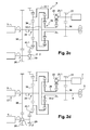
- FIGS. 2a-2d show a schematic representation of an exemplary embodiment of a transmission device 1 according to the invention.
- This transmission device 1 comprises two planetary gear trains 31 and 32.
- FIGS. 2b-2d illustrate the three modes of operation of this transmission device 1.
- the connecting device 8 is not shown.
- FIG. 2 shows the mechanical assembly 9 which comprises a first planetary gear 31 and a second epicyclic gear 32.
- a planet carrier 33.1 of the first train 31 is connected to a planet carrier 33.2 of the second train 32.
- the satellites of the first train 31 are referenced 331.
- the satellites of the second train 32 are referenced 332.
- a sun gear 34 of the first train 31 is connected to a crown 35 of the second train 32.
- the shaft 2 of the motor 3 is connected to the sun gear 34 of the first gear 31.
- the wheel shaft 4 is connected to the planet carrier 33.2 of the second gear 32.
- the shaft 11 of the second machine 7 is connected either to the shaft 4 of wheels 5 or to a sun gear 38 of the second gear 31. More precisely, the shaft 11 of the second machine 7 can be connected to the shaft 4 of wheels 5, with the aid of the first switching device 21.1, and through the first gear 22 and a first wheel 36. A ratio r1 corresponds to the ratio between the diameter of this first gear 22 and of this first wheel 36. In addition, the shaft 11 of the first machine 6 can be connected to the sun gear 38 of the second gear 32, with the aid of the first switching device 21.1, and via the second gear 23 and a second wheel 37. A ratio r2 corresponds to the ratio between the speed of rotation of the sun gear 38 and that of the second gear 29.
- the shaft 10 of the first machine 6 is connected either to the shaft 2 of the motor 3, or to a ring 40.1 of the first gear 31. More precisely, the shaft 10 of the first machine 6 can be connected to the shaft 2 of the motor 3, using the second switching device 21.2, and through the third gear 28 and a third wheel 39. A ratio r3 corresponds to the ratio between the diameter of the third gear 28 and of this third wheel 39. In addition, the shaft 10 of the first machine 6 can be connected to the ring gear 40.1 of the first gear 31, with the aid of the second switching device 21.2, and via fourth gear 29 and fourth wheel 40.2. A ratio r4 corresponds to the ratio between the diameter of this fourth gear 29 and this fourth wheel 37.
- the first element 24 of Figure 1 corresponds to the sun gear 34 of the first gear 31.
- the second element 25 of Figure 1 corresponds to the planet carrier 33.2 of the second gear 32.
- the third element 26 of Figure 1 corresponds to the planetary gear 38 of the second gear 32.
- the fourth element 27 corresponds to the gear 40.1 of the first gear 31.
- the reason for an epicyclic train corresponds to the ratio between the diameter of its crown and the diameter of its sun gear.
- the reason R1 of the first gear 31 is 2.3.
- the reason R2 of the second train 32 is 3,789.
- the first ratio r1 is -0.23.
- the second ratio r2 is 1.18.
- the third ratio r3 is less than the fourth ratio r4 which is equal to -0.45.
- the sign - indicates that the wheels are turning in opposite directions from each other.
- FIG. 2b illustrates the first mode of operation of the transmission device 1 of FIG. 2a.
- the first switching device 21.1 is connected to the first gear 22 and the second switching device is connected to the fourth gear 29.
- the first gear 22 is rotated by the first switching device 21.1, while the second gear 23 is not rotated.
- the fourth gear 29 is rotated by the second switching device 21.2, while the third gear 28 is not rotated.
- the third gear 28 and the third gear 39 are therefore shown in dotted lines to illustrate that they transmit no power to the shaft.
- the second epicyclic gear 32 is also shown in dotted lines. Indeed, even if the ring 35 of the second gear 32 is rotated, it does not transmit any power to the wheel shaft 4, since it is not connected to this shaft 4.
- the second machine 7 transmits its power to the shaft 4 of wheels 5 via the first gear 22 and the first wheel 36.
- the heat engine provides its power to the shaft 4 of wheel 5 via the first gear 31.
- the rotation speed of the shaft 4 of wheels 5 is equal to the speed of rotation of planet gears 33.1 and 33.2.
- FIG. 2c illustrates the second mode of operation of the transmission device 1 according to the invention.
- the shaft 2 of the thermal engine 3 is still connected to the sun gear 34 of the first gear 31.
- the wheel shaft 4 is still connected to the planet carrier 33.2 of the second gear 32.
- the first switching device 21.1 is connected to the second gear 23 and the second switching device 21.2 is connected to the fourth gear 29.
- the second gear 23 is rotated by the first switching device 21.1. while the second gear 23 is not rotated.
- the fourth gear 29 is rotated by the first switching device 21.1, while the third gear 28 is not rotated.
- first gear 22 and the first wheel 36 are shown in dotted lines, as well as the fourth gear 29 and the fourth wheel 39.
- This dashed representation illustrates the fact that they do not transmit power to the shaft 4 of FIG. wheels 5.
- FIG. 2d illustrates the third mode of operation of the transmission device 1 according to the invention.
- the shaft 2 of the thermal engine 3 is still connected to the sun gear 34 of the first gear 31.
- the wheel shaft 4 is still connected to the planet carrier 33.2 of the second gear 32.
- the first switching device 21.1 is connected to the second gear 23, and the second switching device 21.2 is connected to the third gear 28.
- the second gear 23 is thus rotated by the first switching device 21.1. while the first gear 22 is not rotated.
- the third gear 28 is driven into rotation by the second switching device 21.1, while the fourth gear 29 is not rotated.
- first gear 22 and the first wheel 36 shown in dotted lines can not transmit power to the wheel shaft 4 5.
- the first gear 31 is also shown in dotted lines to illustrate the fact that it does not transmit more power to the shaft 4 of the wheels 5. Indeed, the ring 40.1 of the first gear 31 is rotated, but it is not connected to the shaft of the second machine 7.
- the power exchanges between the shafts of the machines 6 and 7, the shaft 2 of the motor 3 and the shaft 4 of the wheels 5 are made via the third gear 28 and the third wheel 39. as well as through the second train 32.
- Figure 3 shows curves 43 showing a rotational speed of the shaft 2 of the engine 3 in revolutions per minute, as a function of a vehicle speed in kilometers per hour.
- Each zone is limited by two straight lines, called adaptation rights. These adaptation lines correspond to gear ratios for which the power derived in the electrical chain is zero. Each zone corresponds to a mode of operation of the transmission device 1 according to the invention. Indeed, two adaptation lines are associated with each mode.
- a first adaptation line 44 and a second adaptation line 45 are associated with the first mode of operation of the transmission device 1.
- This first mode of operation is used for low transmission ratios.
- This first mode is implemented in particular when starting the vehicle or when the vehicle has a speed between 0 and 15 km / h, for a rotation speed of the shaft of the engine of 1000 rpm.
- This first mode is also implemented for the rear steps of the vehicle.
- the second adaptation line 45 and a third adaptation line 46 are associated with the second mode of operation. This second mode is implemented for average transmission ratios.
- the third adaptation right 46 and a fourth straight adaptation 47 are associated with the third mode of operation. This third mode is implemented for transmission ratios longer than those implemented in the second mode.
- the second and third modes are implemented after the vehicle starts, when the vehicle is operating forward.
- each curve 43 corresponds a power derived in the electrical chain.
- one of the curves 43 close to the adaptation lines of one zone corresponds to a power derived from 10KW, while another curve further from the adaptation lines corresponds to a power derived in the electrical chain of 18KW.
- a rotation speed of a shaft of one of the machines 6 or 7 is zero. More specifically, on the second straight line 45 of adaptation, the rotation speed WA of the shaft 10 of the first machine 6 is zero. On the third adaptation line 46, the rotation speed WB of the shaft 11 of the second machine 7 is zero.
- the power derived in the electrical chain is zero.
- the power of the engine 2 is thus transmitted directly by the mechanical way to the shaft 4 of wheels 5.
- Each adaptation straight line corresponds to a ratio of reduction between the speed of rotation of the shaft 2 of the motor 3 and a rotation speed of the shaft 4 of wheels 5.
- the transition from one mode to another makes it possible to lighten the stress exerted on the shafts 10 and 11 of the machines 6 and 7 around their maximum speed.
- the second machine 7 in the first mode, the second machine 7 is in direct contact with the wheel shaft 4.
- the rotational speed WB of the shaft 11 of this second machine 7 thus increases very rapidly in proportion to the speed of rotation. this wheel shaft 4 5.
- the rotation speed WB of the shaft 11 of the second machine 7 reaches its maximum speed.
- the rotation speed WA of the shaft 10 of the first machine 6 is zero. If the speed of the vehicle increases, then we go to the second mode of operation.
- the rotational speed WA of the shaft 10 of the first machine 6 and the rotation speed WB of the shaft 11 of the second machine 7 are lower than their maximum speed.
- the transmission device 1 according to the invention makes it possible to limit the power transmitted by the electric chain to 12 kilowatts. Whereas for existing devices with only one mode of operation, the machines transmit about four times more power, and for existing devices with only two operating modes the machines transmit a power of about 18 kilowatts.
- the machines used in the device according to the invention are therefore more compact than the machines of the devices of the state of the art.
- the control device 30 controls the mode changes on the adaptation lines, when the power derived in the electrical chain is zero.
- This change of mode on the adaptation lines makes it possible to move the switching device 21.1 or 21.2 from one position to another without effort. Indeed, the torque that is applied to the shaft along which moves the switching device 21.1 or 21.2 is then zero.
- control device 30 controls mode changes on lines different from the adaptation lines, such as line 48 or line 49. These lines 48 and 49 are represented in dotted lines.
- the control device 30 then sends control signals O1 and O2 to the inverters 12 and 13 associated with the machines 6 and 7, so as to compensate for a difference in rotational speed which exists between the shaft of the machine 6 or 7 and an element to be connected.
- additional energy is supplied to the machine 6 or 7 via a storage system.
- This storage system such as a battery or a super capacitor is connected on an electric bus that connects the two machines.
- Figures 4a-4c show steps of a displacement of the second switching device 21.1.
- This second switching device 21.2 allows the shaft of the first machine 6 to catch either the third gear 28 or the fourth gear 29.
- the switching device 21.1 comprises a clutch 51 and a fork 53.
- the clutch 51 moves along the shaft 10 of the first machine 6 which has a shaft 52 of rotation.
- the fork 53 is hooked to the clutch 51. More specifically, this fork 53 comprises two arms 53.1 and 53.2 which bear on shoulders 54 and 55 of the clutch 51.
- This fork 53 is moved using a current motor. continued. A rotation of this motor is controlled by the signal O3 emitted by the control device 30.
- the clutch 51 is in a first position P1. In this first position P1, the clutch 51 is engaged with the third gear 28. The fourth gear 29 is not rotated.
- the fork 53 moves the dog 51 from the first position to a second position P2. During this movement, the dog 51 disengages from the first gear 28. In this position, the dog 51 engages neither the third gear 28 nor the fourth gear 29.
- the fork 53 moves the dog 51 from the second position P2 to a third position P3.
- the clutch 51 engages in the fourth gear 29.
- the clutch 51 is engaged with the fourth gear 29 so as to be able to drive it in rotation.
- the third gear 28 is not rotated.
- the clutch 51 comprises tabs 56 and 57 oriented axially relative to the axis 52.
- the gears 28 and 29 respectively comprise a groove 58 and a groove 59 on their peripheries. These grooves 58 and 59 are oriented axially with respect to the axis 52. These grooves 58 and 59 are intended to accommodate the tongues 56 and 57, so that the clutch 51 can rotating the gears 28 and 29.
- the clutch 51 has teeth that engage with teeth of the gears 28 and 29 located on the periphery of their inner diameter.
- the displacement of the dog 51 is reversible. Indeed, the dog 51 can also pass from a hooking with the fourth gear 29 to a catch with the third gear 28.
- the dog 51 has the advantage of dissipating very little energy.
- the switching device used is a clutch.
- the first switching device 21.1 is made in the same way as the switching device 21.2 which has just been described.
Landscapes
- Engineering & Computer Science (AREA)
- Mechanical Engineering (AREA)
- Transportation (AREA)
- Chemical & Material Sciences (AREA)
- Combustion & Propulsion (AREA)
- Automation & Control Theory (AREA)
- Power Engineering (AREA)
- General Engineering & Computer Science (AREA)
- Structure Of Transmissions (AREA)
- Electric Propulsion And Braking For Vehicles (AREA)
- Arrangement Of Transmissions (AREA)
- Hybrid Electric Vehicles (AREA)
- Hydraulic Clutches, Magnetic Clutches, Fluid Clutches, And Fluid Joints (AREA)
Priority Applications (3)
| Application Number | Priority Date | Filing Date | Title |
|---|---|---|---|
| EP06300214A EP1832460B1 (de) | 2006-03-08 | 2006-03-08 | Verzweigtes schaltbares elektromechanisches Getriebe und dessen Steuerung |
| DE602006011122T DE602006011122D1 (de) | 2006-03-08 | 2006-03-08 | Verzweigtes schaltbares elektromechanisches Getriebe und dessen Steuerung |
| AT06300214T ATE452042T1 (de) | 2006-03-08 | 2006-03-08 | Verzweigtes schaltbares elektromechanisches getriebe und dessen steuerung |
Applications Claiming Priority (1)
| Application Number | Priority Date | Filing Date | Title |
|---|---|---|---|
| EP06300214A EP1832460B1 (de) | 2006-03-08 | 2006-03-08 | Verzweigtes schaltbares elektromechanisches Getriebe und dessen Steuerung |
Publications (2)
| Publication Number | Publication Date |
|---|---|
| EP1832460A1 true EP1832460A1 (de) | 2007-09-12 |
| EP1832460B1 EP1832460B1 (de) | 2009-12-16 |
Family
ID=36650070
Family Applications (1)
| Application Number | Title | Priority Date | Filing Date |
|---|---|---|---|
| EP06300214A Expired - Lifetime EP1832460B1 (de) | 2006-03-08 | 2006-03-08 | Verzweigtes schaltbares elektromechanisches Getriebe und dessen Steuerung |
Country Status (3)
| Country | Link |
|---|---|
| EP (1) | EP1832460B1 (de) |
| AT (1) | ATE452042T1 (de) |
| DE (1) | DE602006011122D1 (de) |
Cited By (2)
| Publication number | Priority date | Publication date | Assignee | Title |
|---|---|---|---|---|
| WO2013017219A1 (de) * | 2011-08-03 | 2013-02-07 | Volkswagen Aktiengesellschaft | Hybridantriebsordnung für ein kraftfahrzeug |
| DE102018219607A1 (de) * | 2018-11-16 | 2020-05-20 | Zf Friedrichshafen Ag | Getriebevorrichtung für ein Hybridfahrzeug |
Citations (7)
| Publication number | Priority date | Publication date | Assignee | Title |
|---|---|---|---|---|
| EP1097830A1 (de) * | 1999-11-03 | 2001-05-09 | Renault | Hybridantriebsgruppe mit mindestens zwei Planetenradgetrieben |
| FR2832357A1 (fr) | 2001-11-21 | 2003-05-23 | Peugeot Citroen Automobiles Sa | Dispositif de transmission de puissance a au moins deux trains epicycloidaux |
| US20030100395A1 (en) * | 2001-11-28 | 2003-05-29 | Kazuyoshi Hiraiwa | Powertrain for hybrid electric vehicles |
| JP2005297786A (ja) * | 2004-04-12 | 2005-10-27 | Toyota Motor Corp | ハイブリッド車の駆動装置 |
| JP2006029431A (ja) * | 2004-07-15 | 2006-02-02 | Nissan Motor Co Ltd | ハイブリッド車両の制御装置 |
| US20060025264A1 (en) * | 2004-07-29 | 2006-02-02 | Henryk Sowul | Electrically variable transmission arrangement with transfer gear between motor/generators |
| WO2006032819A1 (fr) * | 2004-09-24 | 2006-03-30 | Peugeot Citroen Automobiles Sa | Dispositif de transmission de puissance et procede mettant en oeuvre ce dispositif |
-
2006
- 2006-03-08 AT AT06300214T patent/ATE452042T1/de not_active IP Right Cessation
- 2006-03-08 EP EP06300214A patent/EP1832460B1/de not_active Expired - Lifetime
- 2006-03-08 DE DE602006011122T patent/DE602006011122D1/de not_active Expired - Lifetime
Patent Citations (7)
| Publication number | Priority date | Publication date | Assignee | Title |
|---|---|---|---|---|
| EP1097830A1 (de) * | 1999-11-03 | 2001-05-09 | Renault | Hybridantriebsgruppe mit mindestens zwei Planetenradgetrieben |
| FR2832357A1 (fr) | 2001-11-21 | 2003-05-23 | Peugeot Citroen Automobiles Sa | Dispositif de transmission de puissance a au moins deux trains epicycloidaux |
| US20030100395A1 (en) * | 2001-11-28 | 2003-05-29 | Kazuyoshi Hiraiwa | Powertrain for hybrid electric vehicles |
| JP2005297786A (ja) * | 2004-04-12 | 2005-10-27 | Toyota Motor Corp | ハイブリッド車の駆動装置 |
| JP2006029431A (ja) * | 2004-07-15 | 2006-02-02 | Nissan Motor Co Ltd | ハイブリッド車両の制御装置 |
| US20060025264A1 (en) * | 2004-07-29 | 2006-02-02 | Henryk Sowul | Electrically variable transmission arrangement with transfer gear between motor/generators |
| WO2006032819A1 (fr) * | 2004-09-24 | 2006-03-30 | Peugeot Citroen Automobiles Sa | Dispositif de transmission de puissance et procede mettant en oeuvre ce dispositif |
Non-Patent Citations (1)
| Title |
|---|
| PATENT ABSTRACTS OF JAPAN vol. 2003, no. 12 5 December 2003 (2003-12-05) * |
Cited By (4)
| Publication number | Priority date | Publication date | Assignee | Title |
|---|---|---|---|---|
| WO2013017219A1 (de) * | 2011-08-03 | 2013-02-07 | Volkswagen Aktiengesellschaft | Hybridantriebsordnung für ein kraftfahrzeug |
| CN103857549A (zh) * | 2011-08-03 | 2014-06-11 | 大众汽车有限公司 | 用于汽车的混合驱动装置 |
| CN103857549B (zh) * | 2011-08-03 | 2016-09-07 | 大众汽车有限公司 | 用于汽车的混合驱动装置 |
| DE102018219607A1 (de) * | 2018-11-16 | 2020-05-20 | Zf Friedrichshafen Ag | Getriebevorrichtung für ein Hybridfahrzeug |
Also Published As
| Publication number | Publication date |
|---|---|
| DE602006011122D1 (de) | 2010-01-28 |
| ATE452042T1 (de) | 2010-01-15 |
| EP1832460B1 (de) | 2009-12-16 |
Similar Documents
| Publication | Publication Date | Title |
|---|---|---|
| EP2001719B1 (de) | Kraftübertragungsverfahren | |
| EP1453694B9 (de) | Kraftübertragungsvorrichtung mit mindestens zwei planetengetriebezügen | |
| EP1877273B1 (de) | Schaltvorrichtung für ein kraftfahrzeug und ihre verwendung | |
| WO2006032819A1 (fr) | Dispositif de transmission de puissance et procede mettant en oeuvre ce dispositif | |
| EP1875104B1 (de) | Leistungsübertragungsvorrichtung für ein mit einem freilaufantrieb, der eine ölpumpe antreibt, ausgestatteten kraftfahrzeug | |
| WO2011072765A1 (fr) | Procede de pilotage d'un dispositif de motorisation de vehicule hybride, et dispositif associe | |
| WO2009068796A1 (fr) | Dispositif de transmission de puissance entre une sortie d'un moteur thermique et un arbre de roues et utilisation de ce dispositif | |
| FR2885106A1 (fr) | Procede de blocage de roues d'un vehicule hybride a l'arret et dispositif de transmission associe | |
| WO2006100404A1 (fr) | Dispositif de transmission de puissance entre une sortie d'un moteur thermique et un arbre de roues et procede de transmission de puissance associe | |
| EP1832460B1 (de) | Verzweigtes schaltbares elektromechanisches Getriebe und dessen Steuerung | |
| WO2015090876A1 (fr) | Groupe motopropulseur avec un dispositif de transmission à variation de vitesse, en particulier pour véhicule hybride | |
| WO2019122553A1 (fr) | Chaîne de traction améliorée de véhicule automobile comprenant deux machines électriques tournantes | |
| EP1789722B1 (de) | Antriebseinheit für ein hybridfahrzeug und verfahren | |
| EP3230106B1 (de) | Antriebsstrang zum antreiben eines kraftfahrzeugs mit wechselgetriebevorrichtung mit einem dreifachen planetengetriebesatz und insbesondere ein antriebsstrang für ein hybridfahrzeug | |
| FR3123283A1 (fr) | Sous-ensemble hybride d’entraînement d’un véhicule, groupe moteur hybride et procédé d’entraînement hybride | |
| FR2923420A1 (fr) | Vehicule automobile comportant des moyens d'optimisation de la consommation des accesoires par transmission selective | |
| EP1792101B1 (de) | Vorrichtung zur leistungsübertragung in einem fahrzeug zwischen der wärmekraftmaschinenwelle und einer radachse | |
| FR2967620A1 (fr) | Vehicule hybride a deux trains d'engrenages epicycloidaux a derivation de puissance et a efficacite energetique amelioree | |
| EP4499442B1 (de) | Kraftfahrzeug mit elektrischem antrieb und verfahren zum steuern des kraftfahrzeugs | |
| WO2015086325A1 (fr) | Groupe motopropulseur avec un dispositif de transmission à variation de vitesse, en particulier pour véhicule hybride | |
| FR3135023A1 (fr) | Chaîne de traction pour véhicule hybride équipé d’un train épicycloïdal et procédé de fonctionnement | |
| FR3161396A1 (fr) | Dispositif de contrôle d’une transmission avec accouplement piloté | |
| FR3097810A1 (fr) | Système de transmission électrique, notamment 48V, pour véhicule doté d’un prolongateur d’autonomie et procédé de pilotage de ce système | |
| WO2015092294A1 (fr) | Système électromécanique de récupération d'énergie cinétique | |
| FR3041910A1 (fr) | Dispositif de selection de vitesses d’un vehicule hybride |
Legal Events
| Date | Code | Title | Description |
|---|---|---|---|
| PUAI | Public reference made under article 153(3) epc to a published international application that has entered the european phase |
Free format text: ORIGINAL CODE: 0009012 |
|
| AK | Designated contracting states |
Kind code of ref document: A1 Designated state(s): AT BE BG CH CY CZ DE DK EE ES FI FR GB GR HU IE IS IT LI LT LU LV MC NL PL PT RO SE SI SK TR |
|
| AX | Request for extension of the european patent |
Extension state: AL BA HR MK YU |
|
| 17P | Request for examination filed |
Effective date: 20070924 |
|
| 17Q | First examination report despatched |
Effective date: 20071029 |
|
| AKX | Designation fees paid |
Designated state(s): AT BE BG CH CY CZ DE DK EE ES FI FR GB GR HU IE IS IT LI LT LU LV MC NL PL PT RO SE SI SK TR |
|
| GRAP | Despatch of communication of intention to grant a patent |
Free format text: ORIGINAL CODE: EPIDOSNIGR1 |
|
| RIC1 | Information provided on ipc code assigned before grant |
Ipc: F16H 3/72 20060101ALI20090619BHEP Ipc: B60W 20/00 20060101ALI20090619BHEP Ipc: B60K 6/365 20071001ALI20090619BHEP Ipc: B60K 6/445 20071001AFI20090619BHEP |
|
| GRAS | Grant fee paid |
Free format text: ORIGINAL CODE: EPIDOSNIGR3 |
|
| GRAA | (expected) grant |
Free format text: ORIGINAL CODE: 0009210 |
|
| AK | Designated contracting states |
Kind code of ref document: B1 Designated state(s): AT BE BG CH CY CZ DE DK EE ES FI FR GB GR HU IE IS IT LI LT LU LV MC NL PL PT RO SE SI SK TR |
|
| REG | Reference to a national code |
Ref country code: GB Ref legal event code: FG4D Free format text: NOT ENGLISH |
|
| REG | Reference to a national code |
Ref country code: CH Ref legal event code: EP |
|
| REG | Reference to a national code |
Ref country code: IE Ref legal event code: FG4D |
|
| REF | Corresponds to: |
Ref document number: 602006011122 Country of ref document: DE Date of ref document: 20100128 Kind code of ref document: P |
|
| REG | Reference to a national code |
Ref country code: GB Ref legal event code: 746 Effective date: 20100215 |
|
| REG | Reference to a national code |
Ref country code: NL Ref legal event code: VDEP Effective date: 20091216 |
|
| PG25 | Lapsed in a contracting state [announced via postgrant information from national office to epo] |
Ref country code: SE Free format text: LAPSE BECAUSE OF FAILURE TO SUBMIT A TRANSLATION OF THE DESCRIPTION OR TO PAY THE FEE WITHIN THE PRESCRIBED TIME-LIMIT Effective date: 20091216 Ref country code: FI Free format text: LAPSE BECAUSE OF FAILURE TO SUBMIT A TRANSLATION OF THE DESCRIPTION OR TO PAY THE FEE WITHIN THE PRESCRIBED TIME-LIMIT Effective date: 20091216 Ref country code: LT Free format text: LAPSE BECAUSE OF FAILURE TO SUBMIT A TRANSLATION OF THE DESCRIPTION OR TO PAY THE FEE WITHIN THE PRESCRIBED TIME-LIMIT Effective date: 20091216 |
|
| LTIE | Lt: invalidation of european patent or patent extension |
Effective date: 20091216 |
|
| PG25 | Lapsed in a contracting state [announced via postgrant information from national office to epo] |
Ref country code: LV Free format text: LAPSE BECAUSE OF FAILURE TO SUBMIT A TRANSLATION OF THE DESCRIPTION OR TO PAY THE FEE WITHIN THE PRESCRIBED TIME-LIMIT Effective date: 20091216 Ref country code: SI Free format text: LAPSE BECAUSE OF FAILURE TO SUBMIT A TRANSLATION OF THE DESCRIPTION OR TO PAY THE FEE WITHIN THE PRESCRIBED TIME-LIMIT Effective date: 20091216 Ref country code: PL Free format text: LAPSE BECAUSE OF FAILURE TO SUBMIT A TRANSLATION OF THE DESCRIPTION OR TO PAY THE FEE WITHIN THE PRESCRIBED TIME-LIMIT Effective date: 20091216 |
|
| PG25 | Lapsed in a contracting state [announced via postgrant information from national office to epo] |
Ref country code: AT Free format text: LAPSE BECAUSE OF FAILURE TO SUBMIT A TRANSLATION OF THE DESCRIPTION OR TO PAY THE FEE WITHIN THE PRESCRIBED TIME-LIMIT Effective date: 20091216 |
|
| REG | Reference to a national code |
Ref country code: IE Ref legal event code: FD4D |
|
| PG25 | Lapsed in a contracting state [announced via postgrant information from national office to epo] |
Ref country code: IE Free format text: LAPSE BECAUSE OF FAILURE TO SUBMIT A TRANSLATION OF THE DESCRIPTION OR TO PAY THE FEE WITHIN THE PRESCRIBED TIME-LIMIT Effective date: 20091216 Ref country code: IS Free format text: LAPSE BECAUSE OF FAILURE TO SUBMIT A TRANSLATION OF THE DESCRIPTION OR TO PAY THE FEE WITHIN THE PRESCRIBED TIME-LIMIT Effective date: 20100416 Ref country code: RO Free format text: LAPSE BECAUSE OF FAILURE TO SUBMIT A TRANSLATION OF THE DESCRIPTION OR TO PAY THE FEE WITHIN THE PRESCRIBED TIME-LIMIT Effective date: 20091216 Ref country code: EE Free format text: LAPSE BECAUSE OF FAILURE TO SUBMIT A TRANSLATION OF THE DESCRIPTION OR TO PAY THE FEE WITHIN THE PRESCRIBED TIME-LIMIT Effective date: 20091216 Ref country code: BG Free format text: LAPSE BECAUSE OF FAILURE TO SUBMIT A TRANSLATION OF THE DESCRIPTION OR TO PAY THE FEE WITHIN THE PRESCRIBED TIME-LIMIT Effective date: 20100316 Ref country code: ES Free format text: LAPSE BECAUSE OF FAILURE TO SUBMIT A TRANSLATION OF THE DESCRIPTION OR TO PAY THE FEE WITHIN THE PRESCRIBED TIME-LIMIT Effective date: 20100327 Ref country code: NL Free format text: LAPSE BECAUSE OF FAILURE TO SUBMIT A TRANSLATION OF THE DESCRIPTION OR TO PAY THE FEE WITHIN THE PRESCRIBED TIME-LIMIT Effective date: 20091216 Ref country code: PT Free format text: LAPSE BECAUSE OF FAILURE TO SUBMIT A TRANSLATION OF THE DESCRIPTION OR TO PAY THE FEE WITHIN THE PRESCRIBED TIME-LIMIT Effective date: 20100416 |
|
| PG25 | Lapsed in a contracting state [announced via postgrant information from national office to epo] |
Ref country code: SK Free format text: LAPSE BECAUSE OF FAILURE TO SUBMIT A TRANSLATION OF THE DESCRIPTION OR TO PAY THE FEE WITHIN THE PRESCRIBED TIME-LIMIT Effective date: 20091216 Ref country code: CZ Free format text: LAPSE BECAUSE OF FAILURE TO SUBMIT A TRANSLATION OF THE DESCRIPTION OR TO PAY THE FEE WITHIN THE PRESCRIBED TIME-LIMIT Effective date: 20091216 |
|
| BERE | Be: lapsed |
Owner name: PEUGEOT CITROEN AUTOMOBILES SA Effective date: 20100331 |
|
| PLBE | No opposition filed within time limit |
Free format text: ORIGINAL CODE: 0009261 |
|
| STAA | Information on the status of an ep patent application or granted ep patent |
Free format text: STATUS: NO OPPOSITION FILED WITHIN TIME LIMIT |
|
| PG25 | Lapsed in a contracting state [announced via postgrant information from national office to epo] |
Ref country code: MC Free format text: LAPSE BECAUSE OF NON-PAYMENT OF DUE FEES Effective date: 20100331 Ref country code: CY Free format text: LAPSE BECAUSE OF FAILURE TO SUBMIT A TRANSLATION OF THE DESCRIPTION OR TO PAY THE FEE WITHIN THE PRESCRIBED TIME-LIMIT Effective date: 20091216 Ref country code: GR Free format text: LAPSE BECAUSE OF FAILURE TO SUBMIT A TRANSLATION OF THE DESCRIPTION OR TO PAY THE FEE WITHIN THE PRESCRIBED TIME-LIMIT Effective date: 20100317 |
|
| REG | Reference to a national code |
Ref country code: CH Ref legal event code: PL |
|
| 26N | No opposition filed |
Effective date: 20100917 |
|
| PG25 | Lapsed in a contracting state [announced via postgrant information from national office to epo] |
Ref country code: DK Free format text: LAPSE BECAUSE OF FAILURE TO SUBMIT A TRANSLATION OF THE DESCRIPTION OR TO PAY THE FEE WITHIN THE PRESCRIBED TIME-LIMIT Effective date: 20091216 |
|
| PG25 | Lapsed in a contracting state [announced via postgrant information from national office to epo] |
Ref country code: LI Free format text: LAPSE BECAUSE OF NON-PAYMENT OF DUE FEES Effective date: 20100331 Ref country code: CH Free format text: LAPSE BECAUSE OF NON-PAYMENT OF DUE FEES Effective date: 20100331 Ref country code: BE Free format text: LAPSE BECAUSE OF NON-PAYMENT OF DUE FEES Effective date: 20100331 |
|
| PG25 | Lapsed in a contracting state [announced via postgrant information from national office to epo] |
Ref country code: IT Free format text: LAPSE BECAUSE OF FAILURE TO SUBMIT A TRANSLATION OF THE DESCRIPTION OR TO PAY THE FEE WITHIN THE PRESCRIBED TIME-LIMIT Effective date: 20091216 |
|
| PG25 | Lapsed in a contracting state [announced via postgrant information from national office to epo] |
Ref country code: HU Free format text: LAPSE BECAUSE OF FAILURE TO SUBMIT A TRANSLATION OF THE DESCRIPTION OR TO PAY THE FEE WITHIN THE PRESCRIBED TIME-LIMIT Effective date: 20100617 Ref country code: LU Free format text: LAPSE BECAUSE OF NON-PAYMENT OF DUE FEES Effective date: 20100308 |
|
| PG25 | Lapsed in a contracting state [announced via postgrant information from national office to epo] |
Ref country code: TR Free format text: LAPSE BECAUSE OF FAILURE TO SUBMIT A TRANSLATION OF THE DESCRIPTION OR TO PAY THE FEE WITHIN THE PRESCRIBED TIME-LIMIT Effective date: 20091216 |
|
| PGFP | Annual fee paid to national office [announced via postgrant information from national office to epo] |
Ref country code: DE Payment date: 20150219 Year of fee payment: 10 |
|
| PGFP | Annual fee paid to national office [announced via postgrant information from national office to epo] |
Ref country code: GB Payment date: 20150226 Year of fee payment: 10 |
|
| REG | Reference to a national code |
Ref country code: FR Ref legal event code: PLFP Year of fee payment: 11 |
|
| REG | Reference to a national code |
Ref country code: DE Ref legal event code: R119 Ref document number: 602006011122 Country of ref document: DE |
|
| GBPC | Gb: european patent ceased through non-payment of renewal fee |
Effective date: 20160308 |
|
| PG25 | Lapsed in a contracting state [announced via postgrant information from national office to epo] |
Ref country code: DE Free format text: LAPSE BECAUSE OF NON-PAYMENT OF DUE FEES Effective date: 20161001 Ref country code: GB Free format text: LAPSE BECAUSE OF NON-PAYMENT OF DUE FEES Effective date: 20160308 |
|
| REG | Reference to a national code |
Ref country code: FR Ref legal event code: PLFP Year of fee payment: 12 |
|
| REG | Reference to a national code |
Ref country code: FR Ref legal event code: PLFP Year of fee payment: 13 |
|
| REG | Reference to a national code |
Ref country code: FR Ref legal event code: CA Effective date: 20180312 Ref country code: FR Ref legal event code: CD Owner name: PEUGEOT CITROEN AUTOMOBILES SA, FR Effective date: 20180312 |
|
| PGFP | Annual fee paid to national office [announced via postgrant information from national office to epo] |
Ref country code: FR Payment date: 20200220 Year of fee payment: 15 |
|
| PG25 | Lapsed in a contracting state [announced via postgrant information from national office to epo] |
Ref country code: FR Free format text: LAPSE BECAUSE OF NON-PAYMENT OF DUE FEES Effective date: 20210331 |