EP1832468B1 - Sitz eines Nutzfahrzeugs mit wendbarer Sitzfläche - Google Patents
Sitz eines Nutzfahrzeugs mit wendbarer Sitzfläche Download PDFInfo
- Publication number
- EP1832468B1 EP1832468B1 EP07003526A EP07003526A EP1832468B1 EP 1832468 B1 EP1832468 B1 EP 1832468B1 EP 07003526 A EP07003526 A EP 07003526A EP 07003526 A EP07003526 A EP 07003526A EP 1832468 B1 EP1832468 B1 EP 1832468B1
- Authority
- EP
- European Patent Office
- Prior art keywords
- seat
- hinge
- accordance
- axis
- holder shell
- Prior art date
- Legal status (The legal status is an assumption and is not a legal conclusion. Google has not performed a legal analysis and makes no representation as to the accuracy of the status listed.)
- Active
Links
Images


Classifications
-
- B—PERFORMING OPERATIONS; TRANSPORTING
- B60—VEHICLES IN GENERAL
- B60R—VEHICLES, VEHICLE FITTINGS, OR VEHICLE PARTS, NOT OTHERWISE PROVIDED FOR
- B60R7/00—Stowing or holding appliances inside vehicle primarily intended for personal property smaller than suit-cases, e.g. travelling articles, or maps
- B60R7/04—Stowing or holding appliances inside vehicle primarily intended for personal property smaller than suit-cases, e.g. travelling articles, or maps in driver or passenger space, e.g. using racks
- B60R7/043—Stowing or holding appliances inside vehicle primarily intended for personal property smaller than suit-cases, e.g. travelling articles, or maps in driver or passenger space, e.g. using racks mounted on or under a seat
-
- B—PERFORMING OPERATIONS; TRANSPORTING
- B60—VEHICLES IN GENERAL
- B60N—SEATS SPECIALLY ADAPTED FOR VEHICLES; VEHICLE PASSENGER ACCOMMODATION NOT OTHERWISE PROVIDED FOR
- B60N2/00—Seats specially adapted for vehicles; Arrangement or mounting of seats in vehicles
- B60N2/24—Seats specially adapted for vehicles; Arrangement or mounting of seats in vehicles for particular purposes or particular vehicles
- B60N2/30—Non-dismountable or dismountable seats storable in a non-use position, e.g. foldable spare seats
- B60N2/3038—Cushion movements
- B60N2/3063—Cushion movements by composed movement
Definitions
- the invention relates to a padded on the top seat, in particular a truck, according to the preamble of claim 1.
- a vehicle seat which comprises a backrest and a seat.
- the seat has a fixed seat base with a frame in which a cushion is inserted, which is removable.
- the cushion has a first and a second area lying one above the other.
- the first area is made of foam and serves as a seating surface for a passenger.
- the second area is made of solid plastic. He has at least one recess. The recess serves as a storage compartment when the pillow was turned over with the top of the first area down.
- a generic seat with a lower, a substantially approximately horizontal or slightly inclined seating surface having seat cushion part and a seat segment with a top and an opposite bottom.
- the seat segment is movably guided by guide means between a first and a second position. In the first position, the seat segment is recessed in the seat cushion part and forms with the top part of the seat surface of the seat cushion part. In the second position, the seat segment is opposite the seat surface the seat cushion part increases.
- the guide means are designed such that they each cause an inevitable turning movement by about 180 ° when transferring the seat segment between its two positions in addition to the vertical offset, so that the seat segment in the elevated second position with its underside facing away from the seat cushion part upwards.
- Object of the present invention is to provide a seat with a stationary backrest in the cab of a commercial vehicle, in which the interior of the seat remains accessible while the seat except for sitting, and a variety of other uses can be fed.
- the object is achieved in that the receiving tray is attached to a hinge which extends along the upper edge of a front of the seat and that the receiving tray of the seat is pivotally mounted about a, along the upper edge extending through the hinge axis and pivoting out of a Starting position is rotatably mounted about an axis perpendicular to the axis extending.
- the advantage of the invention is that the upholstered on the top seat due to the pivoting mechanism according to the invention can be converted into a predominantly flat surface, which is accessible and / or used as a footprint of, for example, electrical onboard equipment.
- Electrical on-board equipment may be, for example, personal computers, electronic communications or the like.
- the electrical equipment on board are detachable but captively secured to the footprint. They are in combination with the footprint with the help of the pivoting pivot mechanism of the type in an initial position of the seat brought that the on-board equipment facing the roadway, engages in at least one opening in the seat and the upholstery of the seat faces the headliner of the vehicle cabin.
- the position is referred to, in which the seat rests on the seat in an approximately parallel position to the road and facing with its padding the headliner of the cab and with its back to the vehicle floor.
- the seat may be pivotable by means of a hinge extending along the upper edge of the front of the seat from a starting position parallel to the roadway.
- the seat is by using a hinge force-saving and easily-reschwenkbar from its initial position on the seat.
- the receiving tray after pivoting about 90 ° from the starting position to be rotatable about an axis perpendicular to the hinge, approximately through the center axis of rotation.
- the axis of rotation passing through the hinge is connected thereto.
- the receiving tray in a relation to the starting position rotated by 180 ° about the rotational axis position, forward in the direction of the seat, in a position corresponding to the starting position can be pivoted.
- the receiving tray may be accessible on its rear side.
- the seat may be supported to ensure accessibility.
- the back of the seat may have a puncture-resistant coating.
- the back of the seat may have a structured footprint for depositing objects.
- the footprint may include means for releasably securing the parked items.
- the rear side of the seat may have receiving devices for the captive retention of the on-board equipment. It is conceivable to provide holders for papers and cards or to clip on board tools in the back.
- the seat for releasable anchoring relative to the seat foot may have a detent which is arranged on the side of the seat foot which lies opposite the hinge.
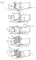
- Fig. 1 shows the seat of the commercial vehicle in different positions.
- the seat 1 shows Fig. 1 a seat base 2, on whose, the rear wall of the cab (not shown) facing the end 4 by means of two opposing cheeks 5, a backrest 6 is arranged on the seat base 2.
- the seat 1 comprises a receiving tray 7 with its enclosures 8 and a seat cushion 10 arranged within the enclosures 8.
- the seat cushion 10 is shown.
- a hinge 13 extends.
- the hinge 13 is connected via a tongue 14 with the receiving tray 7.
- the receiving tray 7 of the seat 1 is pivotally mounted about the axis 15 in association with the hinge 13. It is conceivable that the hinge alternatively extends along the upper edge of one of the two sides of the seat base 2.
- the pan and / or rotary movement is manually or z. B. also operated by a motor feasible.
- the Fig. 2 of the Fig. 1 shows a seat 1 after Fig. 1 , Contrary to the Fig. 1 However, here is the receiving tray 7 with the seat cushion 10 disposed therein about the hinge 13 about the axis 15 at an angle of about 90 ° relative to the starting position 23 in the direction of the roof of the cab (not shown) swung out.
- the pin 20 are to receive, which are arranged on the rear edge 8 of the receiving tray 7.
- the pins 20 are provided for releasable engagement in the latches 19.
- Fig. 3 shows the seat 1 as in Fig. 2 ,
- the attached to the tongue 14 receiving tray 7 is rotated counterclockwise with the seat pad 10 brought into contact therein by 90 ° about the approximately perpendicular to the hinge 13 extending axis of rotation 16.
- the tongue 14 connected to the hinge 13 points away from the backrest 6 and carries the axis of rotation 16.
- Fig. 4 shows the seat 1 according to the Fig. 3 ,
- the receiving tray 7 and with it the seat cushion 10 are opposite to the Fig. 3 counterclockwise rotated about the rotation axis 16 by a further 90 °.
- the arranged in the receiving tray 7 seat cushion 10 is the backrest 6 faces.
- the pivoting rotary mechanism can be carried out while driving or by a person.
- the seat foot 2 may e.g. take the form of a base, which provides an additional storage space 9 under the seat 1 in the interior of the seat base.
- the storage space 9 is closed by the seat 1 upwards, regardless of whether the back of the seat 1 is used as a seat, footprint 26 or as a stand space. It is conceivable, depending on the height of the cab to make the seat 2 variable in height.
- the seat 1 in a the respective leg length of the user corresponding seating is convertible.
- the seat 1 may also be usable as a step 24 provided with a walkable pad 22 which may e.g. allows access to the roof of the cab through an opening in the roof of the cab.
- the seat 1 and the seat 2 are fixed as needed or anchored anchored to the floor of the cab.
- the receiving tray 7 of the seat 1 has on its rear side 21 a tread-resistant covering 22. This ensures that the passenger, who stands on the tread-resistant lining 22, even when contaminated by dirt, snow or ice, finds a secure fit.
- the extending through the hinge 13 axis 15 causes the receiving tray 7 is positionally stable in all positions of its pivotal and rotational movement and does not need to be removed from its holder relative to the tongue 14. A release of the receiving tray 7 from the seat 2 and their temporary storage are therefore not required.
- the hinge 13 opposite the skirt 8 of the receiving tray 7 has a releasable lock 19 relative to the seat 2.
- the lock 19 can be arranged on each upper edge 11 of the side walls 3 of the seat base 2 and causes a firm and secure anchoring of the receiving tray 7 both for the use of the seat cushion 10 by the passenger and for the back 21 of the receiving tray 7 as a non-tilting base for the passenger or any item.
Landscapes
- Engineering & Computer Science (AREA)
- Mechanical Engineering (AREA)
- Aviation & Aerospace Engineering (AREA)
- Transportation (AREA)
- Seats For Vehicles (AREA)
- Chair Legs, Seat Parts, And Backrests (AREA)
- Passenger Equipment (AREA)
Description
- Die Erfindung bezieht sich auf einen auf der Oberseite gepolsterten Sitz, insbesondere eines Lastkraftwagens, gemäß dem Oberbegriff des Anspruchs 1.
- Aus der
DE 37 050 59 A1 ist ein Kraftfahrzeugsitz mit nach vorn auf den Sitzteil klappbarer Rückenlehne bekannt. Auf der Rückseite im oberen Bereich der Rückenlehne ist ein plattenförmiger Wandteil schwenkbar gelagert, an dem um eine dazu parallele Schwenkachse ein weiterer plattenförmiger Wandteil schwenkbar gehalten ist. Beide Wandteile können aneinander geklappt an die Rückseite der Rückenlehne angeklappt werden und bilden dann bei nach vorn umgeklappter Rückenlehne eine harte, ebene Ablagefläche für Gepäck. Ferner können beide Wandteile zusammen relativ zur umgeklappten Rückenlehne in eine Hochlage hochgeklappt und so festgestellt werden, so dass ein nach oben offener Behälter für Gepäckgut entsteht, der bei Abschwenken des zweiten Wandteils vom ersten Wandteil und verriegeln mittels der Verriegelungseinrichtung der Rückenlehne noch verschließbar ist, wobei der zweite Wandteil den Behälterdeckel bildet. Diese Konstruktionsweise hat sich in der Vergangenheit bewährt, um im Inneren des Fahrerhauses eine Ablagefläche bzw. einen offenen Behälter für Gepäckgut zu schaffen. - Aus der
FR 2 783 217 - Aus der
DE 201 10 630 U1 ist ein gattungsgemäßer Sitz bekannt, mit einem unteren, eine im Wesentlichen etwa horizontale oder leicht geneigte Sitzfläche aufweisenden Sitzpolsterteil und einem Sitzsegment mit einer Oberseite und einer gegenüberliegenden Unterseite. Das Sitzsegment ist über Führungsmittel zwischen einer ersten und einer zweiten Stellung bewegbar geführt. In der ersten Stellung ist das Sitzsegment in dem Sitzpolsterteil versenkt und bildet mit der Oberseite einen Teil der Sitzfläche des Sitzpolsterteils. In der zweiten Stellung ist das Sitzsegment aus der Sitzfläche heraus gegenüber dem Sitzpolsterteil erhöht angeordnet. Die Führungsmittel sind derart ausgebildet, dass sie beim Überführen des Sitzsegmentes zwischen seinen beiden Stellungen zusätzlich zu dem Höhenversatz jeweils eine zwangsläufige Wendebewegung um etwa 180° bewirken, so dass das Sitzsegment in der erhöhten zweiten Stellung mit seiner Unterseite von dem Sitzpolsterteil weg nach oben weist. - Aufgabe der vorliegenden Erfindung ist es, im Fahrerhaus eines Nutzfahrzeugs einen Sitz mit einer ortsfesten Rückenlehne zu schaffen, bei dem das Innere des Sitzfußes zugänglich bleibt, während die Sitzfläche außer zum Sitzen, auch einer Vielzahl anderer Nutzungen zuführbar ist.
- Die Aufgabe wird erfindungsgemäß dadurch gelöst, dass die Aufnahmeschale an einem Scharnier befestigt ist, das entlang der Oberkante einer Vorderseite des Sitzfußes verläuft und dass die Aufnahmeschale des Sitzes um eine, entlang der Oberkante durch das Scharnier verlaufenden Achse schwenkbar gelagert ist und nach Herausschwenken aus einer Ausgangsposition um eine senkrecht zur Achse verlaufende Achse drehbar gelagert ist.
- Der Vorteil der Erfindung besteht darin, dass der auf der Oberseite gepolsterte Sitz auf Grund des erfindungsgemäßen Schwenk-Drehmechanismus in eine vorwiegend ebene Oberfläche umrüstbar ist, die betretbar ist und/ oder als Stellfläche von beispielsweise elektrischen Bordausrüstungen verwendbar ist. Elektrische Bordausrüstungen können z.B. Personal Computer, elektronische Kommunikationsmittel oder ähnliches sein. Die elektrischen Bordausrüstungen sind lösbar aber verliersicher an der Stellfläche befestigbar. Sie sind im Verbund mit der Stellfläche mit Hilfe des Schwenk-Drehmechanismus der Art in eine Ausgangsposition des Sitzes bringbar, dass die Bordausrüstung zur Fahrbahn weisend, in mindestens eine Öffnung im Sitzfuß eingreift und die Polsterung des Sitzes dem Dachhimmel der Fahrzeugkabine zugewandt ist. Als Ausgangsposition des Sitzes wird die Position bezeichnet, in der der Sitz auf dem Sitzfuß in einer etwa parallelen Position zur Fahrbahn aufliegt und mit seiner Polsterung dem Dachhimmel der Fahrerhauses und mit seiner Rückseite dem Fahrzeugboden zugekehrt ist.
- Gemäß der Erfindung kann der Sitz mittels eines, sich entlang der Oberkante der Vorderseite des Sitzes erstreckenden Scharniers aus einer, parallel zur Fahrbahn angeordneten Ausgangsposition schwenkbar sein. Die Sitzfläche ist durch zu Hilfenahme eines Scharniers kraftsparend und leicht aus ihrer Ausgangsposition auf dem Sitzfuß herausschwenkbar.
- Gemäß einer Ausführungsform der Erfindung kann die Aufnahmeschale nach Herausschwenken um etwa 90° aus der Ausgangsposition um eine, senkrecht zum Scharnier, etwa durch dessen Mitte verlaufende Drehachse drehbar sein.
- Gemäß einer Ausführungsform der Erfindung kann die durch das Scharnier verlaufende Drehachse mit diesem verbunden ist.
- Gemäß einer Ausführungsform der Erfindung kann die Aufnahmeschale in einer gegenüber der Ausgangsposition um 180° um die Drehachse gedrehten Stellung, nach vorne in Richtung auf den Sitzfuß, in eine der Ausgangsposition entsprechende Position schwenkbar sein.
- Gemäß einer Ausführungsform der Erfindung kann die Aufnahmeschale auf ihrer Rückseite betretbar sein.
- Gemäß einer Ausführungsform der Erfindung kann der Sitz zur Sicherstellung der Betretbarkeit abgestützt sein.
- Gemäß einer Ausführungsform der Erfindung kann die Rückseite des Sitzes einen trittfesten Belag aufweisen.
- Gemäß einer Ausführungsform der Erfindung kann die Rückseite des Sitzes eine strukturierte Stellfläche zum Abstellen von Gegenständen aufweisen.
- Gemäß einer Ausführungsform der Erfindung kann die Stellfläche Vorrichtungen zur lösbaren Befestigung der abgestellten Gegenstände aufweisen.
- Gemäß einer Ausführungsform der Erfindung kann die Rückseite des Sitzes Aufnahmevorrichtungen zur verliersicheren Halterung der Bordausrüstung aufweisen. Es ist denkbar, Halterungen für Papiere und Karten vorzusehen oder in der Rückseite Bordwerkzeug einzuklipsen.
- Gemäß einer Ausführungsform der Erfindung kann der Sitz zur lösbaren Verankerung gegenüber dem Sitzfuß eine Arretierung aufweisen, die an der Seite des Sitzfußes angeordnet ist, die dem Scharnier gegenüber liegt.
- Weitere vorteilhafte Ausgestaltungen und zweckmäßige Fortbildungen des erfindungsgemäßen Sitzes sind aus den nachstehenden Beispielsbeschreibungen anhand der Zeichnung ersichtlich. Dabei zeigt:
- Fig. 1
- in den
Abb. 1 bis 5 die Abfolge der Schwenk- und Drehbewegungen der Sitz- fläche nach Maßgabe der Erfindung, - Fig. 2
- den Sitz in Seitenansicht,
- Fig. 3
- den Sitz in Vorderansicht und
- Fig. 4
- den Sitz in Draufsicht.
-
Fig. 1 zeigt den Sitz des Nutzfahrzeugs in unterschiedlichen Positionen. Der Sitz 1 weist nachAbb. 1 einen Sitzfuß 2 auf, an dessen, der Rückwand des Fahrerhauses (nicht gezeigt) zugekehrtem Ende 4 mit Hilfe zweier einander gegenüber liegender Wangen 5 eine Rückenlehne 6 am Sitzfuß 2 angeordnet ist. Der Sitz 1 umfasst eine Aufnahmeschale 7 mit ihren Einfassungen 8 und einem innerhalb der Einfassungen 8 angeordneten Sitzpolster 10. Auf dem Sitzfuß 2 ruht die Aufnahmeschale 7, welche die Einfassungen 8 aufweist. In der Aufnahmeschale 7 ist das Sitzpolster 10 dargestellt. Entlang der Oberkante 11 der Vorderseite 12 des Sitzfußes 2 erstreckt sich ein Scharnier 13. Das Scharnier 13 ist über eine Zunge 14 mit der Aufnahmeschale 7 verbunden. Die Aufnahmeschale 7 des Sitzes 1 ist im Verbund mit dem Scharnier 13 um die Achse 15 schwenkbar gelagert. Denkbar ist, dass sich das Scharnier alternativ entlang der Oberkante einer der beiden Seiten des Sitzfußes 2 erstreckt. Die Schwenk- und/oder Drehbewegung ist manuell oder z. B. auch durch einen Motor betrieben durchführbar. - Die
Abb. 2 derFig. 1 zeigt einen Sitz 1 nachAbb. 1 . Entgegen derAbb. 1 ist hier jedoch die Aufnahmeschale 7 mit dem darin angeordneten Sitzpolster 10 über das Scharnier 13 um die Achse 15 in einem Winkel von etwa 90° gegenüber der Ausgangsposition 23 in Richtung zum Dach des Fahrerhauses (nicht gezeigt) herausgeschwenkt. An der Oberkante 18 der rückwärtigen Seitenwand 17 des Sitzfußes 2 sind Arretierungen 19 vorgesehen, die Zapfen 20 aufnehmen sollen, die an der rückwärtigen Einfassung 8 der Aufnahmeschale 7 angeordnet sind. Die Zapfen 20 sind zum lösbaren Eingriff in die Arretierungen 19 vorgesehen. -
Abb. 3 zeigt den Sitz 1 wie inAbb. 2 . Die an der Zunge 14 angeschlagene Aufnahmeschale 7 ist mit dem darin zur Anlage gebrachten Sitzpolster 10 entgegen dem Uhrzeigersinn um 90° um die etwa senkrecht durch das Scharnier 13 verlaufende Drehachse 16 gedreht. Die mit dem Scharnier 13 verbundene Zunge 14 weist von der Rückenlehne 6 weg und trägt die Drehachse 16. -
Abb. 4 zeigt den Sitz 1 entsprechend derAbb. 3 . Die Aufnahmeschale 7 und mit ihr das Sitzpolster 10 sind gegenüber derAbb. 3 entgegen dem Uhrzeigersinn um die Drehachse 16 um weitere 90° gedreht. Das in der Aufnahmeschale 7 angeordnete Sitzpolster 10 ist der Rückenlehne 6 zugekehrt. An der Rückseite 21 der Aufnahmeschale 7 ist ein trittfester Belag 22 erkennbar. - Abb. 5 zeigt den Sitz 1 entsprechend der
Abb. 4 . Die an der Zunge 14 des Scharniers 13 angeschlagene Aufnahmeschale 7 ist in einer, gegenüber der Ausgangsposition 23 um 180° um die Drehachse 16 gedrehten Stellung um die durch das Scharnier 13 verlaufende Achse 15 nach vorne, in Richtung auf den Sitzfuß 2 verschwenkt und liegt einer der Ausgangsposition 23 entsprechenden Position auf der Oberkante 11 des Sitzfußes 2 auf. Die Zapfen 20 rasten dabei in die Arretierungen 19 ein. -
Fig. 2 zeigt die Seitenansicht des Sitzes 1. Am hinteren, der Rückwand des Fahrerhauses (nicht gezeigt) zugekehrten Ende 4 des Sitzfußes 2, ist die Wange 5 zu erkennen, die die Verbindung des Sitzfußes 2 mit der Rückenlehne 6 herstellt. Der Sitzfuß 2 wird durch die Aufnahmeschale 7 nach oben abgeschlossen. Das in der Aufnahmeschale 7 angeordnete Sitzpolster 10 weist zum Dach des Fahrerhauses (nicht gezeigt) des Nutzfahrzeugs. An der von der Rückenlehne 6 abgekehrten Vorderseite 12 des Sitzfußes 2 ist das Scharnier 13 sowie die Zunge 14 erkennbar. An der Zunge 14 ist die Drehachse 16 angeordnet, die die Einfassung 8 der Aufnahmeschale 7 durchsetzt und die mit der dem Scharnier 13 gegenüberliegenden Einfassung 8 der Aufnahmeschale 7, verbunden ist. Der Verlauf der Drehachse 16 ist durch die strichpunktierte Linie 25 dargestellt. -
Fig. 3 zeigt die Frontansicht des Sitzes 1. Der Sitzfuß 2 ist über die Wangen 5 mit der Rückenlehne 6 verbunden und ist durch die Aufnahmeschale 7 abgeschlossen. An der Vorderseite 12 des Sitzfußes 2 ist das Scharnier 13 erkennbar, das mit der Zunge 14 verbunden ist. Die Einfassung der Aufnahmeschale 7 ist mit der Bezugsziffer 8 bezeichnet. Die durch das Scharnier 13 verlaufende Achse ist durch die Linie 15 zu erkennen. -
Fig. 4 zeigt den erfindungsgemäßen Sitz 1 in Draufsicht. Der Sitzfuß 2 ist über die Wangen 5 mit der Rückenlehne 6 verbunden. Die Aufnahmeschale 7 ruht auf dem Sitzfuß 2, sodass die Zapfen 20 in den Arretierungen 19 einrasten. An der der Rückenlehne 6 abgewandten Vorderseite 12 des Sitzfußes 2 ist das Scharnier 13 erkennbar. Durch das Scharnier 13 verläuft die Achse 15. In einem etwa rechtwinkligen Verlauf gegenüber dem Scharnier 13 verläuft die Drehachse 16. Das in der Aufnahmeschale 7 zur Anlage gebrachte Sitzpolster ist mit Bezugsziffer 10 bezeichnet. Das Sitzpolster 10 sitzt dabei unverrutschbar aber entnehmbar in der Aufnahmeschale 7. Das Sitzpolster 10 bietet dem Nutzer des Sitzes 1 des Nutzfahrzeugs auch für längere Streckenabschnitte einen bequemen und sicheren Sitz, kann jedoch z.B. zu Reparaturzwecken entnommen werden. Zur Durchführung der Schwenk- und Drehbewegungen im Sinn der Erfindung ist das Sitzpolster 10 verliersicher in der Aufnahmeschale 7 angeordnet. - Der Schwenk-Drehmechanismus ist während der Fahrt bzw. durch eine Person durchführbar. Je nach Bedarf ist der Einsatz des Sitzfußes 2 in unterschiedlichen Höhen vorstellbar. Der Sitzfuß 2 kann z.B. die Form eines Sockels annehmen, der unter dem Sitz 1 im Inneren des Sitzfußes einen zusätzlichen Stauraum 9 bietet. Der Stauraum 9 ist durch den Sitz 1 nach oben abgeschlossen, unabhängig davon, ob die Rückseite des Sitzes 1 als Sitz, Stellfläche 26 oder als Standfläche genutzt wird. Es ist denkbar, je nach Höhe des Fahrerhauses den Sitzfuß 2 in seiner Höhe variabel zu gestalten. Wahlweise ist der Sitz 1 in eine, der jeweiligen Beinlänge des Benutzers entsprechende Sitzgelegenheit umrüstbar. Wahlweise kann der Sitz 1 aber auch als eine, mit einem betretbare Belag 22 versehene Stufe 24 nutzbar sein, die es z.B. ermöglicht, durch eine im Dach des Fahrerhauses angeordnete Öffnung auf das Dach des Fahrerhauses zu gelangen. Der Sitz 1 und der Sitzfuß 2 sind nach Bedarf ortsfest oder lösbar mit Boden des Fahrerhauses verankert.
- Die Aufnahmeschale 7 des Sitzes 1 weist auf ihrer Rückseite 21 einen trittfesten Belag 22 auf. Dadurch ist gewährleistet, dass der Beifahrer, der auf dem trittfesten Belag 22 steht, auch bei Verunreinigung durch Schmutz, Schnee oder Eis, einen sicheren Halt findet.
- Die durch das Scharnier 13 verlaufende Achse 15 bewirkt, dass die Aufnahmeschale 7 in allen Positionen ihrer Schwenk- und Drehbewegung positionsstabil ist und nicht aus ihrer Halterung gegenüber der Zunge 14 entnommen zu werden braucht. Ein Lösen der Aufnahmeschale 7 vom Sitzfuß 2 und ihre temporäre Zwischenlagerung sind daher nicht erforderlich.
- Die dem Scharnier 13 gegenüberliegende Einfassung 8 der Aufnahmeschale 7 weist eine lösbare Arretierung 19 gegenüber dem Sitzfuß 2 auf. Die Arretierung 19 ist an jeder Oberkante 11 der Seitenwände 3 des Sitzfußes 2 anordenbar und bewirkt eine feste und sichere Verankerung der Aufnahmeschale 7 sowohl für die Nutzung des Sitzkissens 10 durch den Beifahrer als auch für die Rückseite 21 der Aufnahmeschale 7 als kippsichere Standfläche für den Beifahrer oder einen beliebigen Gegenstand.
-
- 1
- Sitz
- 2
- Sitzfuß
- 3
- Seitenwand des Sitzfußes
- 4
- Hinteres Ende des Sitzfußes
- 5
- Wangen
- 6
- Rückenlehne
- 7
- Aufnahmeschale
- 8
- Einfassung
- 9
- Stauraum
- 10
- Sitzpolster
- 11
- Oberkante
- 12
- Vorderseite des Sitzfußes
- 13
- Scharnier
- 14
- Zunge
- 15
- Achse des Scharniers
- 16
- Drehachse
- 17
- rückwärtige Seitenwand des Sitzfußes
- 18
- Oberkante der rückwärtigen Seitenwand
- 19
- Arretierung
- 20
- Zapfen
- 21
- Rückseite der Aufnahmeschale
- 22
- Belag
- 23
- Ausgangsposition
- 24
- Stufe
- 25
- strichpunktierte Linie
- 26
- Strukturierte Stellfläche
Claims (11)
- Auf der Oberseite gepolsterter Sitz (1), insbesondere eines Lastkraftwagens, umfassend einen Sitzfuß (2) und eine Aufnahmeschale (7), in der ein Sitzpolster (10) angeordnet ist, wobei die Aufnahmeschale (7) des Sitzes (1) über einen Schwenk-Drehmechanismus, zwangsgeführt in eine mit der Oberseite nach unten weisende Position bringbar ist und dann mindestens einem weiteren Zusatznutzen zugänglich ist, dadurch gekennzeichnet, dass die Aufnahmeschale (7) an einem Scharnier (13) befestigt ist, das entlang einer Oberkante (11) einer Vorderseite (12) des Sitzfußes (2) verläuft und dass die Aufnahmeschale (7) des Sitzes (1) um eine, entlang der Oberkante (11) durch das Scharnier (13) verlaufende Achse (15) schwenkbar gelagert ist und nach Herausschwenken aus einer Ausgangsposition (23) um eine senkrecht zur Achse (15) verlaufende Achse (16) drehbar gelagert ist.
- Sitz nach Anspruch 1, dadurch gekennzeichnet, dass die Aufnahmeschale (7) nach Herausschwenken um etwa 90° aus der Ausgangsposition (23) um eine, senkrecht zum Scharnier (13), etwa durch dessen Mitte verlaufende Drehachse (16) drehbar ist.
- Sitz nach Anspruch 2, dadurch gekennzeichnet, dass die durch das Scharnier (13) verlaufende Drehachse (16) mit diesem verbunden ist.
- Sitz nach Anspruch 3, dadurch gekennzeichnet, dass die Aufnahmeschale (7) in einer gegenüber der Ausgangsposition (23) um 180° um die Drehachse (16) gedrehten Stellung, nach vorne in Richtung auf den Sitzfuß (2), in eine der Ausgangsposition (23) entsprechende Position schwenkbar ist.
- Sitz nach Anspruch 1, dadurch gekennzeichnet, dass die Aufnahmeschale (7) auf ihrer Rückseite (21) betretbar ist.
- Sitz nach Anspruch 5, dadurch gekennzeichnet, dass der Sitz (2) zur Sicherstellung der Betretbarkeit abgestützt ist.
- Sitz nach Anspruch 5, dadurch gekennzeichnet, dass die Rückseite (21) einen trittfesten Belag (22) aufweist.
- Sitz nach Anspruch 5, dadurch gekennzeichnet, dass die Rückseite (21) eine strukturierte Stellfläche (26) zum Abstellen von Gegenständen aufweist.
- Sitz nach Anspruch 8, dadurch gekennzeichnet, dass die Stellfläche (26) Vorrichtungen zur lösbaren Befestigung der abgestellten Gegenstände aufweist.
- Sitz nach Anspruch 5, dadurch gekennzeichnet, dass die Rückseite (21) Aufnahmevorrichtungen zur verliersicheren Halterung der Bordausrüstung aufweist.
- Sitz nach einem oder mehreren der vorhergehenden Ansprüche 1 bis 4, dadurch gekennzeichnet, dass er zur lösbaren Verankerung gegenüber dem Sitzfuß (2) eine Arretierung (19) aufweist, die an der Seite des Sitzfußes (2) angeordnet ist, die dem Scharnier (13) gegenüber liegt.
Applications Claiming Priority (1)
| Application Number | Priority Date | Filing Date | Title |
|---|---|---|---|
| AT0037606A AT502799B1 (de) | 2006-03-07 | 2006-03-07 | Sitz |
Publications (3)
| Publication Number | Publication Date |
|---|---|
| EP1832468A2 EP1832468A2 (de) | 2007-09-12 |
| EP1832468A3 EP1832468A3 (de) | 2008-03-26 |
| EP1832468B1 true EP1832468B1 (de) | 2010-11-03 |
Family
ID=38117130
Family Applications (1)
| Application Number | Title | Priority Date | Filing Date |
|---|---|---|---|
| EP07003526A Active EP1832468B1 (de) | 2006-03-07 | 2007-02-21 | Sitz eines Nutzfahrzeugs mit wendbarer Sitzfläche |
Country Status (6)
| Country | Link |
|---|---|
| US (1) | US8091957B2 (de) |
| EP (1) | EP1832468B1 (de) |
| CN (1) | CN101032930B (de) |
| AT (2) | AT502799B1 (de) |
| DE (1) | DE502007005511D1 (de) |
| RU (1) | RU2357877C2 (de) |
Families Citing this family (19)
| Publication number | Priority date | Publication date | Assignee | Title |
|---|---|---|---|---|
| DE102009060167B4 (de) * | 2009-12-23 | 2022-10-13 | Sitech Sitztechnik Gmbh | Anordnung eines Fahrzeugsitzes innerhalb eines Fahrzeuges |
| FR2961760B1 (fr) * | 2010-06-24 | 2012-07-06 | Peugeot Citroen Automobiles Sa | Assise reversible de siege de vehicule automobile a face inferieure definissant une surface de chargement |
| US8740300B2 (en) * | 2010-07-07 | 2014-06-03 | Frederick Augustus Daniels, JR. | Toolbox seat for pickup truck bed |
| DE102011122061A1 (de) * | 2011-12-22 | 2013-06-27 | Airbus Operations Gmbh | Passagiersitz mit einer Gepäckaufnahmevorrichtung |
| USD695558S1 (en) * | 2012-12-21 | 2013-12-17 | Bose Corporation | Vehicle seat suspension base |
| US9073608B1 (en) * | 2013-07-30 | 2015-07-07 | Boston Whaler, Inc. | Multi-position lounge seat for marine vessels |
| RU2622148C1 (ru) * | 2014-01-31 | 2017-06-13 | Бомбардье Рекриэйшенел Продактс Инк. | Внедорожное колесное транспортное средство с посадкой бок о бок |
| CN104477060A (zh) * | 2014-11-26 | 2015-04-01 | 广西大学 | 公交车座椅 |
| US10500992B2 (en) * | 2016-12-29 | 2019-12-10 | Kawasaki Jukogyo Kabushiki Kaisha | Bench seat for a utility vehicle |
| US10259395B2 (en) * | 2017-03-17 | 2019-04-16 | Ford Global Technologies, Llc | Retention mechanism for a forward folding seat assembly |
| CN110799379A (zh) * | 2017-05-29 | 2020-02-14 | 康斯丁有限公司 | 用于改进车辆座椅下方的存储空间的可接近性的设备 |
| EP3694778B1 (de) * | 2017-10-11 | 2024-04-10 | Safran Seats USA LLC | Zweiteilige mittelrahmenanordnung |
| US10399644B1 (en) * | 2018-02-23 | 2019-09-03 | Grady-White Boats, Inc. | Jump seat assembly |
| CN112243355B (zh) * | 2018-04-11 | 2022-04-19 | 科勒公司 | 马桶 |
| DE102018109130A1 (de) | 2018-04-17 | 2019-10-17 | Rheinmetall MAN Military Vehicles Österreich GesmbH | Sitz und Nutzfahrzeug |
| US10501020B1 (en) * | 2018-05-22 | 2019-12-10 | Ford Global Technologies, Llc | Vehicle multi-function storage solution |
| GB2593720B (en) * | 2020-03-31 | 2022-03-23 | Mcmurtry Automotive Ltd | Vehicle seat |
| DE202020103217U1 (de) * | 2020-06-04 | 2021-06-07 | Froli Kunststoffwerk Heinrich Fromme, Inh. Margret Fromme-Ruthmann E.Kfr. | Kombiniertes Sitz- und Schlafmöbel und Bausatz |
| CN113665612B (zh) * | 2021-08-25 | 2024-04-23 | 中车长春轨道客车股份有限公司 | 一种可折叠和转向的轨道客车座椅 |
Family Cites Families (26)
| Publication number | Priority date | Publication date | Assignee | Title |
|---|---|---|---|---|
| US912781A (en) * | 1905-05-23 | 1909-02-16 | John Howard Mcelroy | Convertible cushioned and non-cushioned seat. |
| FR806772A (fr) * | 1935-09-18 | 1936-12-24 | Fauteuil réversible | |
| US2466081A (en) * | 1945-08-03 | 1949-04-05 | Victor J Colvez | Chair |
| US3667803A (en) * | 1968-11-22 | 1972-06-06 | Edward J Ford | Convertible furniture |
| US3516098A (en) * | 1969-07-09 | 1970-06-23 | Stearns Mfg Co | Floatable life preserver seat insert |
| DE3705059C2 (de) | 1987-02-18 | 1993-11-18 | Daimler Benz Ag | Sitz für Fahrzeuge, insbesondere Rücksitz |
| SU1576375A1 (ru) * | 1987-09-09 | 1990-07-07 | Подмосковный филиал Государственного союзного научно-исследовательского тракторного института | Кресло оператора транспортного средства |
| IT1241703B (it) | 1990-10-01 | 1994-01-31 | Fiat Auto Spa | Sedile ausiliario, particolarmente per cabine di veicoli commerciali. |
| DE4114554A1 (de) | 1991-05-04 | 1992-11-05 | Robur Werke Gmbh I A | Fahrerhaus fuer nutzkraftwagen mit einer zweiten sitzreihe |
| FR2721869B1 (fr) * | 1994-06-30 | 1996-08-02 | Peugeot | Agencement d'un siege avant transformable de vehiccule utilitaire |
| US5562331A (en) * | 1994-12-09 | 1996-10-08 | Prince Corporation | Storage compartment with cover |
| DE29702660U1 (de) * | 1996-02-16 | 1997-05-15 | Westfalia-Werke Knöbel GmbH & Co., 33378 Rheda-Wiedenbrück | Verwandlungssitz oder -sitzgruppe zur festen Installation in Fahrzeugen |
| US5927800A (en) * | 1997-09-08 | 1999-07-27 | Stallworth; Marcus | Theater trash bag |
| US6113182A (en) * | 1998-07-01 | 2000-09-05 | Wise; James H. | Footrest-table convertible article of furniture |
| FR2783217B1 (fr) * | 1998-09-10 | 2000-10-13 | Peugeot | Dispositif de rangement integre a un siege de vehicule automobile |
| US6102463A (en) * | 1999-05-18 | 2000-08-15 | Delphi Technologies, Inc. | Vehicle seat assembly with hidden storage compartment |
| DE20110630U1 (de) * | 2001-06-27 | 2002-11-07 | Johnson Controls GmbH, 51399 Burscheid | Sitzanordnung mit verstellbarem Sitzsegment |
| US6488327B1 (en) * | 2001-08-24 | 2002-12-03 | Johnson Controls Technology Company | Seating and cargo storage system for a vehicle |
| DE10219772B4 (de) * | 2002-05-03 | 2004-09-02 | Faurecia Autositze Gmbh & Co. Kg | Kraftfahrzeugsitz, insb. Fondsitz |
| US6932424B2 (en) * | 2002-08-23 | 2005-08-23 | Daimlerchrysler Corporation | Articulated base with guide track for fold-in-floor vehicle seat |
| US6962384B2 (en) * | 2002-08-23 | 2005-11-08 | Daimlerchrysler Corporation | Fold flat motor vehicle seat |
| JP3768467B2 (ja) * | 2002-09-19 | 2006-04-19 | 本田技研工業株式会社 | 車両用シート構造 |
| FR2847860B1 (fr) * | 2002-12-03 | 2005-03-04 | Peugeot Citroen Automobiles Sa | Vehicule automobile equipe d'un siege escamotable a fond plat. |
| DE10342345B4 (de) * | 2003-09-11 | 2005-07-14 | Johnson Controls Gmbh | Sitz, insbesondere Fahrzeugsitz und Verfahren zum Umklappen eines Sitzes |
| DE202004003047U1 (de) | 2004-02-27 | 2004-06-17 | Reichhardt, Andreas, Dipl.-Agr.-Ing. | Konsole für eine an der Konsole befestigte Sitz- und Bedieneinheit eines Nutzfahrzeugs |
| KR20050102352A (ko) * | 2004-04-22 | 2005-10-26 | 현대자동차주식회사 | 자동차용 리어 시트백의 백보드 전개 구조 |
-
2006
- 2006-03-07 AT AT0037606A patent/AT502799B1/de not_active IP Right Cessation
-
2007
- 2007-02-21 AT AT07003526T patent/ATE486744T1/de active
- 2007-02-21 DE DE502007005511T patent/DE502007005511D1/de active Active
- 2007-02-21 EP EP07003526A patent/EP1832468B1/de active Active
- 2007-03-06 RU RU2007108449/11A patent/RU2357877C2/ru active
- 2007-03-07 US US11/683,177 patent/US8091957B2/en active Active
- 2007-03-07 CN CN2007100855141A patent/CN101032930B/zh not_active Expired - Fee Related
Also Published As
| Publication number | Publication date |
|---|---|
| ATE486744T1 (de) | 2010-11-15 |
| EP1832468A3 (de) | 2008-03-26 |
| US20070273182A1 (en) | 2007-11-29 |
| US8091957B2 (en) | 2012-01-10 |
| CN101032930A (zh) | 2007-09-12 |
| AT502799A4 (de) | 2007-06-15 |
| DE502007005511D1 (de) | 2010-12-16 |
| EP1832468A2 (de) | 2007-09-12 |
| RU2007108449A (ru) | 2008-10-10 |
| AT502799B1 (de) | 2007-06-15 |
| CN101032930B (zh) | 2011-12-14 |
| RU2357877C2 (ru) | 2009-06-10 |
Similar Documents
| Publication | Publication Date | Title |
|---|---|---|
| EP1832468B1 (de) | Sitz eines Nutzfahrzeugs mit wendbarer Sitzfläche | |
| EP2454123B1 (de) | Halteeinrichtung für einen höhenverstellbaren ladeboden eines fahrzeuges | |
| EP2271516B1 (de) | Staufach | |
| DE60122789T2 (de) | Zusammenklappbarer Behälter für den Kraftfahrzeugladeraum | |
| DE102016117118B4 (de) | Zusammenklappbarer Ablagebehälter für ein Kraftfahrzeug | |
| DE102011057128B4 (de) | Stauraumvorrichtung eines Fahrzeuges | |
| DE10230643B4 (de) | Tisch-Anordnung, insbesondere zum Einsatz in einem Kraftfahrzeug | |
| DE19856978A1 (de) | Faltbarer Tisch | |
| EP1834833B1 (de) | Kraftfahrzeuginneneinrichtung mit einem beweglichen Beifahrersitz | |
| EP0946376A1 (de) | Tischeinrichtung für einen kraftfahrzeugsitz | |
| EP2726326B1 (de) | Kraftfahrzeug | |
| DE102008053975A1 (de) | Halterung für einen tragbaren Computer in einem Transportmittel | |
| EP2033842B1 (de) | Kraftfahrzeuginneneinrichtung mit einem verschwenkbaren Ladeboden zur Laderaumunterteilung | |
| DE102020125595B4 (de) | Rekonfigurierbare Ablageanordnung für ein Fahrzeug | |
| DE102010054334B4 (de) | Klappbares Fahrzeugbett | |
| DE102018107750A1 (de) | Ladebodenverriegelungen und verriegelungsanordnungen, und fahrzeuge mit diesen | |
| DE102016118472A1 (de) | Verbesserungen von oder in bezug auf fahrzeug-mittelkonsolen | |
| EP0713806A1 (de) | Verschluss-/Haltevorrichtung für ein Kfz-Verkleidungsteil | |
| DE102006023176A1 (de) | Anordnung für einen Sitz für ein Fahrzeug zur Verringerung seiner Gesamtlängsabmessung | |
| DE102014000026B4 (de) | Verstellbare Armlehne für ein Fahrzeug sowie Fahrzeug mit mindestens einer derartigen Armlehne | |
| DE10238888B4 (de) | Fahrzeugsitz mit zugeordnetem Laderaum | |
| DE102008007161A1 (de) | Konsole für ein Kraftfahrzeug | |
| DE19824467A1 (de) | Ablagefach in einem Fahrzeug | |
| DE102012013013A1 (de) | Ablagevorrichtung für den Gepäckraum eines Fahrzeugs | |
| DE102010009489B4 (de) | Abdeckung |
Legal Events
| Date | Code | Title | Description |
|---|---|---|---|
| PUAI | Public reference made under article 153(3) epc to a published international application that has entered the european phase |
Free format text: ORIGINAL CODE: 0009012 |
|
| AK | Designated contracting states |
Kind code of ref document: A2 Designated state(s): AT BE BG CH CY CZ DE DK EE ES FI FR GB GR HU IE IS IT LI LT LU LV MC NL PL PT RO SE SI SK TR |
|
| AX | Request for extension of the european patent |
Extension state: AL BA HR MK YU |
|
| PUAL | Search report despatched |
Free format text: ORIGINAL CODE: 0009013 |
|
| AK | Designated contracting states |
Kind code of ref document: A3 Designated state(s): AT BE BG CH CY CZ DE DK EE ES FI FR GB GR HU IE IS IT LI LT LU LV MC NL PL PT RO SE SI SK TR |
|
| AX | Request for extension of the european patent |
Extension state: AL BA HR MK YU |
|
| 17P | Request for examination filed |
Effective date: 20080821 |
|
| 17Q | First examination report despatched |
Effective date: 20081017 |
|
| AKX | Designation fees paid |
Designated state(s): AT BE BG CH CY CZ DE DK EE ES FI FR GB GR HU IE IS IT LI LT LU LV MC NL PL PT RO SE SI SK TR |
|
| GRAP | Despatch of communication of intention to grant a patent |
Free format text: ORIGINAL CODE: EPIDOSNIGR1 |
|
| GRAS | Grant fee paid |
Free format text: ORIGINAL CODE: EPIDOSNIGR3 |
|
| GRAA | (expected) grant |
Free format text: ORIGINAL CODE: 0009210 |
|
| AK | Designated contracting states |
Kind code of ref document: B1 Designated state(s): AT BE BG CH CY CZ DE DK EE ES FI FR GB GR HU IE IS IT LI LT LU LV MC NL PL PT RO SE SI SK TR |
|
| REG | Reference to a national code |
Ref country code: GB Ref legal event code: FG4D Free format text: NOT ENGLISH |
|
| REG | Reference to a national code |
Ref country code: CH Ref legal event code: EP |
|
| REG | Reference to a national code |
Ref country code: IE Ref legal event code: FG4D Free format text: LANGUAGE OF EP DOCUMENT: GERMAN |
|
| REF | Corresponds to: |
Ref document number: 502007005511 Country of ref document: DE Date of ref document: 20101216 Kind code of ref document: P |
|
| REG | Reference to a national code |
Ref country code: NL Ref legal event code: T3 |
|
| LTIE | Lt: invalidation of european patent or patent extension |
Effective date: 20101103 |
|
| PG25 | Lapsed in a contracting state [announced via postgrant information from national office to epo] |
Ref country code: LT Free format text: LAPSE BECAUSE OF FAILURE TO SUBMIT A TRANSLATION OF THE DESCRIPTION OR TO PAY THE FEE WITHIN THE PRESCRIBED TIME-LIMIT Effective date: 20101103 |
|
| REG | Reference to a national code |
Ref country code: IE Ref legal event code: FD4D |
|
| PG25 | Lapsed in a contracting state [announced via postgrant information from national office to epo] |
Ref country code: FI Free format text: LAPSE BECAUSE OF FAILURE TO SUBMIT A TRANSLATION OF THE DESCRIPTION OR TO PAY THE FEE WITHIN THE PRESCRIBED TIME-LIMIT Effective date: 20101103 Ref country code: LV Free format text: LAPSE BECAUSE OF FAILURE TO SUBMIT A TRANSLATION OF THE DESCRIPTION OR TO PAY THE FEE WITHIN THE PRESCRIBED TIME-LIMIT Effective date: 20101103 Ref country code: BG Free format text: LAPSE BECAUSE OF FAILURE TO SUBMIT A TRANSLATION OF THE DESCRIPTION OR TO PAY THE FEE WITHIN THE PRESCRIBED TIME-LIMIT Effective date: 20110203 Ref country code: SI Free format text: LAPSE BECAUSE OF FAILURE TO SUBMIT A TRANSLATION OF THE DESCRIPTION OR TO PAY THE FEE WITHIN THE PRESCRIBED TIME-LIMIT Effective date: 20101103 Ref country code: SE Free format text: LAPSE BECAUSE OF FAILURE TO SUBMIT A TRANSLATION OF THE DESCRIPTION OR TO PAY THE FEE WITHIN THE PRESCRIBED TIME-LIMIT Effective date: 20101103 Ref country code: PT Free format text: LAPSE BECAUSE OF FAILURE TO SUBMIT A TRANSLATION OF THE DESCRIPTION OR TO PAY THE FEE WITHIN THE PRESCRIBED TIME-LIMIT Effective date: 20110303 Ref country code: IS Free format text: LAPSE BECAUSE OF FAILURE TO SUBMIT A TRANSLATION OF THE DESCRIPTION OR TO PAY THE FEE WITHIN THE PRESCRIBED TIME-LIMIT Effective date: 20110303 |
|
| PG25 | Lapsed in a contracting state [announced via postgrant information from national office to epo] |
Ref country code: GR Free format text: LAPSE BECAUSE OF FAILURE TO SUBMIT A TRANSLATION OF THE DESCRIPTION OR TO PAY THE FEE WITHIN THE PRESCRIBED TIME-LIMIT Effective date: 20110204 |
|
| PG25 | Lapsed in a contracting state [announced via postgrant information from national office to epo] |
Ref country code: CZ Free format text: LAPSE BECAUSE OF FAILURE TO SUBMIT A TRANSLATION OF THE DESCRIPTION OR TO PAY THE FEE WITHIN THE PRESCRIBED TIME-LIMIT Effective date: 20101103 Ref country code: IE Free format text: LAPSE BECAUSE OF FAILURE TO SUBMIT A TRANSLATION OF THE DESCRIPTION OR TO PAY THE FEE WITHIN THE PRESCRIBED TIME-LIMIT Effective date: 20101103 Ref country code: EE Free format text: LAPSE BECAUSE OF FAILURE TO SUBMIT A TRANSLATION OF THE DESCRIPTION OR TO PAY THE FEE WITHIN THE PRESCRIBED TIME-LIMIT Effective date: 20101103 Ref country code: ES Free format text: LAPSE BECAUSE OF FAILURE TO SUBMIT A TRANSLATION OF THE DESCRIPTION OR TO PAY THE FEE WITHIN THE PRESCRIBED TIME-LIMIT Effective date: 20110214 |
|
| BERE | Be: lapsed |
Owner name: MAN NUTZFAHRZEUGE OSTERREICH AG Effective date: 20110228 |
|
| PG25 | Lapsed in a contracting state [announced via postgrant information from national office to epo] |
Ref country code: SK Free format text: LAPSE BECAUSE OF FAILURE TO SUBMIT A TRANSLATION OF THE DESCRIPTION OR TO PAY THE FEE WITHIN THE PRESCRIBED TIME-LIMIT Effective date: 20101103 Ref country code: PL Free format text: LAPSE BECAUSE OF FAILURE TO SUBMIT A TRANSLATION OF THE DESCRIPTION OR TO PAY THE FEE WITHIN THE PRESCRIBED TIME-LIMIT Effective date: 20101103 Ref country code: RO Free format text: LAPSE BECAUSE OF FAILURE TO SUBMIT A TRANSLATION OF THE DESCRIPTION OR TO PAY THE FEE WITHIN THE PRESCRIBED TIME-LIMIT Effective date: 20101103 Ref country code: DK Free format text: LAPSE BECAUSE OF FAILURE TO SUBMIT A TRANSLATION OF THE DESCRIPTION OR TO PAY THE FEE WITHIN THE PRESCRIBED TIME-LIMIT Effective date: 20101103 |
|
| PLBE | No opposition filed within time limit |
Free format text: ORIGINAL CODE: 0009261 |
|
| STAA | Information on the status of an ep patent application or granted ep patent |
Free format text: STATUS: NO OPPOSITION FILED WITHIN TIME LIMIT |
|
| PG25 | Lapsed in a contracting state [announced via postgrant information from national office to epo] |
Ref country code: MC Free format text: LAPSE BECAUSE OF NON-PAYMENT OF DUE FEES Effective date: 20110228 |
|
| REG | Reference to a national code |
Ref country code: CH Ref legal event code: PL |
|
| 26N | No opposition filed |
Effective date: 20110804 |
|
| PG25 | Lapsed in a contracting state [announced via postgrant information from national office to epo] |
Ref country code: CH Free format text: LAPSE BECAUSE OF NON-PAYMENT OF DUE FEES Effective date: 20110228 Ref country code: LI Free format text: LAPSE BECAUSE OF NON-PAYMENT OF DUE FEES Effective date: 20110228 |
|
| PG25 | Lapsed in a contracting state [announced via postgrant information from national office to epo] |
Ref country code: BE Free format text: LAPSE BECAUSE OF NON-PAYMENT OF DUE FEES Effective date: 20110228 |
|
| REG | Reference to a national code |
Ref country code: DE Ref legal event code: R097 Ref document number: 502007005511 Country of ref document: DE Effective date: 20110804 |
|
| PG25 | Lapsed in a contracting state [announced via postgrant information from national office to epo] |
Ref country code: LU Free format text: LAPSE BECAUSE OF NON-PAYMENT OF DUE FEES Effective date: 20110221 Ref country code: CY Free format text: LAPSE BECAUSE OF FAILURE TO SUBMIT A TRANSLATION OF THE DESCRIPTION OR TO PAY THE FEE WITHIN THE PRESCRIBED TIME-LIMIT Effective date: 20101103 |
|
| PG25 | Lapsed in a contracting state [announced via postgrant information from national office to epo] |
Ref country code: HU Free format text: LAPSE BECAUSE OF FAILURE TO SUBMIT A TRANSLATION OF THE DESCRIPTION OR TO PAY THE FEE WITHIN THE PRESCRIBED TIME-LIMIT Effective date: 20101103 |
|
| REG | Reference to a national code |
Ref country code: FR Ref legal event code: PLFP Year of fee payment: 10 |
|
| REG | Reference to a national code |
Ref country code: FR Ref legal event code: PLFP Year of fee payment: 11 |
|
| REG | Reference to a national code |
Ref country code: FR Ref legal event code: PLFP Year of fee payment: 12 |
|
| REG | Reference to a national code |
Ref country code: DE Ref legal event code: R081 Ref document number: 502007005511 Country of ref document: DE Owner name: MAN TRUCK & BUS SE, DE Free format text: FORMER OWNER: MAN NUTZFAHRZEUGE OESTERREICH AG, WIEN, AT |
|
| REG | Reference to a national code |
Ref country code: AT Ref legal event code: PC Ref document number: 486744 Country of ref document: AT Kind code of ref document: T Owner name: MAN TRUCK & BUS SE, DE Effective date: 20211123 |
|
| REG | Reference to a national code |
Ref country code: GB Ref legal event code: 732E Free format text: REGISTERED BETWEEN 20220414 AND 20220420 |
|
| REG | Reference to a national code |
Ref country code: GB Ref legal event code: 732E Free format text: REGISTERED BETWEEN 20220421 AND 20220427 |
|
| PGFP | Annual fee paid to national office [announced via postgrant information from national office to epo] |
Ref country code: NL Payment date: 20230222 Year of fee payment: 17 |
|
| PGFP | Annual fee paid to national office [announced via postgrant information from national office to epo] |
Ref country code: FR Payment date: 20230223 Year of fee payment: 17 Ref country code: AT Payment date: 20230215 Year of fee payment: 17 |
|
| PGFP | Annual fee paid to national office [announced via postgrant information from national office to epo] |
Ref country code: TR Payment date: 20230208 Year of fee payment: 17 Ref country code: IT Payment date: 20230220 Year of fee payment: 17 Ref country code: GB Payment date: 20230214 Year of fee payment: 17 Ref country code: DE Payment date: 20230227 Year of fee payment: 17 |
|
| REG | Reference to a national code |
Ref country code: NL Ref legal event code: PD Owner name: MAN TRUCK & BUS OESTERREICH GESMBH; AT Free format text: DETAILS ASSIGNMENT: CHANGE OF OWNER(S), ASSIGNMENT; FORMER OWNER NAME: MAN TRUCK & BUS OESTERREICH GESMBH Effective date: 20231031 Ref country code: NL Ref legal event code: HC Owner name: MAN TRUCK & BUS OESTERREICH AG; AT Free format text: DETAILS ASSIGNMENT: CHANGE OF OWNER(S), CHANGE OF OWNER(S) NAME; FORMER OWNER NAME: MAN NUTZFAHRZEUGE OESTERREICH HOLDING AG Effective date: 20231031 |
|
| REG | Reference to a national code |
Ref country code: DE Ref legal event code: R119 Ref document number: 502007005511 Country of ref document: DE |
|
| REG | Reference to a national code |
Ref country code: NL Ref legal event code: MM Effective date: 20240301 |
|
| REG | Reference to a national code |
Ref country code: AT Ref legal event code: MM01 Ref document number: 486744 Country of ref document: AT Kind code of ref document: T Effective date: 20240221 |
|
| GBPC | Gb: european patent ceased through non-payment of renewal fee |
Effective date: 20240221 |
|
| PG25 | Lapsed in a contracting state [announced via postgrant information from national office to epo] |
Ref country code: AT Free format text: LAPSE BECAUSE OF NON-PAYMENT OF DUE FEES Effective date: 20240221 |
|
| PG25 | Lapsed in a contracting state [announced via postgrant information from national office to epo] |
Ref country code: AT Free format text: LAPSE BECAUSE OF NON-PAYMENT OF DUE FEES Effective date: 20240221 |
|
| PG25 | Lapsed in a contracting state [announced via postgrant information from national office to epo] |
Ref country code: NL Free format text: LAPSE BECAUSE OF NON-PAYMENT OF DUE FEES Effective date: 20240301 |
|
| PG25 | Lapsed in a contracting state [announced via postgrant information from national office to epo] |
Ref country code: NL Free format text: LAPSE BECAUSE OF NON-PAYMENT OF DUE FEES Effective date: 20240301 |
|
| PG25 | Lapsed in a contracting state [announced via postgrant information from national office to epo] |
Ref country code: DE Free format text: LAPSE BECAUSE OF NON-PAYMENT OF DUE FEES Effective date: 20240903 |
|
| PG25 | Lapsed in a contracting state [announced via postgrant information from national office to epo] |
Ref country code: GB Free format text: LAPSE BECAUSE OF NON-PAYMENT OF DUE FEES Effective date: 20240221 |
|
| PG25 | Lapsed in a contracting state [announced via postgrant information from national office to epo] |
Ref country code: FR Free format text: LAPSE BECAUSE OF NON-PAYMENT OF DUE FEES Effective date: 20240229 |
|
| PG25 | Lapsed in a contracting state [announced via postgrant information from national office to epo] |
Ref country code: GB Free format text: LAPSE BECAUSE OF NON-PAYMENT OF DUE FEES Effective date: 20240221 Ref country code: FR Free format text: LAPSE BECAUSE OF NON-PAYMENT OF DUE FEES Effective date: 20240229 Ref country code: DE Free format text: LAPSE BECAUSE OF NON-PAYMENT OF DUE FEES Effective date: 20240903 |
|
| PG25 | Lapsed in a contracting state [announced via postgrant information from national office to epo] |
Ref country code: IT Free format text: LAPSE BECAUSE OF NON-PAYMENT OF DUE FEES Effective date: 20240221 |