EP1832512A2 - Vanne d'échappement à papillon de circuit de régulation de pression de cabine compacte, légère avec des caractéristiques de redondance - Google Patents
Vanne d'échappement à papillon de circuit de régulation de pression de cabine compacte, légère avec des caractéristiques de redondance Download PDFInfo
- Publication number
- EP1832512A2 EP1832512A2 EP07103552A EP07103552A EP1832512A2 EP 1832512 A2 EP1832512 A2 EP 1832512A2 EP 07103552 A EP07103552 A EP 07103552A EP 07103552 A EP07103552 A EP 07103552A EP 1832512 A2 EP1832512 A2 EP 1832512A2
- Authority
- EP
- European Patent Office
- Prior art keywords
- valve body
- sleeve
- valve
- flow passage
- outflow
- Prior art date
- Legal status (The legal status is an assumption and is not a legal conclusion. Google has not performed a legal analysis and makes no representation as to the accuracy of the status listed.)
- Withdrawn
Links
- 239000007769 metal material Substances 0.000 claims abstract description 7
- 238000004891 communication Methods 0.000 claims abstract description 6
- 239000012530 fluid Substances 0.000 claims abstract description 6
- 230000003014 reinforcing effect Effects 0.000 claims description 6
- 150000001875 compounds Chemical class 0.000 claims 1
- 238000007789 sealing Methods 0.000 claims 1
- 230000001105 regulatory effect Effects 0.000 abstract description 7
- 230000007246 mechanism Effects 0.000 description 7
- 239000000463 material Substances 0.000 description 6
- 230000002787 reinforcement Effects 0.000 description 6
- 239000002131 composite material Substances 0.000 description 5
- 239000004697 Polyetherimide Substances 0.000 description 3
- 229910052782 aluminium Inorganic materials 0.000 description 3
- XAGFODPZIPBFFR-UHFFFAOYSA-N aluminium Chemical compound [Al] XAGFODPZIPBFFR-UHFFFAOYSA-N 0.000 description 3
- 239000004033 plastic Substances 0.000 description 3
- 229920003023 plastic Polymers 0.000 description 3
- 229920002530 polyetherether ketone Polymers 0.000 description 3
- 229920001601 polyetherimide Polymers 0.000 description 3
- 206010021143 Hypoxia Diseases 0.000 description 2
- 230000007954 hypoxia Effects 0.000 description 2
- 229920004934 Dacron® Polymers 0.000 description 1
- 241001539473 Euphoria Species 0.000 description 1
- 206010015535 Euphoric mood Diseases 0.000 description 1
- 206010019233 Headaches Diseases 0.000 description 1
- 208000019914 Mental Fatigue Diseases 0.000 description 1
- 206010028813 Nausea Diseases 0.000 description 1
- 206010041349 Somnolence Diseases 0.000 description 1
- 229910000831 Steel Inorganic materials 0.000 description 1
- 239000000853 adhesive Substances 0.000 description 1
- 230000001070 adhesive effect Effects 0.000 description 1
- QVGXLLKOCUKJST-UHFFFAOYSA-N atomic oxygen Chemical compound [O] QVGXLLKOCUKJST-UHFFFAOYSA-N 0.000 description 1
- 230000006835 compression Effects 0.000 description 1
- 238000007906 compression Methods 0.000 description 1
- 238000010276 construction Methods 0.000 description 1
- 239000004035 construction material Substances 0.000 description 1
- 230000001276 controlling effect Effects 0.000 description 1
- 230000008878 coupling Effects 0.000 description 1
- 238000010168 coupling process Methods 0.000 description 1
- 238000005859 coupling reaction Methods 0.000 description 1
- 230000007423 decrease Effects 0.000 description 1
- 230000007812 deficiency Effects 0.000 description 1
- 230000003292 diminished effect Effects 0.000 description 1
- 230000000694 effects Effects 0.000 description 1
- 239000000446 fuel Substances 0.000 description 1
- 231100000869 headache Toxicity 0.000 description 1
- 230000003340 mental effect Effects 0.000 description 1
- 229910052751 metal Inorganic materials 0.000 description 1
- 239000002184 metal Substances 0.000 description 1
- 238000012986 modification Methods 0.000 description 1
- 230000004048 modification Effects 0.000 description 1
- 239000002991 molded plastic Substances 0.000 description 1
- 230000008693 nausea Effects 0.000 description 1
- 229910052760 oxygen Inorganic materials 0.000 description 1
- 239000001301 oxygen Substances 0.000 description 1
- 239000005020 polyethylene terephthalate Substances 0.000 description 1
- 230000004044 response Effects 0.000 description 1
- 230000020874 response to hypoxia Effects 0.000 description 1
- 239000002210 silicon-based material Substances 0.000 description 1
- 239000010959 steel Substances 0.000 description 1
- 208000024891 symptom Diseases 0.000 description 1
Images


Classifications
-
- B—PERFORMING OPERATIONS; TRANSPORTING
- B64—AIRCRAFT; AVIATION; COSMONAUTICS
- B64D—EQUIPMENT FOR FITTING IN OR TO AIRCRAFT; FLIGHT SUITS; PARACHUTES; ARRANGEMENT OR MOUNTING OF POWER PLANTS OR PROPULSION TRANSMISSIONS IN AIRCRAFT
- B64D13/00—Arrangements or adaptations of air-treatment apparatus for aircraft crew or passengers, or freight space
- B64D13/02—Arrangements or adaptations of air-treatment apparatus for aircraft crew or passengers, or freight space the air being pressurised
-
- F—MECHANICAL ENGINEERING; LIGHTING; HEATING; WEAPONS; BLASTING
- F16—ENGINEERING ELEMENTS AND UNITS; GENERAL MEASURES FOR PRODUCING AND MAINTAINING EFFECTIVE FUNCTIONING OF MACHINES OR INSTALLATIONS; THERMAL INSULATION IN GENERAL
- F16K—VALVES; TAPS; COCKS; ACTUATING-FLOATS; DEVICES FOR VENTING OR AERATING
- F16K1/00—Lift valves or globe valves, i.e. cut-off apparatus with closure members having at least a component of their opening and closing motion perpendicular to the closing faces
- F16K1/16—Lift valves or globe valves, i.e. cut-off apparatus with closure members having at least a component of their opening and closing motion perpendicular to the closing faces with pivoted closure-members
- F16K1/18—Lift valves or globe valves, i.e. cut-off apparatus with closure members having at least a component of their opening and closing motion perpendicular to the closing faces with pivoted closure-members with pivoted discs or flaps
- F16K1/22—Lift valves or globe valves, i.e. cut-off apparatus with closure members having at least a component of their opening and closing motion perpendicular to the closing faces with pivoted closure-members with pivoted discs or flaps with axis of rotation crossing the valve member, e.g. butterfly valves
- F16K1/221—Lift valves or globe valves, i.e. cut-off apparatus with closure members having at least a component of their opening and closing motion perpendicular to the closing faces with pivoted closure-members with pivoted discs or flaps with axis of rotation crossing the valve member, e.g. butterfly valves specially adapted operating means therefor
-
- F—MECHANICAL ENGINEERING; LIGHTING; HEATING; WEAPONS; BLASTING
- F16—ENGINEERING ELEMENTS AND UNITS; GENERAL MEASURES FOR PRODUCING AND MAINTAINING EFFECTIVE FUNCTIONING OF MACHINES OR INSTALLATIONS; THERMAL INSULATION IN GENERAL
- F16K—VALVES; TAPS; COCKS; ACTUATING-FLOATS; DEVICES FOR VENTING OR AERATING
- F16K1/00—Lift valves or globe valves, i.e. cut-off apparatus with closure members having at least a component of their opening and closing motion perpendicular to the closing faces
- F16K1/16—Lift valves or globe valves, i.e. cut-off apparatus with closure members having at least a component of their opening and closing motion perpendicular to the closing faces with pivoted closure-members
- F16K1/18—Lift valves or globe valves, i.e. cut-off apparatus with closure members having at least a component of their opening and closing motion perpendicular to the closing faces with pivoted closure-members with pivoted discs or flaps
- F16K1/22—Lift valves or globe valves, i.e. cut-off apparatus with closure members having at least a component of their opening and closing motion perpendicular to the closing faces with pivoted closure-members with pivoted discs or flaps with axis of rotation crossing the valve member, e.g. butterfly valves
- F16K1/226—Shaping or arrangements of the sealing
- F16K1/2261—Shaping or arrangements of the sealing the sealing being arranged on the valve member
-
- F—MECHANICAL ENGINEERING; LIGHTING; HEATING; WEAPONS; BLASTING
- F16—ENGINEERING ELEMENTS AND UNITS; GENERAL MEASURES FOR PRODUCING AND MAINTAINING EFFECTIVE FUNCTIONING OF MACHINES OR INSTALLATIONS; THERMAL INSULATION IN GENERAL
- F16K—VALVES; TAPS; COCKS; ACTUATING-FLOATS; DEVICES FOR VENTING OR AERATING
- F16K27/00—Construction of housing; Use of materials therefor
- F16K27/02—Construction of housing; Use of materials therefor of lift valves
- F16K27/0209—Check valves or pivoted valves
- F16K27/0218—Butterfly valves
-
- Y—GENERAL TAGGING OF NEW TECHNOLOGICAL DEVELOPMENTS; GENERAL TAGGING OF CROSS-SECTIONAL TECHNOLOGIES SPANNING OVER SEVERAL SECTIONS OF THE IPC; TECHNICAL SUBJECTS COVERED BY FORMER USPC CROSS-REFERENCE ART COLLECTIONS [XRACs] AND DIGESTS
- Y02—TECHNOLOGIES OR APPLICATIONS FOR MITIGATION OR ADAPTATION AGAINST CLIMATE CHANGE
- Y02T—CLIMATE CHANGE MITIGATION TECHNOLOGIES RELATED TO TRANSPORTATION
- Y02T50/00—Aeronautics or air transport
- Y02T50/50—On board measures aiming to increase energy efficiency
Definitions
- the present invention relates generally to outflow valves and, more particularly, to a compact, lightweight outflow valve.
- an aircraft may consume less fuel at a higher altitude than it does at a lower altitude. In other words, an aircraft may be more efficient in flight at higher altitudes as compared to lower altitudes. Moreover, bad weather and turbulence can sometimes be avoided by flying above such weather or turbulence. Thus, because of these and other potential advantages, many aircraft are designed to fly at relatively high altitudes.
- Aircraft cabin pressure is often referred to in terms of "cabin pressure altitude,” which refers to the normal atmospheric pressure existing at a certain altitude. Studies have shown that the symptoms of hypoxia may become noticeable when the cabin pressure altitude is above the equivalent of the atmospheric pressure one would experience outside at 8,000 feet. Thus, many aircraft are equipped with a cabin pressure control system to, among other things, maintain the cabin pressure altitude to within a relatively comfortable range (e.g., at or below approximately 8,000 feet) and allow gradual changes in the cabin pressure altitude to minimize passenger discomfort.
- a relatively comfortable range e.g., at or below approximately 8,000 feet
- cabin pressure control systems may be equipped with one or more outflow valves.
- An outflow valve can assist in controlling cabin pressure by regulating air flow out of the cabin.
- One particular type of outflow valve that may be used is a butterfly outflow valve.
- a butterfly outflow valve typically includes a flapper or gate, which is typically used as the control element to regulate the flow of air out of the cabin. More particularly, the flapper is coupled to a shaft that is rotationally mounted to the outflow valve body.
- An actuator which is coupled to the shaft, positions the flapper element in response to commands from a controller to thereby regulate the air flow out of the cabin.
- the outflow valve body be constructed from a relatively strong, yet lightweight plastic or other composite material.
- Outflow valves constructed using these materials are generally safe, reliable, and robust.
- certain regulatory requirements require the outflow valve meet certain standards for postulated single point failures, such as a postulated crack in the outflow valve body. Because the crack propagation properties of certain plastics and other composite materials is not well defined, meeting these regulatory standards may not be possible.
- a relatively compact and lightweight outflow valve is provided that is fairly simple to design and construct, and that meets regulatory requirements for certain postulated single point failures.
- an outflow valve assembly includes a valve body, a sleeve, a valve element, and a plurality of brackets.
- the valve body is constructed at least partially of a non-metallic material and has an outer surface and an inner surface that defines a flow passage having at least two flow ports.
- the sleeve is disposed within the valve body flow passage, is constructed at least partially of a metallic material, and has a flow passage formed therein that is in fluid communication with the valve body flow passage flow ports.
- the valve element is disposed within the sleeve flow passage and is moveable between at least an open position and a closed position.
- Each of the plurality of brackets is mounted on the valve body outer surface and is coupled to the sleeve. In some embodiments, each of the plurality of brackets is further configured to be coupled to an aircraft fuselage, thereby also coupling the sleeve to the fuselage.
- FIG. 1 is a perspective view showing one embodiment of an outflow valve assembly
- FIG. 2 is a cross-sectional view taken along line 2-2 of FIG. 1 showing the outflow valve in a closed position;
- FIG. 3 is an exploded perspective view of the outflow valve assembly of FIG. 1;
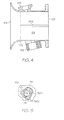
- FIG. 4 is a cross-sectional view of an exemplary valve body that is used to construct the valve assembly of FIGS. 1-3;
- an exemplary embodiment of an outflow valve 100 that may be used to control aircraft cabin pressure is shown and includes a valve body 102, a sleeve 104, a valve element 106, and a plurality of brackets 108.
- the valve body 102 includes an outer surface 112, and an inner surface 114 that defines a flow passage 116 having at least a first flow port 118, a second flow port 122.
- the valve body 102 is preferably adapted to mount to an aircraft fuselage (not shown), such that the first flow port 118 is in fluid communication with the aircraft cabin and the second flow port 122 is in fluid communication with the ambient environment outside the fuselage.
- the valve body 102 may be constructed of any one of numerous molded plastic/composite materials including, for example, fiber-reinforced polyetherimide (PEI), fiber-reinforced polyetheretherketon (PEEK), or any one of numerous other moldable composite materials.
- PEI fiber-reinforced polyetherimide
- PEEK fiber-reinforced polyetheretherketon
- the valve body 102 is preferably molded such that the first flow port 116 is a bell-shape, which is a shape that increases air speed and reduces total pressure drop.
- the valve body 102 is also molded to include a mount flange 124 proximate the valve body second flow port 122.
- the mount flange 124 extends radially outwardly from the valve body 102, and includes a plurality of evenly spaced fastener openings 126.
- a norl-illustrated fastener extends through each of these openings 126 to mount the valve body 102 to a non-illustrated aircraft bulkhead.
- the valve body 102 is also preferably molded to include, among other things, an actuator mount surface 128, and a valve closure and rotational stop mechanism housing 132.
- the sleeve 104 is disposed within the valve body flow passage 116 and has a flow passage 134 formed therein that is in fluid communication with the valve body first and second flow ports 118, 122.
- the valve 100 is implemented with a dual-wall flow passage, in which the sleeve 104 serves as one wall, and at least a portion of the valve body inner surface 114 serves as another wall.
- the sleeve 104 is disposed within the valve body flow passage 116 after the valve body 102 has been molded, and is bonded to valve body inner surface 114 using a suitable adhesive. In this regard, and as shown most clearly in FIG.
- the valve body 102 is preferably molded to include a plurality of ribs 402 on at least a portion of its inner surface 114.
- the ribs 402 only one of which is shown in FIG. 4, extend radially inwardly a predetermined distance and are used to locate the sleeve 104 within the valve body flow passage 116.
- the valve body 102 may, in alternative embodiments, be implemented without the ribs 402. In either case, however, it is preferable that the bond between the sleeve 104 and the valve body inner surface 114 does not fuse the sleeve 104 to the valve housing inner surface 114 or form a single walled element.
- the bond is formed such that the dual-wall flow passage configuration is maintained, which provides various advantages including, for example, redundancy.
- the sleeve 104 is preferably constructed at least partially of a metallic material. Although any one of numerous suitable materials may be used, in a particular preferred embodiment the sleeve is constructed of aluminum, or at least partially of aluminum.
- the valve element 106 is rotationally disposed within the sleeve flow passage 134 and is configured to rotate through a plurality of positions, from a fully open position to a fully closed position, to thereby control cabin pressure in the aircraft cabin into which it is installed.
- the valve element 106 may be variously configured to provide this functionality, in the depicted embodiment, it is configured as a butterfly plate assembly that includes a butterfly plate 136, a wiper seal 138, and a reinforcing ring 142, which are coupled together via a plurality of fasteners 144.
- the butterfly plate 136 may be constructed of a suitable plastic/composite material or metal that is molded to a desired geometry and with suitable interface features.
- Some suitable exemplary construction materials include fiber-reinforced PEI, fiber-reinforced PEEK, or aluminum.
- suitable interface features with which the butterfly plate 136 is preferably molded include, but are not limited to, a mounting interface for the reinforcing ring 142, and a shaft sleeve 146 that preferably extends through the butterfly plate 136 at an angle.
- the wiper seal 138 is a flat annular ring made of, for example, dacron reinforced silicon material, and is disposed between the butterfly plate 136 and the reinforcing ring 142. It will be appreciated that this material and shape are merely exemplary, and that the wiper seal 138 could be constructed of any one of numerous other suitable materials and have any one of numerous other suitable shapes.
- the reinforcing ring 142 is preferably manufactured from steel, but could be formed of any one of numerous other suitable materials.
- valve element 106 is rotationally disposed within the sleeve flow passage 134 via a shaft 148. More specifically, the shaft 148 is rotationally mounted on the valve body 102 via first and second shaft reinforcement sleeves 152, 154, and extends through valve element 106 via the shaft sleeve 146.
- the shaft reinforcement sleeves 152, 154 in addition to providing reinforcement to the shaft 148, also preferably function as bearings. As such, the shaft reinforcement sleeves 152, 154 are preferably implemented with appropriate friction and wear properties.
- the shaft reinforcement sleeves 152, 154 do not function as bearings, and instead suitable ball bearings are included in the valve 100.
- the shaft reinforcement sleeves 152, 154 may be press fit onto, or tolerance fit over, the shaft 148.
- the shaft 148 is preferably coupled to the butterfly plate 136 via a plurality of valve element mount fasteners 156. It will be appreciated, however, that the butterfly plate 136 could instead include an internal serration, or other means, to mate with the shaft 148. Moreover, although the shaft 148 is depicted as being constructed as a single shaft, it will be appreciated that it could also be constructed of two or more shafts. No matter the specific construction of the shaft 148, a first end 158 thereof preferably includes an actuator interface 162, such as the depicted slot, that is configured to mate with a non-illustrated valve actuator.
- the actuator which may be an electromechanical, pneumatic, or hydraulic type of actuator, is used to supply a drive force to the shaft 148 to move the valve element 106 to a desired position.
- the second end 164 of the shaft 148 is configured to mate with a valve closure and rotational stop mechanism 170, a preferred embodiment of which will now be described.
- the valve closure and rotational stop mechanism 170 is disposed within the valve closure and rotational stop mechanism housing 132 and is enclosed therein via a cover plate 166 and suitable fasteners 168.
- the valve closure and rotational stop mechanism 170 includes a torsion spring 172 and a shaft boss 174.
- the torsion spring 172 surrounds the shaft second end 164 and is coupled between the valve closure and rotational stop mechanism housing 132 and the shaft boss 174.
- the torsion spring 172 is configured to supply a bias torque to the shaft 148 that biases the valve element 106 toward the fully closed position.
- the torsion spring 172 is implemented as a coil spring. It will be appreciated, however, that the torsion spring 172 could alternatively be implemented using any one of numerous other types of springs including, for example, a leaf spring, a lever spring, a power spring, or a compression spring.
- the shaft boss 174 is mounted on the shaft second end 164 and, as shown most clearly in FIG. 5, includes a stop surface 502 that protrudes therefrom.
- the stop surface 502 is configured to selectively engage an end-of-travel stop 504 that, at least in the depicted embodiment, is integrally formed as part of the valve closure and rotational stop mechanism housing 132.
- the stop surface 502 engages the end-of-travel stop 504 when the valve element 106 is moved to its fully closed position.
- brackets 108 are evenly spaced around the valve body outer surface 112 and are each coupled to the inner sleeve 104 via a fastener 182.
- fastener 182 is a rivet 182.
- each of the brackets 108 includes a rivet opening 196
- the valve body 102 and inner sleeve 104 each include a plurality of rivet openings 186 and 188, respectively.
- the number of valve housing and inner sleeve rivet openings 186 and 188 may vary, in the depicted embodiment the valve body 102 and sleeve 104 both include four evenly spaced rivet openings 186 and 188.
- the valve body 102 is preferably molded to include four of the previously mentioned ribs 402 on its inner surface 114, and that each of the valve housing rivet openings 186 extends through one of the ribs 402, so that the fasteners 182 extend through the ribs 402.
- each bracket 108 in addition to being coupled to the inner sleeve 104, are also configured to be coupled to the non-illustrated aircraft bulkhead. More specifically, each bracket 108, at least in the depicted embodiment, is configured as an L-bracket 108 having a first section 192, and a second section 194 that is coupled to, and disposed substantially perpendicular to, the first section 192.
- the first section 192 is mounted on the valve body 102 and includes a rivet opening 196 (see FIG. 3).
- a plurality of flats one per bracket 108) is formed on the valve body outer surface 112.
- the second section 194 is disposed proximate the mount flange 124 and includes a mounting fastener opening 198 (also see FIG. 3).
- the mounting fastener openings 198 are each preferably collocated with one of the mount flange fastener openings 126. Therefore, although not illustrated, the brackets 108 couple the inner sleeve 104 to the aircraft fuselage via the mount flange fastener openings 126 in multiple places around the perimeter of the second flow port 122.
- the outflow valve assembly 100 described herein is relatively compact and lightweight, and is fairly simple to design and construct.
- the valve assembly includes suitable redundancy features that allow the valve assembly 100 to meet regulatory requirements for certain postulated single point failures.
Landscapes
- Engineering & Computer Science (AREA)
- General Engineering & Computer Science (AREA)
- Mechanical Engineering (AREA)
- Health & Medical Sciences (AREA)
- General Health & Medical Sciences (AREA)
- Pulmonology (AREA)
- Aviation & Aerospace Engineering (AREA)
- Lift Valve (AREA)
- Valve Housings (AREA)
Applications Claiming Priority (1)
| Application Number | Priority Date | Filing Date | Title |
|---|---|---|---|
| US11/369,344 US7472885B2 (en) | 2006-03-06 | 2006-03-06 | Compact, lightweight cabin pressure control system butterfly outflow valve with redundancy features |
Publications (2)
| Publication Number | Publication Date |
|---|---|
| EP1832512A2 true EP1832512A2 (fr) | 2007-09-12 |
| EP1832512A3 EP1832512A3 (fr) | 2009-03-04 |
Family
ID=38093084
Family Applications (1)
| Application Number | Title | Priority Date | Filing Date |
|---|---|---|---|
| EP07103552A Withdrawn EP1832512A3 (fr) | 2006-03-06 | 2007-03-06 | Vanne d'échappement à papillon de circuit de régulation de pression de cabine compacte, légère avec des caractéristiques de redondance |
Country Status (2)
| Country | Link |
|---|---|
| US (1) | US7472885B2 (fr) |
| EP (1) | EP1832512A3 (fr) |
Cited By (1)
| Publication number | Priority date | Publication date | Assignee | Title |
|---|---|---|---|---|
| WO2019092189A1 (fr) * | 2017-11-09 | 2019-05-16 | Eaton Intelligent Power Limited | Clapet à bille |
Families Citing this family (5)
| Publication number | Priority date | Publication date | Assignee | Title |
|---|---|---|---|---|
| US20080197236A1 (en) | 2007-02-15 | 2008-08-21 | Honeywell International Inc. | Lightweight composite material and metal thrust recovery flapper valve |
| US8347908B2 (en) * | 2009-08-27 | 2013-01-08 | Honeywell International Inc. | Lightweight titanium aluminide valves and methods for the manufacture thereof |
| GB201020504D0 (en) * | 2010-12-03 | 2011-01-19 | Magma Global Ltd | Pipe system |
| US9334972B2 (en) | 2014-05-15 | 2016-05-10 | Honeywell International Inc. | Composite injection molded check valve with integrated features |
| FR3032253B1 (fr) * | 2015-02-04 | 2017-01-20 | Mmt Sa | Vanne electro-commandee pour fluide chaud |
Citations (2)
| Publication number | Priority date | Publication date | Assignee | Title |
|---|---|---|---|---|
| EP0485076A1 (fr) | 1990-11-08 | 1992-05-13 | British Gas plc | Garniture |
| US6352241B1 (en) | 1998-11-26 | 2002-03-05 | Mannesmann Vdo Ag | Butterfly valve body |
Family Cites Families (16)
| Publication number | Priority date | Publication date | Assignee | Title |
|---|---|---|---|---|
| US2846934A (en) * | 1953-08-10 | 1958-08-12 | Garrett Corp | Cabin pressure outflow valve |
| US2830521A (en) * | 1955-03-01 | 1958-04-15 | Garrett Corp | Cabin pressure outflow valve |
| US3142502A (en) * | 1960-07-01 | 1964-07-28 | Anchor Coupling Co Inc | Longitudinally split hose clamp coupling having extrusion reducing ribs |
| AT339107B (de) * | 1974-03-12 | 1977-10-10 | Huebner Vamag | Abdichtung fur absperrklappen |
| US4777977A (en) * | 1984-12-31 | 1988-10-18 | Itt Corporation | Composite butterfly valve housing |
| FR2621377B1 (fr) * | 1987-10-02 | 1989-12-01 | Abg Semca | Segment d'etancheite pour vanne a papillon |
| GB9208069D0 (en) * | 1992-04-03 | 1992-05-27 | Turboflex Ltd | Coupling |
| FR2762374B1 (fr) * | 1997-04-18 | 1999-06-04 | Coutier Moulage Gen Ind | Vanne papillon pour la regulation du debit d'un fluide et ses procedes de fabrication |
| US5971026A (en) * | 1997-12-09 | 1999-10-26 | Honeywell Inc. | Internal geometry shape design for venturi tube-like gas-air mixing valve |
| DE19932956B4 (de) * | 1998-07-15 | 2009-04-09 | Toyoda Gosei Co., Ltd. | Schlauchverbindung |
| US6764062B1 (en) * | 1999-06-29 | 2004-07-20 | Siemens Vdo Automotive, Inc. | Plastic throttle body |
| DE10007611A1 (de) * | 2000-02-18 | 2001-08-23 | Mannesmann Vdo Ag | Drosselklappenstutzen |
| DE10044294A1 (de) * | 2000-09-07 | 2002-05-16 | Siemens Ag | Drosselklappenstutzen |
| US6589380B2 (en) * | 2001-02-07 | 2003-07-08 | Delphi Technologies, Inc. | Laser welded air control valve and method |
| DE10138931A1 (de) * | 2001-08-08 | 2003-03-06 | Bosch Gmbh Robert | Drosselvorrichtungsgehäuse mit flexiblen Ausgleichselementen für Brennkraftmaschinen |
| US6783114B2 (en) * | 2001-12-11 | 2004-08-31 | Honeywell International, Inc. | Cable assembly and air outflow valve incorporating the same |
-
2006
- 2006-03-06 US US11/369,344 patent/US7472885B2/en active Active
-
2007
- 2007-03-06 EP EP07103552A patent/EP1832512A3/fr not_active Withdrawn
Patent Citations (2)
| Publication number | Priority date | Publication date | Assignee | Title |
|---|---|---|---|---|
| EP0485076A1 (fr) | 1990-11-08 | 1992-05-13 | British Gas plc | Garniture |
| US6352241B1 (en) | 1998-11-26 | 2002-03-05 | Mannesmann Vdo Ag | Butterfly valve body |
Cited By (1)
| Publication number | Priority date | Publication date | Assignee | Title |
|---|---|---|---|---|
| WO2019092189A1 (fr) * | 2017-11-09 | 2019-05-16 | Eaton Intelligent Power Limited | Clapet à bille |
Also Published As
| Publication number | Publication date |
|---|---|
| EP1832512A3 (fr) | 2009-03-04 |
| US20070205386A1 (en) | 2007-09-06 |
| US7472885B2 (en) | 2009-01-06 |
Similar Documents
| Publication | Publication Date | Title |
|---|---|---|
| US7571742B2 (en) | Butterfly outflow valve | |
| EP1832512A2 (fr) | Vanne d'échappement à papillon de circuit de régulation de pression de cabine compacte, légère avec des caractéristiques de redondance | |
| US9096320B2 (en) | Cabin pressure thrust recovery outflow valve with single door | |
| US7325569B2 (en) | Butterfly valve with integral split flapper relief valve | |
| EP1618038B1 (fr) | Soupape entierement integree pour systeme de regulation de la pression de la cabine d'un avion | |
| JP5368452B2 (ja) | 航空機用流出弁 | |
| US9234672B2 (en) | Lightweight cabin pressure thrust recovery outflow valve | |
| EP1847458A2 (fr) | Ensemble de porte à entrée d'air de diffusion | |
| US20100096503A1 (en) | Outflow valve having j-shaped bellmouth and cabin pressure control system employing the same | |
| US20090023381A1 (en) | Integrated housing for fan and alternate flow check valve | |
| EP1610606A1 (fr) | Vanne à clapet pivotant sans articulation pour la régulation du débit | |
| US20100190428A1 (en) | Thrust recovery, or other valve, containing two independently actuated doors and control system | |
| US7334773B2 (en) | Outflow valve having a cable operated closure mechanism | |
| US9481469B2 (en) | Valve for controlling the internal pressure in a cabin of an aircraft | |
| US20100240291A1 (en) | Outflow valve position indication | |
| US10408218B2 (en) | Fan with shut-off valve and method of operating | |
| US20130118624A1 (en) | Sealed flapper diverter valve | |
| US6962324B2 (en) | Cabin pressure outflow control valve having non-linear flow control characteristics | |
| US20100193643A1 (en) | Lift fan system | |
| US7694937B2 (en) | Outflow valve | |
| US8382035B2 (en) | Poppet valve for cabin pressure control systems | |
| EP1958874A2 (fr) | Vanne à clapet léger de récupération de poussée en matériau composite et métal | |
| US20100019184A1 (en) | Valve seal with integral flexure joints | |
| US20030107019A1 (en) | Cable assembly and air outflow valve incorporating the same | |
| CN210118500U (zh) | 压力控制装置 |
Legal Events
| Date | Code | Title | Description |
|---|---|---|---|
| PUAI | Public reference made under article 153(3) epc to a published international application that has entered the european phase |
Free format text: ORIGINAL CODE: 0009012 |
|
| AK | Designated contracting states |
Kind code of ref document: A2 Designated state(s): AT BE BG CH CY CZ DE DK EE ES FI FR GB GR HU IE IS IT LI LT LU LV MC MT NL PL PT RO SE SI SK TR |
|
| AX | Request for extension of the european patent |
Extension state: AL BA HR MK YU |
|
| PUAL | Search report despatched |
Free format text: ORIGINAL CODE: 0009013 |
|
| AK | Designated contracting states |
Kind code of ref document: A3 Designated state(s): AT BE BG CH CY CZ DE DK EE ES FI FR GB GR HU IE IS IT LI LT LU LV MC MT NL PL PT RO SE SI SK TR |
|
| AX | Request for extension of the european patent |
Extension state: AL BA HR MK RS |
|
| 17Q | First examination report despatched |
Effective date: 20090923 |
|
| 17P | Request for examination filed |
Effective date: 20090824 |
|
| AKX | Designation fees paid |
Designated state(s): DE FR |
|
| GRAP | Despatch of communication of intention to grant a patent |
Free format text: ORIGINAL CODE: EPIDOSNIGR1 |
|
| STAA | Information on the status of an ep patent application or granted ep patent |
Free format text: STATUS: THE APPLICATION IS DEEMED TO BE WITHDRAWN |
|
| 18D | Application deemed to be withdrawn |
Effective date: 20110209 |