EP1832549B1 - Zapfsäule mit Schlauchrückführung - Google Patents
Zapfsäule mit Schlauchrückführung Download PDFInfo
- Publication number
- EP1832549B1 EP1832549B1 EP07103175A EP07103175A EP1832549B1 EP 1832549 B1 EP1832549 B1 EP 1832549B1 EP 07103175 A EP07103175 A EP 07103175A EP 07103175 A EP07103175 A EP 07103175A EP 1832549 B1 EP1832549 B1 EP 1832549B1
- Authority
- EP
- European Patent Office
- Prior art keywords
- hose
- dispenser
- housing
- rollers
- cord
- Prior art date
- Legal status (The legal status is an assumption and is not a legal conclusion. Google has not performed a legal analysis and makes no representation as to the accuracy of the status listed.)
- Ceased
Links
Images



Classifications
-
- B—PERFORMING OPERATIONS; TRANSPORTING
- B67—OPENING, CLOSING OR CLEANING BOTTLES, JARS OR SIMILAR CONTAINERS; LIQUID HANDLING
- B67D—DISPENSING, DELIVERING OR TRANSFERRING LIQUIDS, NOT OTHERWISE PROVIDED FOR
- B67D7/00—Apparatus or devices for transferring liquids from bulk storage containers or reservoirs into vehicles or into portable containers, e.g. for retail sale purposes
- B67D7/06—Details or accessories
- B67D7/38—Arrangements of hoses, e.g. operative connection with pump motor
- B67D7/40—Suspending, reeling or storing devices
-
- B—PERFORMING OPERATIONS; TRANSPORTING
- B67—OPENING, CLOSING OR CLEANING BOTTLES, JARS OR SIMILAR CONTAINERS; LIQUID HANDLING
- B67D—DISPENSING, DELIVERING OR TRANSFERRING LIQUIDS, NOT OTHERWISE PROVIDED FOR
- B67D7/00—Apparatus or devices for transferring liquids from bulk storage containers or reservoirs into vehicles or into portable containers, e.g. for retail sale purposes
- B67D7/04—Apparatus or devices for transferring liquids from bulk storage containers or reservoirs into vehicles or into portable containers, e.g. for retail sale purposes for transferring fuels, lubricants or mixed fuels and lubricants
Definitions
- the present invention relates to a hose retraction mechanism of a fuel dispenser.
- the simplest type of hose arrangement for a fuel dispenser comprises a hose external to the fuel dispenser, which hose is hung from an outlet line high up on the fuel dispenser, whereby the hose is then simply supported by being attached at one end to the outlet line and at its other end to a nozzle which, in a rest position, is supported by a cradle in the dispenser.
- dispensers also exist whereby a length of hose is contained within the housing of a fuel dispenser, as illustrated in the prior art examples of Figures 1 and 2 attached hereto, and in UK Patent GB. 1 217 420 , European Patent Application EP 1 253 106 , which corresponds to the preamble of claim 1, and International Patent Application WO 00/61490 .
- a hose is supported by an upper portion of the housing within the dispenser and by the nozzle supported in the cradle, as shown.
- the hose passes through a slot in the housing which slot extends from slightly below the nozzle cradle, to just above the ground, such that in use the hose can swing out of housing as the nozzle is pulled away from the dispenser by a user.
- This arrangement however, there is only a limited length of hose that can be accommodated within the housing, otherwise an excessive amount of hose will protrude from the housing when the nozzle is resting on its cradle, which is both unsightly and could also present a potential hazard.
- retractor mechanisms are also known, one of which is illustrated in Figure 2 .
- the retractor mechanism of Figure 2 comprises a fixed upper roller which the hose is looped over and a lower, weighted, roller under which the hose passes. Gravity acting on the lower roller causes the hose to be retracted into the housing as the lower roller sinks to the bottom of the housing.
- this arrangement permits a greater length of hose to be available than in the Figure 1 arrangement, the cost of producing a hose retractor arrangement as shown is relatively expensive, for it requires additional panels to be included within the dispenser as the lower roller has to be sandwiched between two closely spaced panels. The hose then traverses one of the panels as it passes over the upper roller such that the hose extending between the upper roller and nozzle is contained within a second compartment adjacent to the first compartment in which the lower roller is housed.
- a further problem with the arrangement in Figure 2 is that the weighted roller has to be sufficiently heavy to ensure the hose will be reliably retracted throughout the lifetime of the dispenser, regardless of the stiffness of the hose which is both dependent on temperature and material, and thus a significant pull force is required. This is acceptable where a car is being fuelled from a side adjacent the dispenser, for there will normally be a sufficient length of free hose to fuel the car without movement of the weighted pulley, or the hose may be pulled in a straight line to the filler cap of the vehicle.
- a fuel dispenser having a housing, a nozzle for dispensing fuel, a fuel delivery hose connecting the nozzle to a main body of the dispenser and a hose retraction mechanism for retracting the hose into the housing of the dispenser through an aperture in the housing
- the hose retractor mechanism including a cord, means for attaching the cord to a connection point on the hose remote from the ends of the hose, biasing means for retracting the cord so as to urge the connection point on the hose to a high point in an upper portion of the housing and two rollers located adjacent the aperture, the hose running below the two rollers and passing through the aperture out of the housing, wherein the two rollers arranged sequentially such that the two rollers act together to first guide a section of hose and then a section of cord as the hose is drawn from the housing out through the aperture, a first one of the rollers being arranged to receive the hose when it is retracted into the housing and a second one of the rollers located further from the aperture than
- An arrangement in accordance with the present invention permits a relatively long length of hose to be contained within the housing of a dispenser with the hose normally being accommodate within a single compartment.
- This arrangement permits the hose to be pulled out of the dispenser with negligible resistive force, thus the only force that needs to be overcome to withdraw the hose is the force exerted by the biasing means for retracting the cord.
- This can be set at a fairly low value, requiring to only slightly greater than that sufficient to reliably lift the weight of the hose to the top of the cabinet.
- a significant reduction in the required pull force is achieved mechanism is particularly smooth compared to the prior art arrangement illustrated in Figure 2 .
- Cabinet design is also simplified compared to the prior art arrangement illustrated in Figure 2 .
- the two rollers adjacent the aperture can smoothly guide the hose and cord, when the hose is pulled from the fuel dispenser housing and permits the retraction mechanism to have a relatively smooth action despite the angles through which the hose must necessarily be bent to permit the hose to be retracted to the top of the housing.
- two rollers are located at about waist level of a user, whereby when the nozzle and hose are drawn out of the dispenser, as in normal use, the hose between the nozzle and the first roller will define a first line extending generally in a horizontal direction, the second roller and the high point defining a second line inclined at an angle relative to the first line, with the axes of rotation of the rollers being substantially parallel and horizontal lying on a plane such that the third line perpendicular to the plane of the rollers subtends angles B and C equal to half of angle A ⁇ 10° relative to the first line and second line, respectively.
- angles B and C are equal to half that of angle A ⁇ 5°.
- the dispenser further comprises a cradle for the nozzle, the cradle being mounted above the aperture, wherein the aperture extends substantially to ground level to form a vertical slot through which the hose may pass, wherein the end of the hose remote from the nozzle is connected to the dispenser within the housing towards the top of the housing on the opposite side to that of the aperture, with said high point being located substantially midway between the front of the housing in which the aperture is located and the back of the housing towards which the hose is connected to the dispenser, with the connection point with the cord on the hose being towards a central portion of the hose, wherein the hose, when fully retracted, is arranged to hang in a W shape.
- the dispenser is arranged such that when the nozzle is first lifted from the cradle and withdrawn from the dispenser, the hose will be drawn into contact with the two rollers, further withdrawal drawing the cord into contact with the rollers whereupon the cord is guided out of the housing by said rollers.
- This permits the rollers to guide both the hose during the first part of the process to withdraw and to guide the cord during a second further part of the withdrawal process.
- both rollers are profiled to centrally guide both the cord and the hose.
- the dispenser preferably further comprises a hose clamp for connecting the cord to the hose at the connection point on the hose, the hose clamp being clamped on the hose with the cord located on the clamp towards the end of the clamp proximal to the nozzle.
- the cord being attached towards the front of the clamp greatly assists the smooth operation of the retraction mechanism as the clamp is retracted past the rollers.
- the surface of the clamp has protrusions for engaging with the surface of the hose, the protrusions being elongate and extending in a direction having a component along the axis of the hose to resist rotation of the hose about its axis within the clamp.
- Protrusions having a zigzag shape extending in the axial direction of the clamp have been found to be particularly advantageous.
- a fuel dispenser indicated generally as 1, having a volume display 2, a price display 3 and a housing 4, a lower portion 4a of which houses the hydraulic equipment associated with the fuel dispenser and an end portion 4b of which provides a housing for six hoses (three on each side) together with their associated cord retraction mechanisms.
- FIG 4 an end view along the line IV-IV of Figure 3a (with the end panel removed) there is shown the components of a hose retraction system for hose 5 and associated nozzle 6.
- the nozzle 6 rests in cradle 7 associated with that nozzle.
- the nozzle 6 is connected by hose 5 to an outlet of the dispenser 8 from which the hose 5 receives fuel to be dispensed by the dispenser.
- a hose clamp 9 is affixed to the hose at a point 1.7 to 2.0 m along the hose from the outlet 8, to ensure the hose, when fully retracted hangs so that the section of hose between the clamp and the nozzle hangs substantially in a U-shape when the nozzle is in its cradle and so that the section of hose between the clamp 9 and outlet 8 remains suspended throughout the retraction cycle.
- the clamp 9 is supported by a cord 10 which is wrapped around spring loaded drum 11 which drum acts to bias the clamp 9 to the top of the housing, such that the clamp and associated portion of the hose are suspended from the top of the housing, as illustrated in Figure 4 .
- the spring loaded drum typically exerts a force of 45 to 50 N, sufficient to ensure the hose when full can be reliably retracted (lifted) to the position shown.
- the hose extends to a bottom portion of the housing where it passes through aperture 12 (a corresponding aperture being shown more clearly in Figure 3a ) to the outside of the dispenser. Here it is supported by being connected at the end 13 to the nozzle 6.
- first roller 14 and a second roller 15 shown in side elevation in Figure 4 and in front elevation in Figure 3b, Figure 3b being an enlarged view of the section indicated in Figure 3a with the housing removed.
- the hose adopts a substantially "W"-shape, with a panel 16 separating adjacent hoses into separate compartments, each compartment being only slightly wider than the width of the hose, to prevent the hose 5 passing by itself and potentially jamming on itself.
- the second roller 15 is the only roller in contact with the hose 5 and the roller 15 maintains the hose within the housing such that the hose hangs neatly, substantially vertically, from the nozzle (instead of extending away from the dispenser which could occur if the hose was not retained in position by the roller 15).
- a first line X has been drawn which extends generally in the direction of the hose and the cord outside of the dispenser when the hose is pulled from the dispenser in normal operation.
- This line X subtends a first angle A relative to the cord extending between the roller 15 and the drum 11, represented as line Y. It is has been found that if the rollers 14 and 15 are arranged with their axes of rotation parallel, substantially horizontal and lying on a plane perpendicular to the line Z, which line Z subtends angles B and C equal to half the angle A, then this results in a hose retraction system having a particularly smooth retraction properties, particularly as the clamp 9 passes across the rollers.
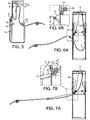
- the clamp 9 is shown in more detail in Figures 8 to 10 .
- the clamp is seen to comprise a top portion 9a and a bottom portion 9b screwed together to clamp the hose (not shown) therebetween.
- the top portion 9a has a hole 17, through which the cord extends.
- the cord is knotted on the far side of the aperture to thereby secure the cord to the clamp 9.
- the hole 17 is located towards one end of the clamp 9 and, as can be seen from Figure 6b , the cord is thus secured towards the nozzle end 8.
- This arrangement has been found to be particularly advantageous in that, as most clearly can be seen from Figure 6a , it encourages the hose 5 between the clamp 9 and dispenser outlet 8 to drop towards the floor of the dispenser.
Landscapes
- Engineering & Computer Science (AREA)
- Mechanical Engineering (AREA)
- Loading And Unloading Of Fuel Tanks Or Ships (AREA)
Claims (9)
- Zapfsäule (1), die ein Gehäuse (4), eine Zapfpistole (6) zur Kraftstoffausgabe, einen Kraftstoffdruckschlauch (5), der die Zapfpistole mit dem Hauptkörper der Zapfsäule verbindet und eine Schlauchrückführung zum Rückführen des Schlauchs in das Gehäuse der Zapfsäule durch eine Öffnung (12) im Gehäuse umfasst, wobei die Schlauchrückführung weiter eine Schnur (10), Mittel (9) zum Anbringen der Schnur an einen Verbindungspunkt am Schlauch fern von den Schlauchenden, Vorspannmittel (11) zum Rückführen der Schnur einschließt, um den Verbindungspunkt am Schlauch an eine hohe Stelle im oberen Abschnitt des Gehäuses drängen, wobei die Zapfsäule weiter zwei Rollen (14, 15) umfasst, die sich angrenzend an die Öffnung befinden, dadurch gekennzeichnet, dass der Schlauch unterhalb der zwei Rollen läuft und, wenn in der rückgeführten Position befindlich, durch die Öffnung aus dem Gehäuse läuft, wobei, die zwei Rollen sequenziell so angeordnet sind, dass sie zusammenarbeiten, um zuerst einen Teil des Schlauchs (5) und danach einen Abschnitt der besagten Schnur (10) zu führen, sowie der Schlauch durch die Öffnung aus dem Gehäuse gezogen wird, wobei eine Erste (14) der Rollen angeordnet ist den Schlauch aufzunehmen, wenn er in das Gehäuse rückgeführt wird und eine Zweite (15) der Rollen weiter weg von der Öffnung als die erste Rolle und höher als die erste Rolle positioniert ist, um den Schlauch in Richtung des hohen Punkts zu führen.
- Zapfsäule nach Anspruch 1, wobei sich die zwei Rollen auf etwa Hüfthöhe eines Benutzers befinden, sodass, wenn die Zapfpistole und der Schlauch bei normaler Verwendung von einem Benutzer aus der Zapfsäule gezogen werden, der Schlauch zwischen der Zapfpistole und der ersten Rolle eine erste Linie (X) definieren wird, die sich generell in horizontaler Richtung erstreckt, wobei die zweite Rolle und der hohe Punkt eine zweite Linie (Y) definieren, die in einen Winkel relativ zur ersten Linie geneigt ist, wobei die Rotationsachsen der Rollen im Wesentlichen parallel sind und horizontal so auf einer Ebene liegen, dass die dritte Linie (Z) senkrecht zur Ebene der Rollen den Winkeln B und C gleich dem halben Winkel A ± 10° relativ zur ersten bzw. zweiten Linie gegenüberliegt.
- Zapfsäule nach Anspruch 2, wobei Winkel B und C gleich der Hälfte des Winkels A ± 5°.
- Zapfsäule nach einem vorhergehenden Anspruch, die weiter eine Wiege (7) für die Zapfpistole (6) umfasst, wobei die Wiege oberhalb der Öffnung (12) montiert ist, wobei sich die Öffnung (12) im Wesentlichen auf Bodenhöhe erstreckt, um einen vertikalen Schlitz zu bilden, durch den der Schlauch passieren könnte, wobei das von der Zapfpistole ferne Ende des Schlauchs mit dem Hauptkörper der Zapfsäule innerhalb des Gehäuses in Richtung der Oberseite des Gehäuses auf der entgegengesetzten Seite zu jener der Öffnung verbunden ist, wobei besagter hohe Punkt im Wesentlichen auf halbem Weg zwischen der Vorderseite des Gehäuses, in der sich die Öffnung befindet und der Rückseite des Gehäuses in dessen Richtung der Schlauch an die Zapfsäule angeschlossen ist, wobei der Verbindungspunkt mit der Schnur am Schlauch in einem zentralen Teil des Schlauchs liegt, wobei der Schlauch, wenn voll rückgeführt, angeordnet ist in einer W-Form zu hängen.
- Zapfsäule nach Anspruch 4, die so eingerichtet ist, dass, wenn die Zapfpistole zuerst aus der Wiege gehoben und aus der Zapfsäule herausgezogen wird, der Schlauch in Kontakt mit zwei Rollen (14, 15) gezogen wird, wobei weiteres Herausziehen die Schnur in Kontakt mit den zwei Rollen zieht, wonach die Schnur durch besagte Rollen aus dem Gehäuse geführt wird.
- Zapfsäule nach einem vorhergehenden Anspruch, wobei beide Rollen (14, 15) profiliert sind, um sowohl die Schnur als auch den Schlauch zentral zu führen.
- Zapfsäule nach einem vorhergehenden Anspruch, die weiter eine Schlauchschelle (9) zum Verbinden der Schnur mit dem Schlauch am Verbindungspunkt umfasst und die Schlauchschelle an den Schlauch geklemmt wird, wobei sich die Schnur an der Schelle Richtung des Schellenendes proximal der Zapfpistole befindet.
- Zapfsäule nach Anspruch 7, wobei eine Innenfläche der Schelle Vorsprünge (18) zum Eingreifen in die Oberfläche des Schlauchs aufweist, wobei die Vorsprünge länglich sind und sich in einer Richtung erstrecken, die eine Komponente entlang der Schlauchachse aufweist, um Rotation des Schlauchs um seine Achse innerhalb der Schelle zu widerstehen.
- Zapfsäule nach Anspruch 8, wobei die länglichen Vorsprünge (18) eine Zickzackform aufweisen, die sich in einer axialen Richtung der Schelle erstreckt.
Applications Claiming Priority (1)
| Application Number | Priority Date | Filing Date | Title |
|---|---|---|---|
| GB0604563A GB2435878A (en) | 2006-03-07 | 2006-03-07 | A Fuel Dispenser |
Publications (2)
| Publication Number | Publication Date |
|---|---|
| EP1832549A1 EP1832549A1 (de) | 2007-09-12 |
| EP1832549B1 true EP1832549B1 (de) | 2008-12-10 |
Family
ID=36241117
Family Applications (1)
| Application Number | Title | Priority Date | Filing Date |
|---|---|---|---|
| EP07103175A Ceased EP1832549B1 (de) | 2006-03-07 | 2007-02-27 | Zapfsäule mit Schlauchrückführung |
Country Status (3)
| Country | Link |
|---|---|
| EP (1) | EP1832549B1 (de) |
| DE (1) | DE602007000331D1 (de) |
| GB (1) | GB2435878A (de) |
Cited By (1)
| Publication number | Priority date | Publication date | Assignee | Title |
|---|---|---|---|---|
| RU242873U1 (ru) * | 2025-12-28 | 2026-04-15 | Общество с ограниченной ответственностью "Топаз-сервис" | Топливораздаточная колонка с механизмом возврата рукава |
Families Citing this family (3)
| Publication number | Priority date | Publication date | Assignee | Title |
|---|---|---|---|---|
| EP2871151A1 (de) * | 2013-11-08 | 2015-05-13 | Scheidt & Bachmann GmbH | Zapfschlauchanordnung |
| CN104860253A (zh) * | 2015-04-01 | 2015-08-26 | 江阴市富仁高科股份有限公司 | 一种l型下出管加油机 |
| CN110734032A (zh) * | 2019-09-29 | 2020-01-31 | 北京长吉加油设备有限公司 | 一种加油机的胶管回收枪柜及加油机 |
Family Cites Families (6)
| Publication number | Priority date | Publication date | Assignee | Title |
|---|---|---|---|---|
| GB1217420A (en) * | 1968-08-15 | 1970-12-31 | Rubery Owen Pumps Ltd | Improvements relating to petrol dispensing installations |
| ES2085810T3 (es) * | 1994-08-31 | 1996-06-01 | Scheidt & Bachmann Gmbh | Dispositivo de retorno de la manguera para surtidores de carburantes. |
| NL1010078C2 (nl) * | 1998-09-14 | 2000-03-15 | Koppens Automatic Fabrieken Bv | Slangbergingsinrichting. |
| US6199579B1 (en) * | 1999-04-14 | 2001-03-13 | Dresser Equipment Group, Inc. | Hose handling system and method |
| SE523449C2 (sv) * | 2001-03-22 | 2004-04-20 | Dresser Wayne Ab | Anordning samt förfarande för hantering av en slang samt bränslepumpsaggregat |
| SE518625C2 (sv) * | 2001-03-22 | 2002-10-29 | Dresser Wayne Ab | Anordning samt förfarande för hantering av en slang |
-
2006
- 2006-03-07 GB GB0604563A patent/GB2435878A/en not_active Withdrawn
-
2007
- 2007-02-27 DE DE602007000331T patent/DE602007000331D1/de active Active
- 2007-02-27 EP EP07103175A patent/EP1832549B1/de not_active Ceased
Cited By (1)
| Publication number | Priority date | Publication date | Assignee | Title |
|---|---|---|---|---|
| RU242873U1 (ru) * | 2025-12-28 | 2026-04-15 | Общество с ограниченной ответственностью "Топаз-сервис" | Топливораздаточная колонка с механизмом возврата рукава |
Also Published As
| Publication number | Publication date |
|---|---|
| DE602007000331D1 (de) | 2009-01-22 |
| GB0604563D0 (en) | 2006-04-19 |
| GB2435878A (en) | 2007-09-12 |
| EP1832549A1 (de) | 2007-09-12 |
Similar Documents
| Publication | Publication Date | Title |
|---|---|---|
| EP0836825B1 (de) | Blattspender mit Innenabzug | |
| CA2841383C (en) | Dispenser and stack of sheet products | |
| US9895033B2 (en) | Dispenser apparatus with damper for dispensing paper toweling | |
| EP1773168B1 (de) | Spender für aufgerolltes bogenmaterial | |
| AU2011263633A1 (en) | Paper roll dispenser comprising a base and at least one first door and one second door mounted on the base of the dispenser | |
| CN110775448B (zh) | 用于从薄巾卷分配连续的薄巾幅的部分的分配器和方法 | |
| US6062422A (en) | Paper roll dispenser | |
| CN201242412Y (zh) | 改进的测距装置 | |
| WO2016137364A1 (en) | Dispenser for a stack of web material | |
| EP1832549A1 (de) | Zapfsäule mit Schlauchrückführung | |
| US20130092701A1 (en) | Folded sheet dispenser with overfill prevention device | |
| KR102251335B1 (ko) | 옥내소화전용 자켓트 호스릴 장치 | |
| US20030122027A1 (en) | Dispenser | |
| US11963642B2 (en) | Dispenser insert for dispensing sheet products | |
| US20020145364A1 (en) | Towel loop formation in a hand towel dispenser | |
| KR102434328B1 (ko) | 롤형 제품 송급 시스템 | |
| CN211770275U (zh) | 一种加油机的胶管回收枪柜和胶管回收枪柜组及加油机 | |
| US7028945B2 (en) | Towel dispenser with tear bar | |
| KR100363501B1 (ko) | 급유장치 | |
| CN219584104U (zh) | 车辆 | |
| US20250162785A1 (en) | Bag Dispenser Assemby | |
| EP2253582B1 (de) | Brennstoffausgabeeinheit und Verfahren zur magnetischen Handhabung eines Schlauchs | |
| CN211871370U (zh) | 一种加油机的胶管回收枪柜及加油机 | |
| JP3536979B2 (ja) | 給油装置 | |
| EP2107037B1 (de) | Schlauchausleger für Zapfsäulen |
Legal Events
| Date | Code | Title | Description |
|---|---|---|---|
| PUAI | Public reference made under article 153(3) epc to a published international application that has entered the european phase |
Free format text: ORIGINAL CODE: 0009012 |
|
| AK | Designated contracting states |
Kind code of ref document: A1 Designated state(s): AT BE BG CH CY CZ DE DK EE ES FI FR GB GR HU IE IS IT LI LT LU LV MC NL PL PT RO SE SI SK TR |
|
| AX | Request for extension of the european patent |
Extension state: AL BA HR MK YU |
|
| 17P | Request for examination filed |
Effective date: 20080121 |
|
| 17Q | First examination report despatched |
Effective date: 20080218 |
|
| RAP1 | Party data changed (applicant data changed or rights of an application transferred) |
Owner name: DANAHER UK INDUSTRIES LTD. |
|
| AKX | Designation fees paid |
Designated state(s): DE GB |
|
| GRAP | Despatch of communication of intention to grant a patent |
Free format text: ORIGINAL CODE: EPIDOSNIGR1 |
|
| GRAS | Grant fee paid |
Free format text: ORIGINAL CODE: EPIDOSNIGR3 |
|
| GRAA | (expected) grant |
Free format text: ORIGINAL CODE: 0009210 |
|
| AK | Designated contracting states |
Kind code of ref document: B1 Designated state(s): DE GB |
|
| REG | Reference to a national code |
Ref country code: GB Ref legal event code: FG4D |
|
| REF | Corresponds to: |
Ref document number: 602007000331 Country of ref document: DE Date of ref document: 20090122 Kind code of ref document: P |
|
| PLBE | No opposition filed within time limit |
Free format text: ORIGINAL CODE: 0009261 |
|
| STAA | Information on the status of an ep patent application or granted ep patent |
Free format text: STATUS: NO OPPOSITION FILED WITHIN TIME LIMIT |
|
| 26N | No opposition filed |
Effective date: 20090911 |
|
| P01 | Opt-out of the competence of the unified patent court (upc) registered |
Effective date: 20230606 |
|
| PGFP | Annual fee paid to national office [announced via postgrant information from national office to epo] |
Ref country code: DE Payment date: 20240219 Year of fee payment: 18 Ref country code: GB Payment date: 20240219 Year of fee payment: 18 |
|
| REG | Reference to a national code |
Ref country code: DE Ref legal event code: R119 Ref document number: 602007000331 Country of ref document: DE |
|
| GBPC | Gb: european patent ceased through non-payment of renewal fee |
Effective date: 20250227 |
|
| PG25 | Lapsed in a contracting state [announced via postgrant information from national office to epo] |
Ref country code: DE Free format text: LAPSE BECAUSE OF NON-PAYMENT OF DUE FEES Effective date: 20250902 |
|
| PG25 | Lapsed in a contracting state [announced via postgrant information from national office to epo] |
Ref country code: GB Free format text: LAPSE BECAUSE OF NON-PAYMENT OF DUE FEES Effective date: 20250227 |