EP1832704A2 - Engrenage pour une fenêtre coulissante de véhicule automobile - Google Patents
Engrenage pour une fenêtre coulissante de véhicule automobile Download PDFInfo
- Publication number
- EP1832704A2 EP1832704A2 EP20070004262 EP07004262A EP1832704A2 EP 1832704 A2 EP1832704 A2 EP 1832704A2 EP 20070004262 EP20070004262 EP 20070004262 EP 07004262 A EP07004262 A EP 07004262A EP 1832704 A2 EP1832704 A2 EP 1832704A2
- Authority
- EP
- European Patent Office
- Prior art keywords
- window
- sliding
- movable
- sliding door
- reinforcement
- Prior art date
- Legal status (The legal status is an assumption and is not a legal conclusion. Google has not performed a legal analysis and makes no representation as to the accuracy of the status listed.)
- Withdrawn
Links
- 239000000463 material Substances 0.000 claims abstract description 27
- 239000004033 plastic Substances 0.000 claims abstract description 15
- 229920003023 plastic Polymers 0.000 claims abstract description 15
- 230000002787 reinforcement Effects 0.000 claims description 65
- 239000002184 metal Substances 0.000 claims description 8
- 238000005538 encapsulation Methods 0.000 claims description 6
- 229920002430 Fibre-reinforced plastic Polymers 0.000 claims description 2
- 238000010276 construction Methods 0.000 claims description 2
- 239000011151 fibre-reinforced plastic Substances 0.000 claims description 2
- 230000008901 benefit Effects 0.000 description 10
- 238000004519 manufacturing process Methods 0.000 description 9
- 238000011161 development Methods 0.000 description 7
- 230000018109 developmental process Effects 0.000 description 7
- 238000001746 injection moulding Methods 0.000 description 3
- 238000000034 method Methods 0.000 description 3
- 230000008859 change Effects 0.000 description 2
- 230000004048 modification Effects 0.000 description 2
- 238000012986 modification Methods 0.000 description 2
- 230000008569 process Effects 0.000 description 2
- 239000000243 solution Substances 0.000 description 2
- 230000007704 transition Effects 0.000 description 2
- 239000004696 Poly ether ether ketone Substances 0.000 description 1
- 229910000831 Steel Inorganic materials 0.000 description 1
- 230000002411 adverse Effects 0.000 description 1
- 230000003321 amplification Effects 0.000 description 1
- JUPQTSLXMOCDHR-UHFFFAOYSA-N benzene-1,4-diol;bis(4-fluorophenyl)methanone Chemical compound OC1=CC=C(O)C=C1.C1=CC(F)=CC=C1C(=O)C1=CC=C(F)C=C1 JUPQTSLXMOCDHR-UHFFFAOYSA-N 0.000 description 1
- 230000005540 biological transmission Effects 0.000 description 1
- 230000015572 biosynthetic process Effects 0.000 description 1
- 230000007423 decrease Effects 0.000 description 1
- 238000013461 design Methods 0.000 description 1
- 238000007765 extrusion coating Methods 0.000 description 1
- 238000002347 injection Methods 0.000 description 1
- 239000007924 injection Substances 0.000 description 1
- 230000007246 mechanism Effects 0.000 description 1
- 238000003801 milling Methods 0.000 description 1
- 238000002156 mixing Methods 0.000 description 1
- 238000003199 nucleic acid amplification method Methods 0.000 description 1
- 230000003287 optical effect Effects 0.000 description 1
- 229920002530 polyetherether ketone Polymers 0.000 description 1
- 239000012858 resilient material Substances 0.000 description 1
- 238000005096 rolling process Methods 0.000 description 1
- 239000007779 soft material Substances 0.000 description 1
- 125000006850 spacer group Chemical group 0.000 description 1
- 239000010421 standard material Substances 0.000 description 1
- 239000010959 steel Substances 0.000 description 1
- 238000012546 transfer Methods 0.000 description 1
Images

Classifications
-
- F—MECHANICAL ENGINEERING; LIGHTING; HEATING; WEAPONS; BLASTING
- F16—ENGINEERING ELEMENTS AND UNITS; GENERAL MEASURES FOR PRODUCING AND MAINTAINING EFFECTIVE FUNCTIONING OF MACHINES OR INSTALLATIONS; THERMAL INSULATION IN GENERAL
- F16H—GEARING
- F16H55/00—Elements with teeth or friction surfaces for conveying motion; Worms, pulleys or sheaves for gearing mechanisms
- F16H55/02—Toothed members; Worms
- F16H55/26—Racks
-
- E—FIXED CONSTRUCTIONS
- E05—LOCKS; KEYS; WINDOW OR DOOR FITTINGS; SAFES
- E05F—DEVICES FOR MOVING WINGS INTO OPEN OR CLOSED POSITION; CHECKS FOR WINGS; WING FITTINGS NOT OTHERWISE PROVIDED FOR, CONCERNED WITH THE FUNCTIONING OF THE WING
- E05F11/00—Man-operated mechanisms for operating wings, including those which also operate the fastening
- E05F11/38—Man-operated mechanisms for operating wings, including those which also operate the fastening for sliding windows, e.g. vehicle windows, to be opened or closed by vertical movement
- E05F11/42—Man-operated mechanisms for operating wings, including those which also operate the fastening for sliding windows, e.g. vehicle windows, to be opened or closed by vertical movement operated by rack bars and toothed wheels or other push-pull mechanisms
- E05F11/423—Man-operated mechanisms for operating wings, including those which also operate the fastening for sliding windows, e.g. vehicle windows, to be opened or closed by vertical movement operated by rack bars and toothed wheels or other push-pull mechanisms for vehicle windows
-
- E—FIXED CONSTRUCTIONS
- E05—LOCKS; KEYS; WINDOW OR DOOR FITTINGS; SAFES
- E05F—DEVICES FOR MOVING WINGS INTO OPEN OR CLOSED POSITION; CHECKS FOR WINGS; WING FITTINGS NOT OTHERWISE PROVIDED FOR, CONCERNED WITH THE FUNCTIONING OF THE WING
- E05F11/00—Man-operated mechanisms for operating wings, including those which also operate the fastening
- E05F11/38—Man-operated mechanisms for operating wings, including those which also operate the fastening for sliding windows, e.g. vehicle windows, to be opened or closed by vertical movement
- E05F11/52—Man-operated mechanisms for operating wings, including those which also operate the fastening for sliding windows, e.g. vehicle windows, to be opened or closed by vertical movement combined with means for producing an additional movement, e.g. a horizontal or a rotary movement
- E05F11/525—Man-operated mechanisms for operating wings, including those which also operate the fastening for sliding windows, e.g. vehicle windows, to be opened or closed by vertical movement combined with means for producing an additional movement, e.g. a horizontal or a rotary movement for vehicle windows
-
- E—FIXED CONSTRUCTIONS
- E05—LOCKS; KEYS; WINDOW OR DOOR FITTINGS; SAFES
- E05F—DEVICES FOR MOVING WINGS INTO OPEN OR CLOSED POSITION; CHECKS FOR WINGS; WING FITTINGS NOT OTHERWISE PROVIDED FOR, CONCERNED WITH THE FUNCTIONING OF THE WING
- E05F11/00—Man-operated mechanisms for operating wings, including those which also operate the fastening
- E05F11/53—Man-operated mechanisms for operating wings, including those which also operate the fastening for sliding windows, e.g. vehicle windows, to be opened or closed by horizontal movement
- E05F11/535—Man-operated mechanisms for operating wings, including those which also operate the fastening for sliding windows, e.g. vehicle windows, to be opened or closed by horizontal movement for vehicle windows
-
- E—FIXED CONSTRUCTIONS
- E05—LOCKS; KEYS; WINDOW OR DOOR FITTINGS; SAFES
- E05F—DEVICES FOR MOVING WINGS INTO OPEN OR CLOSED POSITION; CHECKS FOR WINGS; WING FITTINGS NOT OTHERWISE PROVIDED FOR, CONCERNED WITH THE FUNCTIONING OF THE WING
- E05F15/00—Power-operated mechanisms for wings
- E05F15/60—Power-operated mechanisms for wings using electrical actuators
- E05F15/603—Power-operated mechanisms for wings using electrical actuators using rotary electromotors
- E05F15/632—Power-operated mechanisms for wings using electrical actuators using rotary electromotors for horizontally-sliding wings
- E05F15/635—Power-operated mechanisms for wings using electrical actuators using rotary electromotors for horizontally-sliding wings operated by push-pull mechanisms, e.g. flexible or rigid rack-and-pinion arrangements
- E05F15/638—Power-operated mechanisms for wings using electrical actuators using rotary electromotors for horizontally-sliding wings operated by push-pull mechanisms, e.g. flexible or rigid rack-and-pinion arrangements allowing or involving a secondary movement of the wing, e.g. rotational or transversal
-
- E—FIXED CONSTRUCTIONS
- E05—LOCKS; KEYS; WINDOW OR DOOR FITTINGS; SAFES
- E05Y—INDEXING SCHEME ASSOCIATED WITH SUBCLASSES E05D AND E05F, RELATING TO CONSTRUCTION ELEMENTS, ELECTRIC CONTROL, POWER SUPPLY, POWER SIGNAL OR TRANSMISSION, USER INTERFACES, MOUNTING OR COUPLING, DETAILS, ACCESSORIES, AUXILIARY OPERATIONS NOT OTHERWISE PROVIDED FOR, APPLICATION THEREOF
- E05Y2201/00—Constructional elements; Accessories therefor
- E05Y2201/60—Suspension or transmission members; Accessories therefor
- E05Y2201/622—Suspension or transmission members elements
- E05Y2201/71—Toothed gearing
- E05Y2201/722—Racks
-
- E—FIXED CONSTRUCTIONS
- E05—LOCKS; KEYS; WINDOW OR DOOR FITTINGS; SAFES
- E05Y—INDEXING SCHEME ASSOCIATED WITH SUBCLASSES E05D AND E05F, RELATING TO CONSTRUCTION ELEMENTS, ELECTRIC CONTROL, POWER SUPPLY, POWER SIGNAL OR TRANSMISSION, USER INTERFACES, MOUNTING OR COUPLING, DETAILS, ACCESSORIES, AUXILIARY OPERATIONS NOT OTHERWISE PROVIDED FOR, APPLICATION THEREOF
- E05Y2900/00—Application of doors, windows, wings or fittings thereof
- E05Y2900/50—Application of doors, windows, wings or fittings thereof for vehicles
- E05Y2900/53—Type of wing
- E05Y2900/531—Doors
-
- E—FIXED CONSTRUCTIONS
- E05—LOCKS; KEYS; WINDOW OR DOOR FITTINGS; SAFES
- E05Y—INDEXING SCHEME ASSOCIATED WITH SUBCLASSES E05D AND E05F, RELATING TO CONSTRUCTION ELEMENTS, ELECTRIC CONTROL, POWER SUPPLY, POWER SIGNAL OR TRANSMISSION, USER INTERFACES, MOUNTING OR COUPLING, DETAILS, ACCESSORIES, AUXILIARY OPERATIONS NOT OTHERWISE PROVIDED FOR, APPLICATION THEREOF
- E05Y2900/00—Application of doors, windows, wings or fittings thereof
- E05Y2900/50—Application of doors, windows, wings or fittings thereof for vehicles
- E05Y2900/53—Type of wing
- E05Y2900/55—Windows
Definitions
- the invention relates to a drive for a sliding window, a sliding door or a window regulator for a vehicle, in particular for a motor vehicle.
- the invention further relates to a sliding window, a sliding door or a movable window for a vehicle, in particular a motor vehicle.
- the invention relates to a vehicle, in particular a motor vehicle, with a sliding window, a sliding door and / or a movable window.
- the sliding window comprises a fixed member on which a drivable gear, which is referred to there as a pinion, is rotatably mounted, and a movable member on which a rack is provided, in which engages the gear.
- the rack is designed as a tooth curve.
- the gear is driven by a motor, in particular a geared motor.
- the object of the invention is to propose an improved drive of the type specified.
- a portion of the gear and / or the rack has a reinforcement. It is possible that only one tooth is reinforced. In many cases, however, it is advantageous if two or more teeth have a gain. Furthermore, it is possible that more than a portion of the gear and / or the rack has a gain.
- a reinforcement is used.
- the reinforcement can consist of a higher loadable, generally more expensive material.
- the reinforced portion may be a portion of a rack or a single segment of a toothed chain or an angular segment of a gear or a sprocket.
- the rack may be formed as a tooth curve.
- the reinforcement is designed as an insert.
- the insert may be a so-called inserter.
- the reinforcement may be formed by an admixture in the material of the gear and / the rack.
- gear and / or the rack is made of plastic.
- the reinforcement can also be made of plastic. In certain cases, it is advantageous if the reinforcement of a fiber-reinforced material, in particular made of a fiber-reinforced plastic.
- the reinforcement may also be made of metal.
- gear and / or the rack is made of plastic and if the reinforcement is partially or completely encapsulated.
- the surface of the reinforcement forms part of the surface of the toothing of the toothed wheel and / or the toothed rack. This is particularly advantageous or necessary when the surface pressure between the gear and the rack is the critical load size.
- the allowable surface pressure can be increased. This can be achieved, in particular, that the risk of creep decreases when using plastics and the relaxation behavior is improved.
- the surface of the reinforcement forms no part of the surface of the toothing of the gear and / or the rack. Then the material pairing gear rack remains in the field of reinforcement.
- the reinforcement in which the reinforcement is located inside the toothing of the toothed wheel and / or the toothed rack, increased forces can be absorbed in the interior of the respective toothing, in particular in the tooth root area.
- This solution is therefore particularly advantageous if the Zahnfußschreib represents the critical load size.
- the forces occurring in the interior of the respective toothing can be transmitted to the surrounding material by a planar design of the reinforcement in the interior of the respective toothing. Characterized in that the inner surface of the reinforcement is formed sufficiently large, the surface pressure exerted thereby can be reduced to the surrounding material. For plastics, this can reduce the risk of creep. Furthermore, the relaxation behavior can be improved.
- the invention further relates to a sliding window, a sliding door or a movable window for a vehicle, in particular a motor vehicle, with a fixed component on which a drivable gear is rotatably mounted, and with a movable member on which a rack is provided in the the gear engages.
- a partial region of the toothed wheel and / or the toothed rack has a reinforcement. It is advantageous if one or more of the already described advantageous developments of the drive are present.
- the rack may be formed as a tooth curve.
- the movable component is substantially aligned with the stationary component in the closed position of the sliding window. As a result, a particularly appealing appearance is achieved.
- the gear is driven by a motor, in particular an electric motor. It is advantageous if the motor is a geared motor.
- the gear can be driven directly by the motor. However, it may also be indirectly driven by the motor, for example via a shaft, a flex shaft, a belt drive, a chain drive or a cable or the like.
- the fixed component has one or more guide rails.
- the guide rails or the guide grooves or other guide elements or tracks may be provided for existing on the movable member bolts or other guide elements.
- the bolts or other guide elements are removable.
- the guide grooves extend parallel to each other.
- the guide grooves are aligned with each other.
- the guide rails are made as an extruded profile. This is particularly advantageous when the guide grooves are aligned.
- the guide rail may be designed such that the guide grooves are aligned. In this case, the guide rail is advantageously produced as an extruded profile, which is cost-saving, especially for small quantities.
- the guide rails may be advantageous to manufacture as hybrid components in shell construction.
- the drivable gear is rotatably mounted in the guide rail.
- the rack or tooth curve is integrated into the extrusion coating, in particular plastic encapsulation, of the movable component.
- the rack or tooth curve may be inserted into the encapsulation of the movable component, so be designed as an insert.
- the encapsulation including the rack or tooth curve is injected in one part.
- the encapsulation can be designed as a one-component injection molding or as a two-component injection molding.
- toothed rack or tooth curve has a section for the movement of the movable component along the stationary component. This movement can take place in a plane substantially parallel to the stationary component, preferably on the inside of the stationary component.
- the rack or tooth curve has a portion for the movement of the movable member in the closed position.
- this movement leads out of the plane that is substantially parallel to the stationary component. It preferably guides the movable component into a plane which runs essentially parallel to the stationary component.
- the mentioned portion of the rack or tooth curve also serves for the reverse movement, ie for the movement from the closed position to the open position.
- the section for the movement of the movable component to the closed position has a gain.
- the portion of the rack having a reinforcement is formed by the movable member moving portion to the closing position.
- a pinch protection is provided.
- the anti-jamming can be done by a motor control, for example by changing the current consumption of the electric motor at certain path segments, which are determined by a sensor, in particular a Hall sensor.
- the anti-jamming can be done by contacting seals, the contact with an obstacle, such as a pinched finger or a pinched hand, turn off the engine or switch in the running direction.
- the anti-trap protection can also be realized instead or additionally by an optical sensor in combination with the motor control.
- the motor or gear motor has a self-locking.
- the motor or geared motor can be connected to the movable component via mechanical elements. At this point, a self-locking can be realized. Due to the self-locking in the motor or geared motor or the mechanical elements with which the motor or geared motor is connected to the movable component, it can be achieved that the movable component Even in case of operational influences, especially when driving, is reliably held in any position.
- the invention further relates to a vehicle, in particular a motor vehicle, with a sliding window according to the invention, a sliding door according to the invention and / or a movable window according to the invention.
- a vehicle in particular a motor vehicle
- a sliding window according to the invention a sliding door according to the invention and / or a movable window according to the invention.
- the fixed component is substantially aligned with the surrounding vehicle part.
- the sliding window or the sliding door or the movable window is thus used flush with the outside in the vehicle part, for example in a vehicle door, a vehicle door or a body part.
- This is particularly advantageous when the movable member is aligned with the fixed component in the closed position of the sliding window or the sliding door or the movable window.
- the movable member, the fixed member, and the surrounding vehicle part appear as a single aligned surface, resulting in a particularly attractive appearance.
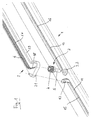
- a guide rail 1 which is fixed to a fixed component, namely a fixed window, a motor vehicle.
- the guide rail 1 is manufactured as an extruded profile with inserts. It has a first guide groove 11 and a second guide groove 12, each extending in the longitudinal direction of the guide rail 1 and which are aligned with each other. The right end of the first guide groove 11 and the left end of the second guide groove 12 are spaced from each other. In the region of this distance, a recess 23 is provided in the guide rail 1 between the guide grooves 11, 12, in which a gear 3 is rotatably mounted.
- the gear 3 comprises a circumferential ring gear 4, which protrudes in the mounted position from the recess 23 upwards, and a bolt 5 which is rotatably mounted in the recess 23.
- the bolt 5 is further driven by an electric motor (not shown in the drawing).
- the electric motor may be attached to the guide rail 1 or another part of the fixed component or another part of the vehicle.
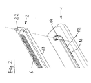
- a rack is fixed, which is designed as a tooth cam 2 and which has a toothing 6 and two guide pins 21, 22.
- the tooth curve 2 can be integrated into the encapsulation of the movable component.
- the first guide pin 21 engages in the first guide groove 11, the second guide pin 22 engages in the second guide groove 12 a. Further engages in the mounted state of the ring gear 4 of the gear 3 in the toothing 6 of the tooth curve 2 a.
- the bolts 21, 22 are removable.
- the teeth of the toothing 6 of the tooth curve 2 point in the horizontal direction.
- the axis of rotation of the ring gear 4 of the gear 3 extends in the vertical direction.
- the guide grooves 11, 12 each have a first section 15, 16 and a second section 13, 14.
- the first sections 15, 16 are rectilinear. They run in the longitudinal direction of the guide rail 1.
- the second sections 13, 14 extend at an angle of about 45 ° to the first portions 15, 16.
- the first sections 15, 16, the tooth curve 2 and with it the movable member is moved along the fixed component. This movement takes place in a plane which is substantially parallel with that of the stationary component and which lies on the inside of the fixed component.
- the second sections 13, 14 serve to guide the toothed curve 2 and with it the movable component out of this plane into the closed position, in which the outer surface of the movable component is substantially flush with the outer surface of the stationary component.
- the toothing 6 of the toothed curve 2 has a section 17 which extends in the longitudinal direction of the guide rail 1, and a section 18 which extends at an angle of approximately 45 ° thereto.
- the toothing 6 is a straight toothing. It can also be designed as helical toothing, which entails a higher manufacturing outlay, which, however, increases the smoothness, reduces the noise formation during operation and reduces the mechanical load and thus the service life can be increased.
- the tooth curve 2 is closed by a circumferential web 19.
- the circumferential web 19 extends parallel to the toothing 6 of the toothed curve 2 and at a distance thereto, wherein the distance substantially corresponds to the diameter of the toothed rim 4 of the toothed wheel 3.
- the portion 17 of the toothing 6 is used for the movement of the movable member along the fixed component.
- the portion 18 of the toothing 6 serves for the movement of the movable member in the closed position.
- the electric motor which is designed as a geared motor, can drive the gear 3 directly. However, he can also drive the gear 3 indirectly, for example via a flexible shaft, a fixed or flexible threaded element or a rack or a toothed belt.
- the sequence of movement of the movable member is determined by the guide grooves 11, 12 in the guide rail 1, in which the guide pins 21, 22 slide.
- the movable member is driven in the manner described, many components can be omitted, which are required in a manual operation of the movable member. Furthermore, the further advantage can be achieved that less space is needed in the field of view and no covers for the handle mechanism are required, which benefits the perceived value of the sliding window. Another advantage is that higher clamping forces can be achieved than with comfortable manual operation. As a result, the tightness of the sliding window can be increased, in particular in "flush sliding windows", in which the movable component is aligned in the closed position with the stationary component. Another achievable advantage is the increase in comfort by simple key operation of the window, possibly from different position from the vehicle and also by a possible remote control, in particular a radio remote control or infrared remote control.
- Fig. 5 shows the tooth curve 2 shown in Figs. 1, 2 and 3 with various reinforcements 24, 25, 26, 27, 28.
- the toothing 6 is in section 18, which serves for the movement of the movable member in the closed position, particularly loaded. Accordingly, this section 18 is to be strengthened.
- various reinforcements are shown for the sake of simplified graphic representation, which are partly also in a not particularly stressed area. This representation serves to demonstrate the various forms of reinforcements, regardless of the position within the toothing 6. Furthermore, in practice only one of the toothings shown in FIG. 5 is used in most cases.
- the reinforcement 24 is a plastic or metal insert having at least two or more teeth and an area connecting the teeth includes.
- the surfaces of the teeth of the reinforcement 24 form part of the surface of the toothing 6 of the tooth curve 2. Accordingly, the material of the reinforcement 24 and friction and sliding partner of the driving sprocket 4.
- the material of the reinforcement 24 can be adapted to the higher load.
- the modified reinforcements 25 correspond in the material of the reinforcement 24.
- individual teeth are used in the reinforcements. It can, as in the case shown, two teeth 25 are used. However, it is also possible to provide only one or more than two teeth 25.
- the reinforcement 26 is a completely overmolded insert.
- the material of the tooth curve 2 is plastic.
- the insert 26 may be made of a suitable plastic or metal.
- the reinforcement 26 does not form part of the surface of the toothing 6 of the tooth curve 2.
- the combination of materials toothed ring 4 - toothing 6 is therefore the same in the region of the reinforcement 26 as in the remaining area. Accordingly, in the region of the reinforcement 26, there are no material transitions of different materials, in particular not a material transition from a hard to a soft material. As a result, there is no noise change in this area.
- the Zahnfußfestmaschine is increased, but less strong than the reinforcements 24 and 25.
- Another advantage of the reinforcement 26 is that the associated depositor can be easily configured.
- the insert which forms the reinforcement 26 can have greater tolerances. He also need not contain the tooth shape of the toothing 6. This offers a manufacturing and cost advantage.
- the reinforcements 27 correspond to those of the reinforcement 26. In contrast to the reinforcement 26, however, individual teeth are used in the reinforcement 27. It can, as shown in the drawing, two teeth 27 may be provided. However, it is also possible to provide one tooth or more than two teeth 27.
- the reinforcement 28 is formed by a sheet metal section which is inserted into a tooth of the toothing 6. However, it is also possible to use a sheet metal section 28 in more than one tooth. The use of a sheet metal section 28 offers further cost advantages through the simple manufacture of the component. In the production of the reinforcement 28, however, must be used with a Zustoryautomaten.
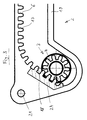
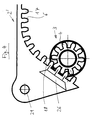
- a reinforcement 24 is used in section 18, which corresponds substantially to the reinforcement 24 in Fig. 5.
- a reinforcement 26 is used in section 18 of the toothing 6, which corresponds substantially to the reinforcement 26 in Fig. 5.
- the invention By the invention, the forces occurring over a large area in the component, ie in the gear and / or the rack, transmitted to keep the allowable surface pressure (voltage) at a low level.
- the invention can be used for power transmissions of all kinds, in particular for drives for sliding windows, Sliding doors, in particular electric sliding doors, and window regulators, in particular rack-lift windows.
- the service life can be increased. Furthermore, the better material properties of the reinforcement can be used in partial areas of the drive. In particular, the higher permissible voltage of the amplification can be used here. Further, it is possible to increase the temperature resistance. It is possible to increase the service life over time and temperature.
- noise minimization can be achieved by using friction-optimized materials in the low-load range.
- a far greater low load range is present, for example 95% of the total travel.
- standard materials, especially standard plastics, in the lightly loaded area can reduce costs.
- the highly loaded area which requires reinforcement and with it high-quality materials, accounts for only a small proportion of the component volume of, for example, 3% to 5%.
- a further advantage is that the technical injection molding process can be used, which brings cost advantages over other methods, especially against milling process.
- the manufacturing process can be improved because only a relatively small deposit must be made of a more expensive material.
- weight advantages can be achieved.
- a plastic having a density of, for example, 1.5 g / cm 3 can be used. Only in the heavily loaded area is a heavier material, such as a metal with a density of, for example, 7.8 g / cm 3 .
- a reinforcement is used which can be formed by a higher-strength component and which can functionally process the described loads in the long run.
- the Zahnfußschreib can be in the order of 20 N / mm 2 .
- the reinforcement may be in the form of an insert, an injection or an otherwise clearance-free fixed part, which is connected to the remaining, larger part of non-heavy-duty material designed.
- the reinforcement can also be integrated into the less resilient material by mixing a firmer material, optionally with a gradual change in the material properties, during production, preferably steplessly.
- a firmer material for the production of a large form of inexpensive plastic can be used, are introduced into the small parts of steel or PEEK.
- cheap manufacturing processes are possible.
- the surface of the gear and / or the rack may be inaccurate and / or rough in the lightly loaded portion.
- an improved surface may be used, such as a polished surface or a surface that is otherwise advantageously structured.
- the lightly loaded section of a particularly soft rolling, quiet material can be made.
Landscapes
- Engineering & Computer Science (AREA)
- General Engineering & Computer Science (AREA)
- Mechanical Engineering (AREA)
- Power-Operated Mechanisms For Wings (AREA)
Applications Claiming Priority (2)
| Application Number | Priority Date | Filing Date | Title |
|---|---|---|---|
| DE102006011026 | 2006-03-09 | ||
| DE102006026754A DE102006026754B4 (de) | 2006-03-09 | 2006-06-08 | Schiebefenster, Schiebetüre oder bewegliches Fenster für ein Fahrzeug, insbesondere ein Kraftfahrzeug |
Publications (1)
| Publication Number | Publication Date |
|---|---|
| EP1832704A2 true EP1832704A2 (fr) | 2007-09-12 |
Family
ID=38133231
Family Applications (1)
| Application Number | Title | Priority Date | Filing Date |
|---|---|---|---|
| EP20070004262 Withdrawn EP1832704A2 (fr) | 2006-03-09 | 2007-03-01 | Engrenage pour une fenêtre coulissante de véhicule automobile |
Country Status (2)
| Country | Link |
|---|---|
| EP (1) | EP1832704A2 (fr) |
| DE (1) | DE102006026754B4 (fr) |
Cited By (9)
| Publication number | Priority date | Publication date | Assignee | Title |
|---|---|---|---|---|
| EP1837218A3 (fr) * | 2006-03-22 | 2009-07-29 | DURA Automotive Body & Glass Systems GmbH | Fenêtre coulissante pour un véhicule automobile |
| CN103670110A (zh) * | 2013-11-25 | 2014-03-26 | 无锡睿网科技有限公司 | 一种移动窗结构 |
| CN104563720A (zh) * | 2014-10-28 | 2015-04-29 | 浙江吉利控股集团有限公司 | 车窗玻璃升降装置 |
| CN105667273A (zh) * | 2016-03-25 | 2016-06-15 | 官木喜 | 一种电动四轮车 |
| CN105840782A (zh) * | 2016-04-27 | 2016-08-10 | 太仓宝达齿条有限公司 | 一种耐磨耐腐尼龙齿条 |
| CN111717006A (zh) * | 2020-07-28 | 2020-09-29 | 南京康尼机电股份有限公司 | 一种电动微塞滑移顶盖门系统 |
| WO2020216511A1 (fr) * | 2019-04-26 | 2020-10-29 | Zf Friedrichshafen Ag | Procédé de fabrication d'un module de crémaillère ainsi que module de crémaillère et servofrein |
| CN111868415A (zh) * | 2018-03-16 | 2020-10-30 | 诺托弗朗克门窗技术有限责任公司 | 齿轮、用于齿形元件传动机构的齿形元件以及相应的齿形元件传动机构 |
| CN112343992A (zh) * | 2019-08-09 | 2021-02-09 | 米巴烧结奥地利有限公司 | 齿轮 |
Family Cites Families (4)
| Publication number | Priority date | Publication date | Assignee | Title |
|---|---|---|---|---|
| DE837248C (de) * | 1951-01-19 | 1952-04-21 | Maschf Augsburg Nuernberg Ag | Vorrichtung zur Betaetigung von Schiebefenstern fuer Schienen- und Strassenfahrzeuge |
| DE3123554C2 (de) * | 1981-06-13 | 1984-03-22 | Webasto-Werk W. Baier GmbH & Co, 8035 Gauting | Flexible Kunststoff-Zahnstange |
| DE3346504A1 (de) * | 1983-12-22 | 1985-07-04 | Dansk Gartneri-Teknik A/S, Broendby Strand | Zahnstangenmechanismus, insbesondere fuer eine oeffnungs- und schliesseinrichtung fuer dachfenster und -luken |
| EP1092572B1 (fr) * | 1999-10-14 | 2005-12-07 | Calsonic Kansei Corporation | Bloc porte coulissante d'une installation de conditionnement d'air d'automobile |
-
2006
- 2006-06-08 DE DE102006026754A patent/DE102006026754B4/de not_active Expired - Fee Related
-
2007
- 2007-03-01 EP EP20070004262 patent/EP1832704A2/fr not_active Withdrawn
Cited By (11)
| Publication number | Priority date | Publication date | Assignee | Title |
|---|---|---|---|---|
| EP1837218A3 (fr) * | 2006-03-22 | 2009-07-29 | DURA Automotive Body & Glass Systems GmbH | Fenêtre coulissante pour un véhicule automobile |
| EP2251222A3 (fr) * | 2006-03-22 | 2011-01-05 | DURA Automotive Body and Glass Systems GmbH | Fenêtre coulissante pour un véhicule automobile |
| CN103670110A (zh) * | 2013-11-25 | 2014-03-26 | 无锡睿网科技有限公司 | 一种移动窗结构 |
| CN104563720A (zh) * | 2014-10-28 | 2015-04-29 | 浙江吉利控股集团有限公司 | 车窗玻璃升降装置 |
| CN104563720B (zh) * | 2014-10-28 | 2017-02-08 | 浙江吉利控股集团有限公司 | 车窗玻璃升降装置 |
| CN105667273A (zh) * | 2016-03-25 | 2016-06-15 | 官木喜 | 一种电动四轮车 |
| CN105840782A (zh) * | 2016-04-27 | 2016-08-10 | 太仓宝达齿条有限公司 | 一种耐磨耐腐尼龙齿条 |
| CN111868415A (zh) * | 2018-03-16 | 2020-10-30 | 诺托弗朗克门窗技术有限责任公司 | 齿轮、用于齿形元件传动机构的齿形元件以及相应的齿形元件传动机构 |
| WO2020216511A1 (fr) * | 2019-04-26 | 2020-10-29 | Zf Friedrichshafen Ag | Procédé de fabrication d'un module de crémaillère ainsi que module de crémaillère et servofrein |
| CN112343992A (zh) * | 2019-08-09 | 2021-02-09 | 米巴烧结奥地利有限公司 | 齿轮 |
| CN111717006A (zh) * | 2020-07-28 | 2020-09-29 | 南京康尼机电股份有限公司 | 一种电动微塞滑移顶盖门系统 |
Also Published As
| Publication number | Publication date |
|---|---|
| DE102006026754A1 (de) | 2007-09-13 |
| DE102006026754B4 (de) | 2009-02-05 |
Similar Documents
| Publication | Publication Date | Title |
|---|---|---|
| EP1643064B1 (fr) | Fenêtre coulissante, notamment pour un véhicule automobile | |
| DE102013003830B4 (de) | Spindelantrieb für ein Verstellelement eines Kraftfahrzeugs | |
| DE102019211932A1 (de) | Türantriebsvorrichtung mit einer eine Führungsschiene umfassenden Getriebebaugruppe | |
| DE102019126568B4 (de) | Verstellmechanismus für einen Fahrzeugsitz und Fahrzeugsitz mit einem solchen Verstellmechanismus | |
| EP1337732B1 (fr) | Leve-vitre a bras pour un vehicule automobile | |
| WO2019030039A1 (fr) | Entraînement de broche pour élément de fermeture d'un véhicule atomobile | |
| EP3274612B1 (fr) | Unité d'actionnement pour un entraînement de fermeture d'une serrure de véhicule à moteur | |
| WO1992022439A1 (fr) | Entrainement de broche pour un dispositif de reglage de sieges de vehicules | |
| DE102006026754B4 (de) | Schiebefenster, Schiebetüre oder bewegliches Fenster für ein Fahrzeug, insbesondere ein Kraftfahrzeug | |
| DE102009011120A1 (de) | Einstelleinrichtung für die Fensterscheibe eines Fensterhebers | |
| EP4158138B1 (fr) | Unité d'entraînement destinée à des applications de véhicule automobile | |
| EP3800315B1 (fr) | Module d'entrainement pour le deplacement d'un element de fermeture par rapport a un cadre dans une ouverture de batiment | |
| WO2015154920A1 (fr) | Dispositif de direction électromécanique comportant une roue dentée et procédé de fabrication d'une roue dentée | |
| EP3486530B1 (fr) | Porte-satellites | |
| DE102018213360A1 (de) | Mitnehmer für einen Fahrzeugfensterheber und Fahrzeugfensterheber | |
| EP1545269B1 (fr) | Mecanisme de commande a moteur electrique pour meubles | |
| EP1046000B1 (fr) | Dispositif pour deplacer une piece, notamment dans un vehicule a moteur, comportant un mecanisme de reglage | |
| DE102009003280B4 (de) | Gewindespindel-Verstellantrieb | |
| EP1002923A2 (fr) | Dispositif d'ouverture et de fermeture d'une ouverture dans une paroi au moyen d'une porte coulissante | |
| DE19849245C1 (de) | Antriebsvorrichtung für ein bewegbares Teil, insbesondere ein Seitenausstellfenster eines Fahrzeuges | |
| DE2912666A1 (de) | Verbindungseinrichtung fuer ein antriebskabel | |
| EP3405698A1 (fr) | Actionneur équipé d'une vis creuse | |
| DE102009038232A1 (de) | Servolenkung | |
| DE102023113634A1 (de) | Fahrzeugtürbaugruppe mit einer Antriebsvorrichtung | |
| DE102005062999A1 (de) | Elektromotorischer Möbelantrieb |
Legal Events
| Date | Code | Title | Description |
|---|---|---|---|
| PUAI | Public reference made under article 153(3) epc to a published international application that has entered the european phase |
Free format text: ORIGINAL CODE: 0009012 |
|
| AK | Designated contracting states |
Kind code of ref document: A2 Designated state(s): AT BE BG CH CY CZ DE DK EE ES FI FR GB GR HU IE IS IT LI LT LU LV MC MT NL PL PT RO SE SI SK TR |
|
| AX | Request for extension of the european patent |
Extension state: AL BA HR MK YU |
|
| STAA | Information on the status of an ep patent application or granted ep patent |
Free format text: STATUS: THE APPLICATION IS DEEMED TO BE WITHDRAWN |
|
| 18D | Application deemed to be withdrawn |
Effective date: 20131001 |