EP1832708A2 - Träger zum Tragen einer Rollladenwelle und Montage des Rollladens mit einem solchen Träger - Google Patents
Träger zum Tragen einer Rollladenwelle und Montage des Rollladens mit einem solchen Träger Download PDFInfo
- Publication number
- EP1832708A2 EP1832708A2 EP07290284A EP07290284A EP1832708A2 EP 1832708 A2 EP1832708 A2 EP 1832708A2 EP 07290284 A EP07290284 A EP 07290284A EP 07290284 A EP07290284 A EP 07290284A EP 1832708 A2 EP1832708 A2 EP 1832708A2
- Authority
- EP
- European Patent Office
- Prior art keywords
- breakable
- console
- console according
- shaft
- peripheral
- Prior art date
- Legal status (The legal status is an assumption and is not a legal conclusion. Google has not performed a legal analysis and makes no representation as to the accuracy of the status listed.)
- Granted
Links
Images

Classifications
-
- E—FIXED CONSTRUCTIONS
- E06—DOORS, WINDOWS, SHUTTERS, OR ROLLER BLINDS IN GENERAL; LADDERS
- E06B—FIXED OR MOVABLE CLOSURES FOR OPENINGS IN BUILDINGS, VEHICLES, FENCES OR LIKE ENCLOSURES IN GENERAL, e.g. DOORS, WINDOWS, BLINDS, GATES
- E06B9/00—Screening or protective devices for wall or similar openings, with or without operating or securing mechanisms; Closures of similar construction
- E06B9/02—Shutters, movable grilles, or other safety closing devices, e.g. against burglary
- E06B9/08—Roll-type closures
- E06B9/11—Roller shutters
- E06B9/17—Parts or details of roller shutters, e.g. suspension devices, shutter boxes, wicket doors, ventilation openings
- E06B9/174—Bearings specially adapted therefor
Definitions
- the invention relates to a console for supporting a shutter tree in a reservation above an opening, such as a window or door, of a building, the shutter being arranged between two consoles, each provided respectively towards one end of the reservation, and the shaft protruding beyond at least one of the consoles to cooperate with a rotating drive device located on the side of the console opposite the flap.
- the target console is of the kind that consist of a single piece and have a breakable central portion adjoining a peripheral portion by fasteners to break, the detachment of the central portion by breaking the fasteners to access the device drive for a maintenance or replacement operation.
- a console of this kind is known from FR-A-2,773,841 in the name of the same plaintiff company.
- the console that supports the winding shaft of the shutter is generally not easily removable when the installation is complete, with or without a safe.
- the central part breakable according FR-A-2,773,841 allows, after detachment, access to the drive device after installation of the shutter, in particular for a maintenance operation.
- the object of the invention is, above all, to provide a console of the kind defined previously which makes it possible, in the event of intervention requiring the detachment of the central part, to avoid in most cases having to use an additional piece to reassemble the shutter shaft and the drive.
- the invention also aims to allow this console to achieve economically.
- a console of the kind defined above is characterized in that the breakable portion comprises auxiliary fastening means while the peripheral portion comprises conjugate fastening means of these auxiliary means, these auxiliary and conjugate fastening means being arranged so as to cooperate after detachment of the breakable portion and rotation parallel to, or in the plane of the peripheral portion, for attachment of the breakable portion in another position.
- the auxiliary fastening means and the conjugate fastening means may be constituted by holes facing each other, the assembly of the parts being provided by screws, rivets, or equivalent elements.
- the breakable portion has an elongated contour, with a large horizontal dimension when the bracket is in place and the breakable portion is not detached, and the auxiliary fastening means are located towards the end zones of the large dimension, areas which, after rotation of the breakable portion, are opposite corresponding parts of the contour of the peripheral portion, provided with the conjugate fixing means.
- the breakable portion advantageously comprises an oblong hole, with its large horizontal dimension and orthogonal to the drive shaft when the console is installed.
- Above and below the slot may be provided several holes spaced in the longitudinal direction for the attachment of a bearing, adjustable in the direction of the depth.
- the length of the central breakable portion is greater than the width of an opening of the peripheral portion housing the breakable portion such that, after cutting the central portion and rotation, the ends of the central portion cover portions of the portion peripheral.
- At least one hole is provided near each longitudinal end of the central portion to form the auxiliary fastening means.
- In the peripheral contour above and below the breakable portion are provided horizontally aligned holes to cooperate with the holes in the rotated central portion after detachment.
- the breakable portion has a substantially circular outline.
- the outline of the breakable part can be that of a polygon preferably writable in a circle. This polygon could have a number of sides between three, which corresponds to a triangle, and an infinite number, which corresponds to a circle.
- the auxiliary fastening means of the breakable portion can then be provided on at least two radially projecting tabs.
- the peripheral portion may comprise at least two notches open towards the breakable part, in which are housed the tabs of the breakable part before detachment.
- the central breakable portion may be in the form of a circular contour disc.
- the tabs are preferably diametrically opposed, projecting radially.
- the legs are arched so that the face of each lug located on the side of the disk is set back from this disk by a distance equal to the thickness of the strip or the sheet constituting the console.
- the height of an indentation of the peripheral portion is advantageously chosen less than the width of an apron blade of the roller shutter so that there is no risk of attachment of the blades.
- the invention also relates to a shutter assembly in a reservation, with or without a box, above an opening, such as a window or door of a building, two consoles being provided in the reservation, respectively one towards each end of the reservation, to support the winding shaft of the shutter, this shaft projecting beyond at least one of the consoles to cooperate with a rotary drive device located on the opposite side of the console shutter, characterized in that at least the console located in the vicinity of the rotary drive device is as defined above.
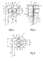
- Figs. 1 and 2 can be seen a console C made from a strip or sheet metal, to support a tree 1 (Fig.2) of shutter B in a reservation 2 of the masonry above an opening A, such as a window or door of a building. If necessary, a chest could be installed in reservation 2 and surround the shutter and its shaft.
- the console C has a central hole 3 provided for the passage of the shaft 1 supported by a bearing 3a fixed to the console.
- the hole 3 is oblong, with its large horizontal dimension orthogonal to the shaft 1.
- Above and below the hole 3 are provided a plurality of holes 4 spaced in the longitudinal direction of the hole 3.
- the holes 4 are used for fixing the bearing 3a for the shaft 1, and the series of holes 4 allows adjustment of the position of the bearing following the depth of the reservation 2.
- the console C comprises rearwards, at its lower part, a vertical leg 5 for attachment to a frame of carpentry, not shown.
- the console C is in one piece (alternatively, the tab could be attached to the console) and has a central part C1 breakable adjacent to a peripheral portion C2 by fasteners 6 to break.
- the breakable portion C1 is constituted by an elongated central portion 7, substantially rectangular, with large straight horizontal sides connected by convex curvilinear sides.
- the peripheral portion C2 has an opening 8 whose contour is parallel to that of the central portion 7.
- the length L of the central portion 7 is greater than the width W of the opening 8.
- At least one hole 9, 10 is provided near each longitudinal end of the central portion 7, and constitutes an auxiliary fixing means of this part.
- the console C can be manufactured economically by cutting a sheet or strip.
- a device T may consist of a winch to be operated with a rod, or a pulley to be operated with a strap, or an electric drive device.
- the console C can no longer be disassembled so that the drive device T is no longer accessible from the space where the flap B is located which remains accessible thanks to a hatch not shown .
- the operator When an intervention must take place at the drive device T, in particular an operation to be performed by an after-sales service (SAV) for the maintenance or replacement of the device T, the operator, after having deposited the flap B, can cut with a clamp the fasteners 6 to detach the central breakable portion 7 of the peripheral contour C2.
- SAV after-sales service
- the operator can reuse the central portion 7 as a support of the shaft 1. For this, after having cleared the part 7 of the opening 8, the operator rotates the part 7 90 ° parallel to its plane, and places the hole 9 opposite a suitable hole 11, as shown in Fig.3, for the depth adjustment of the shaft 1. The operator then assembles the piece 7 and the peripheral contour C2 using a screw, or equivalent means, engaged and locked in the holes 9 and 11. A similar operation is performed at the hole 10 and a hole 12 of the contour C2.
- the central portion 7 detached and fixed against the peripheral contour C2 is located on the side of the flap B and is a slight extra thickness. For this reason, it avoids the console play a guiding flap flange role that might hang the extra thickness.
- FIGS. 4 to 6 show an alternative embodiment according to which, after detachment of the central portion C1, rotation and attachment to the peripheral portion C2, it is possible to keep the central portion C1 in the same plane as the portion C2.
- the central breakable portion C1 is formed by a disk 13 with a circular contour.
- the auxiliary fixing means of the breakable portion C1 are provided, in the form of holes 9, 10, on at least two lugs 14, preferably diametrically opposed, projecting radially. We find also the holes 11 and 12 (conjugated fastening means) in the peripheral contour C2.
- the disc 13 is secured to the peripheral contour C2, for example by four fasteners 6 spaced 90 ° and arranged along the bisectors of the angles formed by the horizontal and vertical direction.
- the outline C2 has an opening 8 'in which is located the disk 13 surrounded by a light 8'a interrupted by the fasteners 6.
- the peripheral portion C2 comprises at least two notches 15, generally rectangular or square, open towards the breakable portion C1 and in which are housed the tabs 14 before detachment of the breakable portion C1.
- the height h of a notch 15 is chosen to be less than the width of a blade E (FIG. 2) of the rolling shutter apron so that there is no risk of the blades being hooked.
- FIG. 4 shows holes 16 in the breakable disc 13 for fixing the drive device T.
- the breakable disc 13 comprises in its central part a housing G for a bearing of the shaft 1.
- the tabs 14 could be in the plane of the disc 13 but, in this case, after detaching the disc, rotating 90 ° and fixing the tabs 14 against the peripheral portion C2, the disc 13 would be in excess of the peripheral portion C2, in the same way as in Fig.3.
- cambered tabs are provided so that the face of each lug 14 located on the side of the disk 13 is parallel to the disk but recessed by a distance equal to the thickness of the strip or the sheet constituting the console C and therefore the parts C2 and C1.
- the console C can thus serve as guiding flange to the roller shutter without risk of attachment of the blades by an extra thickness both in the disk configuration 13 attached to the peripheral portion C2 (Fig.4) that in the disk configuration 13 detached and fixed again on the peripheral portion C2 with screws S as illustrated in FIG. 5 and 6.
- the console C according to FIG. 4 to 6 has substantially the shape of a rectangular or square plate whose angles of the front part are sliced at 45 °.
- the implementation of the console of Fig.4 to 6 is similar to that previously discussed.
- the console is fixed in the reservation for example by means of tabs 17 curved at right angles provided on its periphery.
- console C When the installation of the shutter in the reservation 2 is complete, the console C is no longer easily removable, and is in the configuration of Fig.4 with the central disk 13 adjacent to the C2 part.
- the central disk 13 is rotated 90 ° in its plane which remains that of the peripheral portion C2, and the cambered legs 14 are applied against the face of the peripheral portion C2 opposite the roller shutter with facing holes 9, 10 and holes 11, 12 and insertion of a fixing screw S.
- the invention has the advantage of not requiring, in general, an additional room in case of intervention on a shutter in place. It is enough to recover the central piece C1 and to rotate it 90 ° in its plane, or parallel to its plane, then to fix it in the part C2.
- the rotation of the breakable part after detachment for fixing in another position is 90 °.
- the outline of the breakable part can be that of a polygon, preferably writable in a circle.
- This polygon could have a number of sides between three, which corresponds to a triangle, and an infinite number, which corresponds to a circle.
- the solution proposed by the invention also has the advantage of achieving a saving of material since the breakable portion can be used, after detachment, to support the shaft and the drive device again. An extra room is not usually necessary.
Landscapes
- Engineering & Computer Science (AREA)
- Structural Engineering (AREA)
- Architecture (AREA)
- Civil Engineering (AREA)
- Operating, Guiding And Securing Of Roll- Type Closing Members (AREA)
- Spinning Or Twisting Of Yarns (AREA)
- Rollers For Roller Conveyors For Transfer (AREA)
- Wing Frames And Configurations (AREA)
- Vehicle Step Arrangements And Article Storage (AREA)
Applications Claiming Priority (1)
| Application Number | Priority Date | Filing Date | Title |
|---|---|---|---|
| FR0602060A FR2898380B1 (fr) | 2006-03-08 | 2006-03-08 | Console pour supporter un arbre de volet roulant, et montage de volet roulant avec une telle console. |
Publications (3)
| Publication Number | Publication Date |
|---|---|
| EP1832708A2 true EP1832708A2 (de) | 2007-09-12 |
| EP1832708A3 EP1832708A3 (de) | 2007-12-05 |
| EP1832708B1 EP1832708B1 (de) | 2010-09-29 |
Family
ID=37563210
Family Applications (1)
| Application Number | Title | Priority Date | Filing Date |
|---|---|---|---|
| EP07290284A Active EP1832708B1 (de) | 2006-03-08 | 2007-03-06 | Träger zum Tragen einer Rollladenwelle und Montage des Rollladens mit einem solchen Träger |
Country Status (5)
| Country | Link |
|---|---|
| EP (1) | EP1832708B1 (de) |
| AT (1) | ATE483089T1 (de) |
| DE (1) | DE602007009439D1 (de) |
| ES (1) | ES2352515T3 (de) |
| FR (1) | FR2898380B1 (de) |
Family Cites Families (3)
| Publication number | Priority date | Publication date | Assignee | Title |
|---|---|---|---|---|
| FR2773841B1 (fr) * | 1998-01-19 | 2000-03-31 | Zurfluh Feller | Console pour mecanisme de volet roulant comportant une partie centrale secable |
| FR2801632B1 (fr) * | 1999-11-30 | 2002-01-18 | Simbac S P A | Dispositif de fixation d'un organe d'entrainement et mecanisme de manoeuvre d'une installation de fermeture ou de protection solaire comprenant un tel dispositif |
| FR2873742B1 (fr) * | 2004-08-02 | 2006-09-22 | Deprat Jean Sa Sa | Dispositif de fermeture et d'ouverture d'un ouvrant, muni d'une joue presentant un flasque amovible |
-
2006
- 2006-03-08 FR FR0602060A patent/FR2898380B1/fr not_active Expired - Fee Related
-
2007
- 2007-03-06 AT AT07290284T patent/ATE483089T1/de not_active IP Right Cessation
- 2007-03-06 EP EP07290284A patent/EP1832708B1/de active Active
- 2007-03-06 ES ES07290284T patent/ES2352515T3/es active Active
- 2007-03-06 DE DE602007009439T patent/DE602007009439D1/de active Active
Also Published As
| Publication number | Publication date |
|---|---|
| ATE483089T1 (de) | 2010-10-15 |
| FR2898380B1 (fr) | 2009-07-03 |
| EP1832708A3 (de) | 2007-12-05 |
| DE602007009439D1 (de) | 2010-11-11 |
| ES2352515T3 (es) | 2011-02-21 |
| EP1832708B1 (de) | 2010-09-29 |
| FR2898380A1 (fr) | 2007-09-14 |
Similar Documents
| Publication | Publication Date | Title |
|---|---|---|
| EP1127394B1 (de) | Leitungshalterung auf einem trägerelement mit mindestens einer öffnung und tragender aufbau für kabelführung. | |
| EP2055866B1 (de) | Pfahl für Einzäunung mit Maschendraht und solche Pfähle umfassende Einzäunung | |
| EP1192693A1 (de) | Befestigungsvorrichtung für kabelrinne aus metalldrahtgitter und damit ausgerüstete kabelrinne | |
| FR2520781A1 (fr) | Cloison formee de panneaux montes sur armatures et panneau susceptible d'etre utilise pour la realisation d'une telle cloison | |
| EP2841663A1 (de) | Vorrichtung zur abdeckung einer gebäudestruktur und mit einer solchen vorrichtung abgedeckte struktur | |
| EP1832708B1 (de) | Träger zum Tragen einer Rollladenwelle und Montage des Rollladens mit einem solchen Träger | |
| EP2075888B1 (de) | Mehrplatzhalterung für elektrische Geräte zur horizontalen und vertikalen Montage, eine mit einer solchen Mehrplatzhalterung mit Querträger umfassende Baugruppe und ein elektrisches Gerät mit so einer Baugruppe | |
| EP1741938B1 (de) | Käfiganordnung für eine Käfigmutter | |
| EP0770832B1 (de) | Modulares Gitter | |
| EP2314820B1 (de) | Halterungsvorrichtung eines Rollladens, und mit dieser Vorrichtung zu montierender Rollladen | |
| EP3580404B1 (de) | Verfahren zum montieren einer gestreckten flexiblen abdeckung auf einem montagerahmen und montagerahmen zur durchführung des verfahrens | |
| EP0762586B1 (de) | Gehäuse für elektrische Geräte | |
| FR2888271A1 (fr) | Panneaux, poteaux de cloture et cloture comprenant de tels panneaux et poteaux | |
| EP2355282B1 (de) | Gerätehalterung und mit einer solchen Gerätehalterung ausgestattetes elektrisches Gerät | |
| EP2575182B1 (de) | Befestigungsvorrichtung für mindestens ein Photovoltaikmodul auf einer tragenden Struktur, Solarplatte und Baugruppe, die mindestens zwei Solarplatten umfasst, die jeweils mit einer solchen Vorrichtung ausgestattet sind | |
| FR2896530A1 (fr) | Dispositif de support pour volet roulant et ensemble de volet roulant a monter avec un tel dispositif | |
| EP2299128B1 (de) | Verbindungselement einer Untereinheit, insbesondere eines flexiblen Paneels mit einem länglichen Element | |
| EP1617155B1 (de) | Lüftungsgitter | |
| FR2522044A1 (fr) | Profile pour la realisation de cloisons amovibles et systeme de cloison utilisant ce profile | |
| EP1409802A2 (de) | Eckpfosten zum verbinden von isolationspaneelen | |
| EP4455429A1 (de) | Sicht- oder verdunkelungspaneel für starre gitterzäune und befestigungsverfahren dafür | |
| WO1998053157A1 (fr) | Element de couverture | |
| EP4438832A1 (de) | Geländerkit und geländer | |
| EP3059376A1 (de) | Verfahren zum einbau einer verschluss- oder sonnenschutzanlage, halterungssystem und entsprechende anlage | |
| FR3037609A1 (fr) | Dispositif a coulissement pour la pose et la depose d'un volet roulant |
Legal Events
| Date | Code | Title | Description |
|---|---|---|---|
| PUAI | Public reference made under article 153(3) epc to a published international application that has entered the european phase |
Free format text: ORIGINAL CODE: 0009012 |
|
| 17P | Request for examination filed |
Effective date: 20070317 |
|
| AK | Designated contracting states |
Kind code of ref document: A2 Designated state(s): AT BE BG CH CY CZ DE DK EE ES FI FR GB GR HU IE IS IT LI LT LU LV MC MT NL PL PT RO SE SI SK TR |
|
| AX | Request for extension of the european patent |
Extension state: AL BA HR MK YU |
|
| PUAL | Search report despatched |
Free format text: ORIGINAL CODE: 0009013 |
|
| AK | Designated contracting states |
Kind code of ref document: A3 Designated state(s): AT BE BG CH CY CZ DE DK EE ES FI FR GB GR HU IE IS IT LI LT LU LV MC MT NL PL PT RO SE SI SK TR |
|
| AX | Request for extension of the european patent |
Extension state: AL BA HR MK YU |
|
| AKX | Designation fees paid |
Designated state(s): AT BE BG CH CY CZ DE DK EE ES FI FR GB GR HU IE IS IT LI LT LU LV MC MT NL PL PT RO SE SI SK TR |
|
| GRAP | Despatch of communication of intention to grant a patent |
Free format text: ORIGINAL CODE: EPIDOSNIGR1 |
|
| GRAS | Grant fee paid |
Free format text: ORIGINAL CODE: EPIDOSNIGR3 |
|
| GRAA | (expected) grant |
Free format text: ORIGINAL CODE: 0009210 |
|
| AK | Designated contracting states |
Kind code of ref document: B1 Designated state(s): AT BE BG CH CY CZ DE DK EE ES FI FR GB GR HU IE IS IT LI LT LU LV MC MT NL PL PT RO SE SI SK TR |
|
| REG | Reference to a national code |
Ref country code: GB Ref legal event code: FG4D Free format text: NOT ENGLISH |
|
| REG | Reference to a national code |
Ref country code: CH Ref legal event code: EP |
|
| REG | Reference to a national code |
Ref country code: IE Ref legal event code: FG4D Free format text: LANGUAGE OF EP DOCUMENT: FRENCH |
|
| REF | Corresponds to: |
Ref document number: 602007009439 Country of ref document: DE Date of ref document: 20101111 Kind code of ref document: P |
|
| PG25 | Lapsed in a contracting state [announced via postgrant information from national office to epo] |
Ref country code: FI Free format text: LAPSE BECAUSE OF FAILURE TO SUBMIT A TRANSLATION OF THE DESCRIPTION OR TO PAY THE FEE WITHIN THE PRESCRIBED TIME-LIMIT Effective date: 20100929 Ref country code: AT Free format text: LAPSE BECAUSE OF FAILURE TO SUBMIT A TRANSLATION OF THE DESCRIPTION OR TO PAY THE FEE WITHIN THE PRESCRIBED TIME-LIMIT Effective date: 20100929 Ref country code: LT Free format text: LAPSE BECAUSE OF FAILURE TO SUBMIT A TRANSLATION OF THE DESCRIPTION OR TO PAY THE FEE WITHIN THE PRESCRIBED TIME-LIMIT Effective date: 20100929 |
|
| REG | Reference to a national code |
Ref country code: NL Ref legal event code: VDEP Effective date: 20100929 |
|
| REG | Reference to a national code |
Ref country code: ES Ref legal event code: FG2A Effective date: 20110209 |
|
| LTIE | Lt: invalidation of european patent or patent extension |
Effective date: 20100929 |
|
| PG25 | Lapsed in a contracting state [announced via postgrant information from national office to epo] |
Ref country code: SI Free format text: LAPSE BECAUSE OF FAILURE TO SUBMIT A TRANSLATION OF THE DESCRIPTION OR TO PAY THE FEE WITHIN THE PRESCRIBED TIME-LIMIT Effective date: 20100929 |
|
| PG25 | Lapsed in a contracting state [announced via postgrant information from national office to epo] |
Ref country code: SE Free format text: LAPSE BECAUSE OF FAILURE TO SUBMIT A TRANSLATION OF THE DESCRIPTION OR TO PAY THE FEE WITHIN THE PRESCRIBED TIME-LIMIT Effective date: 20100929 Ref country code: GR Free format text: LAPSE BECAUSE OF FAILURE TO SUBMIT A TRANSLATION OF THE DESCRIPTION OR TO PAY THE FEE WITHIN THE PRESCRIBED TIME-LIMIT Effective date: 20101230 Ref country code: LV Free format text: LAPSE BECAUSE OF FAILURE TO SUBMIT A TRANSLATION OF THE DESCRIPTION OR TO PAY THE FEE WITHIN THE PRESCRIBED TIME-LIMIT Effective date: 20100929 |
|
| REG | Reference to a national code |
Ref country code: IE Ref legal event code: FD4D |
|
| PG25 | Lapsed in a contracting state [announced via postgrant information from national office to epo] |
Ref country code: EE Free format text: LAPSE BECAUSE OF FAILURE TO SUBMIT A TRANSLATION OF THE DESCRIPTION OR TO PAY THE FEE WITHIN THE PRESCRIBED TIME-LIMIT Effective date: 20100929 Ref country code: PT Free format text: LAPSE BECAUSE OF FAILURE TO SUBMIT A TRANSLATION OF THE DESCRIPTION OR TO PAY THE FEE WITHIN THE PRESCRIBED TIME-LIMIT Effective date: 20110131 Ref country code: SK Free format text: LAPSE BECAUSE OF FAILURE TO SUBMIT A TRANSLATION OF THE DESCRIPTION OR TO PAY THE FEE WITHIN THE PRESCRIBED TIME-LIMIT Effective date: 20100929 Ref country code: IS Free format text: LAPSE BECAUSE OF FAILURE TO SUBMIT A TRANSLATION OF THE DESCRIPTION OR TO PAY THE FEE WITHIN THE PRESCRIBED TIME-LIMIT Effective date: 20110129 Ref country code: NL Free format text: LAPSE BECAUSE OF FAILURE TO SUBMIT A TRANSLATION OF THE DESCRIPTION OR TO PAY THE FEE WITHIN THE PRESCRIBED TIME-LIMIT Effective date: 20100929 Ref country code: RO Free format text: LAPSE BECAUSE OF FAILURE TO SUBMIT A TRANSLATION OF THE DESCRIPTION OR TO PAY THE FEE WITHIN THE PRESCRIBED TIME-LIMIT Effective date: 20100929 Ref country code: CZ Free format text: LAPSE BECAUSE OF FAILURE TO SUBMIT A TRANSLATION OF THE DESCRIPTION OR TO PAY THE FEE WITHIN THE PRESCRIBED TIME-LIMIT Effective date: 20100929 |
|
| PG25 | Lapsed in a contracting state [announced via postgrant information from national office to epo] |
Ref country code: IE Free format text: LAPSE BECAUSE OF FAILURE TO SUBMIT A TRANSLATION OF THE DESCRIPTION OR TO PAY THE FEE WITHIN THE PRESCRIBED TIME-LIMIT Effective date: 20100929 |
|
| PLBE | No opposition filed within time limit |
Free format text: ORIGINAL CODE: 0009261 |
|
| STAA | Information on the status of an ep patent application or granted ep patent |
Free format text: STATUS: NO OPPOSITION FILED WITHIN TIME LIMIT |
|
| PG25 | Lapsed in a contracting state [announced via postgrant information from national office to epo] |
Ref country code: DK Free format text: LAPSE BECAUSE OF FAILURE TO SUBMIT A TRANSLATION OF THE DESCRIPTION OR TO PAY THE FEE WITHIN THE PRESCRIBED TIME-LIMIT Effective date: 20100929 Ref country code: PL Free format text: LAPSE BECAUSE OF FAILURE TO SUBMIT A TRANSLATION OF THE DESCRIPTION OR TO PAY THE FEE WITHIN THE PRESCRIBED TIME-LIMIT Effective date: 20100929 |
|
| REG | Reference to a national code |
Ref country code: DE Ref legal event code: R097 Ref document number: 602007009439 Country of ref document: DE Effective date: 20110630 |
|
| PG25 | Lapsed in a contracting state [announced via postgrant information from national office to epo] |
Ref country code: MC Free format text: LAPSE BECAUSE OF NON-PAYMENT OF DUE FEES Effective date: 20110331 |
|
| REG | Reference to a national code |
Ref country code: CH Ref legal event code: PL |
|
| GBPC | Gb: european patent ceased through non-payment of renewal fee |
Effective date: 20110306 |
|
| PG25 | Lapsed in a contracting state [announced via postgrant information from national office to epo] |
Ref country code: MT Free format text: LAPSE BECAUSE OF FAILURE TO SUBMIT A TRANSLATION OF THE DESCRIPTION OR TO PAY THE FEE WITHIN THE PRESCRIBED TIME-LIMIT Effective date: 20100929 |
|
| PG25 | Lapsed in a contracting state [announced via postgrant information from national office to epo] |
Ref country code: LI Free format text: LAPSE BECAUSE OF NON-PAYMENT OF DUE FEES Effective date: 20110331 Ref country code: CH Free format text: LAPSE BECAUSE OF NON-PAYMENT OF DUE FEES Effective date: 20110331 |
|
| PG25 | Lapsed in a contracting state [announced via postgrant information from national office to epo] |
Ref country code: GB Free format text: LAPSE BECAUSE OF NON-PAYMENT OF DUE FEES Effective date: 20110306 |
|
| PG25 | Lapsed in a contracting state [announced via postgrant information from national office to epo] |
Ref country code: LU Free format text: LAPSE BECAUSE OF NON-PAYMENT OF DUE FEES Effective date: 20110306 Ref country code: CY Free format text: LAPSE BECAUSE OF FAILURE TO SUBMIT A TRANSLATION OF THE DESCRIPTION OR TO PAY THE FEE WITHIN THE PRESCRIBED TIME-LIMIT Effective date: 20100929 |
|
| PG25 | Lapsed in a contracting state [announced via postgrant information from national office to epo] |
Ref country code: BG Free format text: LAPSE BECAUSE OF FAILURE TO SUBMIT A TRANSLATION OF THE DESCRIPTION OR TO PAY THE FEE WITHIN THE PRESCRIBED TIME-LIMIT Effective date: 20101229 Ref country code: TR Free format text: LAPSE BECAUSE OF FAILURE TO SUBMIT A TRANSLATION OF THE DESCRIPTION OR TO PAY THE FEE WITHIN THE PRESCRIBED TIME-LIMIT Effective date: 20100929 |
|
| PG25 | Lapsed in a contracting state [announced via postgrant information from national office to epo] |
Ref country code: HU Free format text: LAPSE BECAUSE OF FAILURE TO SUBMIT A TRANSLATION OF THE DESCRIPTION OR TO PAY THE FEE WITHIN THE PRESCRIBED TIME-LIMIT Effective date: 20100929 |
|
| REG | Reference to a national code |
Ref country code: FR Ref legal event code: PLFP Year of fee payment: 9 |
|
| PGFP | Annual fee paid to national office [announced via postgrant information from national office to epo] |
Ref country code: IT Payment date: 20150326 Year of fee payment: 9 Ref country code: DE Payment date: 20150320 Year of fee payment: 9 |
|
| REG | Reference to a national code |
Ref country code: FR Ref legal event code: PLFP Year of fee payment: 10 |
|
| REG | Reference to a national code |
Ref country code: DE Ref legal event code: R119 Ref document number: 602007009439 Country of ref document: DE |
|
| PG25 | Lapsed in a contracting state [announced via postgrant information from national office to epo] |
Ref country code: DE Free format text: LAPSE BECAUSE OF NON-PAYMENT OF DUE FEES Effective date: 20161001 |
|
| PG25 | Lapsed in a contracting state [announced via postgrant information from national office to epo] |
Ref country code: IT Free format text: LAPSE BECAUSE OF NON-PAYMENT OF DUE FEES Effective date: 20160306 |
|
| REG | Reference to a national code |
Ref country code: FR Ref legal event code: PLFP Year of fee payment: 11 |
|
| PGFP | Annual fee paid to national office [announced via postgrant information from national office to epo] |
Ref country code: BE Payment date: 20170321 Year of fee payment: 11 |
|
| PGFP | Annual fee paid to national office [announced via postgrant information from national office to epo] |
Ref country code: ES Payment date: 20170315 Year of fee payment: 11 |
|
| REG | Reference to a national code |
Ref country code: FR Ref legal event code: PLFP Year of fee payment: 12 |
|
| REG | Reference to a national code |
Ref country code: BE Ref legal event code: MM Effective date: 20180331 |
|
| PG25 | Lapsed in a contracting state [announced via postgrant information from national office to epo] |
Ref country code: BE Free format text: LAPSE BECAUSE OF NON-PAYMENT OF DUE FEES Effective date: 20180331 |
|
| REG | Reference to a national code |
Ref country code: ES Ref legal event code: FD2A Effective date: 20190904 |
|
| PG25 | Lapsed in a contracting state [announced via postgrant information from national office to epo] |
Ref country code: ES Free format text: LAPSE BECAUSE OF NON-PAYMENT OF DUE FEES Effective date: 20180307 |
|
| PGFP | Annual fee paid to national office [announced via postgrant information from national office to epo] |
Ref country code: FR Payment date: 20260212 Year of fee payment: 20 |