EP1832753A2 - Schnittstellenstruktur zwischen zwei sich in Bewegung befindlichen mechanischen Teilen, Verfahren zu dessen Umsetzung und Anwendung in Vakuumpumpen - Google Patents
Schnittstellenstruktur zwischen zwei sich in Bewegung befindlichen mechanischen Teilen, Verfahren zu dessen Umsetzung und Anwendung in Vakuumpumpen Download PDFInfo
- Publication number
- EP1832753A2 EP1832753A2 EP07103799A EP07103799A EP1832753A2 EP 1832753 A2 EP1832753 A2 EP 1832753A2 EP 07103799 A EP07103799 A EP 07103799A EP 07103799 A EP07103799 A EP 07103799A EP 1832753 A2 EP1832753 A2 EP 1832753A2
- Authority
- EP
- European Patent Office
- Prior art keywords
- ceramic
- interface structure
- layer
- mechanical part
- surface layer
- Prior art date
- Legal status (The legal status is an assumption and is not a legal conclusion. Google has not performed a legal analysis and makes no representation as to the accuracy of the status listed.)
- Withdrawn
Links
- 238000004519 manufacturing process Methods 0.000 title claims description 5
- 239000000919 ceramic Substances 0.000 claims abstract description 65
- 239000002344 surface layer Substances 0.000 claims abstract description 65
- 239000010410 layer Substances 0.000 claims abstract description 42
- 238000007745 plasma electrolytic oxidation reaction Methods 0.000 claims abstract description 20
- 239000000314 lubricant Substances 0.000 claims abstract description 16
- 229910052751 metal Inorganic materials 0.000 claims description 34
- 239000002184 metal Substances 0.000 claims description 34
- 229910045601 alloy Inorganic materials 0.000 claims description 30
- 239000000956 alloy Substances 0.000 claims description 30
- 238000000034 method Methods 0.000 claims description 18
- 239000000463 material Substances 0.000 claims description 17
- 239000011347 resin Substances 0.000 claims description 13
- 229920005989 resin Polymers 0.000 claims description 13
- 239000011248 coating agent Substances 0.000 claims description 11
- 238000000576 coating method Methods 0.000 claims description 11
- 229910052782 aluminium Inorganic materials 0.000 claims description 6
- XAGFODPZIPBFFR-UHFFFAOYSA-N aluminium Chemical compound [Al] XAGFODPZIPBFFR-UHFFFAOYSA-N 0.000 claims description 6
- 230000003042 antagnostic effect Effects 0.000 claims description 6
- 229910052582 BN Inorganic materials 0.000 claims description 5
- PZNSFCLAULLKQX-UHFFFAOYSA-N Boron nitride Chemical compound N#B PZNSFCLAULLKQX-UHFFFAOYSA-N 0.000 claims description 5
- OKTJSMMVPCPJKN-UHFFFAOYSA-N Carbon Chemical compound [C] OKTJSMMVPCPJKN-UHFFFAOYSA-N 0.000 claims description 5
- 229910002804 graphite Inorganic materials 0.000 claims description 5
- 239000010439 graphite Substances 0.000 claims description 5
- 230000008569 process Effects 0.000 claims description 5
- 230000001737 promoting effect Effects 0.000 claims description 5
- FYYHWMGAXLPEAU-UHFFFAOYSA-N Magnesium Chemical compound [Mg] FYYHWMGAXLPEAU-UHFFFAOYSA-N 0.000 claims description 4
- RTAQQCXQSZGOHL-UHFFFAOYSA-N Titanium Chemical compound [Ti] RTAQQCXQSZGOHL-UHFFFAOYSA-N 0.000 claims description 4
- 239000003822 epoxy resin Substances 0.000 claims description 4
- 238000010438 heat treatment Methods 0.000 claims description 4
- 229910003480 inorganic solid Inorganic materials 0.000 claims description 4
- 238000003754 machining Methods 0.000 claims description 4
- 239000011777 magnesium Substances 0.000 claims description 4
- 229910052749 magnesium Inorganic materials 0.000 claims description 4
- 150000002739 metals Chemical class 0.000 claims description 4
- CWQXQMHSOZUFJS-UHFFFAOYSA-N molybdenum disulfide Chemical compound S=[Mo]=S CWQXQMHSOZUFJS-UHFFFAOYSA-N 0.000 claims description 4
- 229920000647 polyepoxide Polymers 0.000 claims description 4
- 229920001721 polyimide Polymers 0.000 claims description 4
- 239000004810 polytetrafluoroethylene Substances 0.000 claims description 4
- 229920001343 polytetrafluoroethylene Polymers 0.000 claims description 4
- 239000010936 titanium Substances 0.000 claims description 4
- 229910052719 titanium Inorganic materials 0.000 claims description 4
- ITRNXVSDJBHYNJ-UHFFFAOYSA-N tungsten disulfide Chemical compound S=[W]=S ITRNXVSDJBHYNJ-UHFFFAOYSA-N 0.000 claims description 4
- 239000004962 Polyamide-imide Substances 0.000 claims description 3
- 239000004642 Polyimide Substances 0.000 claims description 3
- 238000007598 dipping method Methods 0.000 claims description 3
- LNEPOXFFQSENCJ-UHFFFAOYSA-N haloperidol Chemical compound C1CC(O)(C=2C=CC(Cl)=CC=2)CCN1CCCC(=O)C1=CC=C(F)C=C1 LNEPOXFFQSENCJ-UHFFFAOYSA-N 0.000 claims description 3
- 238000005470 impregnation Methods 0.000 claims description 3
- 229910052982 molybdenum disulfide Inorganic materials 0.000 claims description 3
- 229920002312 polyamide-imide Polymers 0.000 claims description 3
- 238000005507 spraying Methods 0.000 claims description 3
- 238000005119 centrifugation Methods 0.000 claims description 2
- 230000000379 polymerizing effect Effects 0.000 claims description 2
- 150000003457 sulfones Chemical class 0.000 claims description 2
- 238000006073 displacement reaction Methods 0.000 claims 1
- 229920000642 polymer Polymers 0.000 abstract description 31
- 239000007787 solid Substances 0.000 abstract description 21
- 239000002245 particle Substances 0.000 abstract description 11
- 229910001234 light alloy Inorganic materials 0.000 abstract description 3
- 230000033001 locomotion Effects 0.000 description 8
- 230000000694 effects Effects 0.000 description 5
- 239000011159 matrix material Substances 0.000 description 5
- 229910000838 Al alloy Inorganic materials 0.000 description 4
- 239000012530 fluid Substances 0.000 description 4
- 239000011148 porous material Substances 0.000 description 4
- 230000001464 adherent effect Effects 0.000 description 3
- 239000005557 antagonist Substances 0.000 description 3
- 230000006835 compression Effects 0.000 description 3
- 238000007906 compression Methods 0.000 description 3
- 229920001971 elastomer Polymers 0.000 description 3
- 239000000806 elastomer Substances 0.000 description 3
- 239000000203 mixture Substances 0.000 description 3
- 230000000750 progressive effect Effects 0.000 description 3
- 230000009467 reduction Effects 0.000 description 3
- 238000007789 sealing Methods 0.000 description 3
- 239000000758 substrate Substances 0.000 description 3
- PNEYBMLMFCGWSK-UHFFFAOYSA-N Alumina Chemical compound [O-2].[O-2].[O-2].[Al+3].[Al+3] PNEYBMLMFCGWSK-UHFFFAOYSA-N 0.000 description 2
- 238000005299 abrasion Methods 0.000 description 2
- 230000007797 corrosion Effects 0.000 description 2
- 238000005260 corrosion Methods 0.000 description 2
- 229910052593 corundum Inorganic materials 0.000 description 2
- 239000010431 corundum Substances 0.000 description 2
- 230000008878 coupling Effects 0.000 description 2
- 238000010168 coupling process Methods 0.000 description 2
- 238000005859 coupling reaction Methods 0.000 description 2
- 230000003247 decreasing effect Effects 0.000 description 2
- 230000006870 function Effects 0.000 description 2
- 239000010687 lubricating oil Substances 0.000 description 2
- 238000006116 polymerization reaction Methods 0.000 description 2
- 230000035882 stress Effects 0.000 description 2
- 230000009466 transformation Effects 0.000 description 2
- 206010010904 Convulsion Diseases 0.000 description 1
- BWGNESOTFCXPMA-UHFFFAOYSA-N Dihydrogen disulfide Chemical compound SS BWGNESOTFCXPMA-UHFFFAOYSA-N 0.000 description 1
- DGAQECJNVWCQMB-PUAWFVPOSA-M Ilexoside XXIX Chemical compound C[C@@H]1CC[C@@]2(CC[C@@]3(C(=CC[C@H]4[C@]3(CC[C@@H]5[C@@]4(CC[C@@H](C5(C)C)OS(=O)(=O)[O-])C)C)[C@@H]2[C@]1(C)O)C)C(=O)O[C@H]6[C@@H]([C@H]([C@@H]([C@H](O6)CO)O)O)O.[Na+] DGAQECJNVWCQMB-PUAWFVPOSA-M 0.000 description 1
- ZOKXTWBITQBERF-UHFFFAOYSA-N Molybdenum Chemical compound [Mo] ZOKXTWBITQBERF-UHFFFAOYSA-N 0.000 description 1
- ZLMJMSJWJFRBEC-UHFFFAOYSA-N Potassium Chemical compound [K] ZLMJMSJWJFRBEC-UHFFFAOYSA-N 0.000 description 1
- 241001080024 Telles Species 0.000 description 1
- 230000006978 adaptation Effects 0.000 description 1
- 229910052783 alkali metal Inorganic materials 0.000 description 1
- 150000008044 alkali metal hydroxides Chemical class 0.000 description 1
- 150000001340 alkali metals Chemical class 0.000 description 1
- 239000007864 aqueous solution Substances 0.000 description 1
- 230000008901 benefit Effects 0.000 description 1
- 230000005540 biological transmission Effects 0.000 description 1
- 230000015556 catabolic process Effects 0.000 description 1
- 239000003054 catalyst Substances 0.000 description 1
- 230000008859 change Effects 0.000 description 1
- 239000002131 composite material Substances 0.000 description 1
- 230000021615 conjugation Effects 0.000 description 1
- 239000003792 electrolyte Substances 0.000 description 1
- 238000001704 evaporation Methods 0.000 description 1
- 230000006355 external stress Effects 0.000 description 1
- 238000000605 extraction Methods 0.000 description 1
- 238000011049 filling Methods 0.000 description 1
- 238000010304 firing Methods 0.000 description 1
- 229920002313 fluoropolymer Polymers 0.000 description 1
- 239000004811 fluoropolymer Substances 0.000 description 1
- 238000000227 grinding Methods 0.000 description 1
- 238000013007 heat curing Methods 0.000 description 1
- XLYOFNOQVPJJNP-UHFFFAOYSA-M hydroxide Chemical compound [OH-] XLYOFNOQVPJJNP-UHFFFAOYSA-M 0.000 description 1
- 230000006872 improvement Effects 0.000 description 1
- 230000003993 interaction Effects 0.000 description 1
- 239000002346 layers by function Substances 0.000 description 1
- 239000007788 liquid Substances 0.000 description 1
- 229910001092 metal group alloy Inorganic materials 0.000 description 1
- 229910052750 molybdenum Inorganic materials 0.000 description 1
- 239000011733 molybdenum Substances 0.000 description 1
- 230000002093 peripheral effect Effects 0.000 description 1
- 230000000704 physical effect Effects 0.000 description 1
- 239000004033 plastic Substances 0.000 description 1
- 229920003023 plastic Polymers 0.000 description 1
- 239000009719 polyimide resin Substances 0.000 description 1
- 229910052700 potassium Inorganic materials 0.000 description 1
- 239000011591 potassium Substances 0.000 description 1
- -1 potassium or sodium Chemical class 0.000 description 1
- 238000005086 pumping Methods 0.000 description 1
- 238000010926 purge Methods 0.000 description 1
- 230000003252 repetitive effect Effects 0.000 description 1
- 230000000717 retained effect Effects 0.000 description 1
- 150000003839 salts Chemical class 0.000 description 1
- 229910052708 sodium Inorganic materials 0.000 description 1
- 239000011734 sodium Substances 0.000 description 1
- 238000001228 spectrum Methods 0.000 description 1
- 238000009987 spinning Methods 0.000 description 1
- 230000003068 static effect Effects 0.000 description 1
- 239000000126 substance Substances 0.000 description 1
- 125000001174 sulfone group Chemical group 0.000 description 1
- 230000008961 swelling Effects 0.000 description 1
- 230000009897 systematic effect Effects 0.000 description 1
- 230000001131 transforming effect Effects 0.000 description 1
- 230000007704 transition Effects 0.000 description 1
Images


Classifications
-
- C—CHEMISTRY; METALLURGY
- C25—ELECTROLYTIC OR ELECTROPHORETIC PROCESSES; APPARATUS THEREFOR
- C25D—PROCESSES FOR THE ELECTROLYTIC OR ELECTROPHORETIC PRODUCTION OF COATINGS; ELECTROFORMING; APPARATUS THEREFOR
- C25D11/00—Electrolytic coating by surface reaction, i.e. forming conversion layers
- C25D11/02—Anodisation
- C25D11/026—Anodisation with spark discharge
-
- C—CHEMISTRY; METALLURGY
- C25—ELECTROLYTIC OR ELECTROPHORETIC PROCESSES; APPARATUS THEREFOR
- C25D—PROCESSES FOR THE ELECTROLYTIC OR ELECTROPHORETIC PRODUCTION OF COATINGS; ELECTROFORMING; APPARATUS THEREFOR
- C25D11/00—Electrolytic coating by surface reaction, i.e. forming conversion layers
- C25D11/02—Anodisation
- C25D11/04—Anodisation of aluminium or alloys based thereon
- C25D11/18—After-treatment, e.g. pore-sealing
- C25D11/24—Chemical after-treatment
- C25D11/246—Chemical after-treatment for sealing layers
-
- F—MECHANICAL ENGINEERING; LIGHTING; HEATING; WEAPONS; BLASTING
- F04—POSITIVE - DISPLACEMENT MACHINES FOR LIQUIDS; PUMPS FOR LIQUIDS OR ELASTIC FLUIDS
- F04B—POSITIVE-DISPLACEMENT MACHINES FOR LIQUIDS; PUMPS
- F04B39/00—Component parts, details, or accessories, of pumps or pumping systems specially adapted for elastic fluids, not otherwise provided for in, or of interest apart from, groups F04B25/00 - F04B37/00
-
- F—MECHANICAL ENGINEERING; LIGHTING; HEATING; WEAPONS; BLASTING
- F04—POSITIVE - DISPLACEMENT MACHINES FOR LIQUIDS; PUMPS FOR LIQUIDS OR ELASTIC FLUIDS
- F04D—NON-POSITIVE-DISPLACEMENT PUMPS
- F04D29/00—Details, component parts, or accessories
- F04D29/02—Selection of particular materials
- F04D29/023—Selection of particular materials especially adapted for elastic fluid pumps
-
- F—MECHANICAL ENGINEERING; LIGHTING; HEATING; WEAPONS; BLASTING
- F05—INDEXING SCHEMES RELATING TO ENGINES OR PUMPS IN VARIOUS SUBCLASSES OF CLASSES F01-F04
- F05C—INDEXING SCHEME RELATING TO MATERIALS, MATERIAL PROPERTIES OR MATERIAL CHARACTERISTICS FOR MACHINES, ENGINES OR PUMPS OTHER THAN NON-POSITIVE-DISPLACEMENT MACHINES OR ENGINES
- F05C2203/00—Non-metallic inorganic materials
- F05C2203/08—Ceramics; Oxides
- F05C2203/0865—Oxide ceramics
- F05C2203/0869—Aluminium oxide
-
- F—MECHANICAL ENGINEERING; LIGHTING; HEATING; WEAPONS; BLASTING
- F05—INDEXING SCHEMES RELATING TO ENGINES OR PUMPS IN VARIOUS SUBCLASSES OF CLASSES F01-F04
- F05D—INDEXING SCHEME FOR ASPECTS RELATING TO NON-POSITIVE-DISPLACEMENT MACHINES OR ENGINES, GAS-TURBINES OR JET-PROPULSION PLANTS
- F05D2230/00—Manufacture
- F05D2230/90—Coating; Surface treatment
-
- F—MECHANICAL ENGINEERING; LIGHTING; HEATING; WEAPONS; BLASTING
- F05—INDEXING SCHEMES RELATING TO ENGINES OR PUMPS IN VARIOUS SUBCLASSES OF CLASSES F01-F04
- F05D—INDEXING SCHEME FOR ASPECTS RELATING TO NON-POSITIVE-DISPLACEMENT MACHINES OR ENGINES, GAS-TURBINES OR JET-PROPULSION PLANTS
- F05D2300/00—Materials; Properties thereof
- F05D2300/20—Oxide or non-oxide ceramics
- F05D2300/22—Non-oxide ceramics
- F05D2300/228—Nitrides
- F05D2300/2282—Nitrides of boron
-
- F—MECHANICAL ENGINEERING; LIGHTING; HEATING; WEAPONS; BLASTING
- F05—INDEXING SCHEMES RELATING TO ENGINES OR PUMPS IN VARIOUS SUBCLASSES OF CLASSES F01-F04
- F05D—INDEXING SCHEME FOR ASPECTS RELATING TO NON-POSITIVE-DISPLACEMENT MACHINES OR ENGINES, GAS-TURBINES OR JET-PROPULSION PLANTS
- F05D2300/00—Materials; Properties thereof
- F05D2300/20—Oxide or non-oxide ceramics
- F05D2300/22—Non-oxide ceramics
- F05D2300/229—Sulfides
- F05D2300/2291—Sulfides of molybdenum
-
- F—MECHANICAL ENGINEERING; LIGHTING; HEATING; WEAPONS; BLASTING
- F05—INDEXING SCHEMES RELATING TO ENGINES OR PUMPS IN VARIOUS SUBCLASSES OF CLASSES F01-F04
- F05D—INDEXING SCHEME FOR ASPECTS RELATING TO NON-POSITIVE-DISPLACEMENT MACHINES OR ENGINES, GAS-TURBINES OR JET-PROPULSION PLANTS
- F05D2300/00—Materials; Properties thereof
- F05D2300/40—Organic materials
- F05D2300/43—Synthetic polymers, e.g. plastics; Rubber
-
- F—MECHANICAL ENGINEERING; LIGHTING; HEATING; WEAPONS; BLASTING
- F05—INDEXING SCHEMES RELATING TO ENGINES OR PUMPS IN VARIOUS SUBCLASSES OF CLASSES F01-F04
- F05D—INDEXING SCHEME FOR ASPECTS RELATING TO NON-POSITIVE-DISPLACEMENT MACHINES OR ENGINES, GAS-TURBINES OR JET-PROPULSION PLANTS
- F05D2300/00—Materials; Properties thereof
- F05D2300/50—Intrinsic material properties or characteristics
- F05D2300/509—Self lubricating materials; Solid lubricants
-
- F—MECHANICAL ENGINEERING; LIGHTING; HEATING; WEAPONS; BLASTING
- F05—INDEXING SCHEMES RELATING TO ENGINES OR PUMPS IN VARIOUS SUBCLASSES OF CLASSES F01-F04
- F05D—INDEXING SCHEME FOR ASPECTS RELATING TO NON-POSITIVE-DISPLACEMENT MACHINES OR ENGINES, GAS-TURBINES OR JET-PROPULSION PLANTS
- F05D2300/00—Materials; Properties thereof
- F05D2300/50—Intrinsic material properties or characteristics
- F05D2300/514—Porosity
Definitions
- the invention relates to the interface structures between moving mechanical parts, in particular parts of pumps or other systems moving in a vacuum atmosphere, in which counteracting contact surfaces are in motion relative to one another with respect to each other. a game alternately weak or zero.
- Antagonist contact surfaces in motion relative to each other are generally necessary either for the transmission of mechanical forces from one part to another, or for the realization of a support from one part to the other, either for the realization of a gas or liquid tightness.
- Friction when the low clearance becomes zero between two opposing surfaces in a contact, is traditionally achieved by providing the presence of a liquid lubricant.
- liquid lubricants have the disadvantage of evaporating, producing emission of polluting vapors whose presence is incompatible with the criteria of vacuum systems "clean and dry".
- the object of the invention is to increase the wear resistance of the moving contact surfaces in motion relative to one another, while decreasing their friction.
- the document WO-2005/014 892 discloses a method of coating a substrate to improve its resistance to corrosion and abrasion by particles.
- the metal substrate is covered with three ceramic layers: a first transition layer, a hardness functional layer and a porous surface layer.
- the surface layer whose porosity is able to retain a composite layer containing a lubricant.
- the invention provides an interface structure comprising a first mechanical part and a second mechanical part having respectively at least a first surface and at least a second opposing surface facing said first surface, the first mechanical part having a clean structure of low density metal or alloy and the surface area of the first surface of the first mechanical part comprising at least two ceramic surface layers, a porous outer surface layer and a dense inner sub-layer, the porosity of the outer surface layer containing a material that promotes sliding.
- the first surface of the first mechanical part and the second surface of the second mechanical part are in motion relative to one another in permanent or temporary sliding contact in a vacuum atmosphere, the second mechanical part having a clean structure in metal or alloy of low density, and the surface area of the second counter surface comprising at least one dense layer of ceramic.
- the ceramic surface area of the first piece of clean structure of light metal By transforming in a ceramic the surface area of the first piece of clean structure of light metal, with a porous outer surface layer and a dense inner sub-layer, the ceramic surface area is given a great hardness which allows it to to withstand high localized pressures by limiting the deformations, and the ceramic surface area is given a capacity to receive a finishing treatment by grinding which gives it the most regular geometry possible in the interface area.
- the porous outer surface layer is particularly adherent to the structure of the metal part via the internal sub-layer of the same nature but denser of the same metal converted into ceramic.
- porous outer surface layer is a very effective bonding layer for a slip-promoting material, and may itself receive and retain slip-promoting material for subsequent redistribution in the contact interface between the opposing surfaces, This results in a very significant reduction of friction, and results in a reduction of the emission of particles.
- the porosities of the porous outer ceramic surface layer contain a slip-promoting material.
- a slip-promoting material is an organic and / or inorganic solid lubricant, for example chosen from the family comprising graphite, disulfide of molybdenum, boron nitride, tungsten disulfide, PTFE.
- the slip promoting material is contained in a solid polymer. It is thus a mixture of polymer and lubricant, and the polymer promotes the attachment of the lubricant to the ceramic.
- the solid polymer is a heat-cured resin, for example a polymer selected from the family comprising polyamide imides, polyimides, epoxy resins, polyaryl sulfone.
- the polymer will be chosen according to its chemical or physical resistance spectrum adopted to the nature and temperature of the fluids in contact.
- the polymerization temperature of the resin is greater than 200 ° C, and more preferably between 230 ° C and 370 ° C.
- the porous outer ceramic surface layer which is thus impregnated with solid polymer, can be further coated with a surface layer of said solid polymer, which polymer surface layer constitutes an adaptation layer capable of be final dimensioned by a preliminary operation of machining, adjustment or lapping. This ensures the achievement of a minimum clearance between the first and second mechanical parts.
- the solid polymer Due to the porous structuring of the outer surface layer constituting an ideal coupling support, the solid polymer is very adherent.
- the metal or alloy of low density can be taken from the family of metals or alloys including aluminum, titanium, magnesium.
- the second mechanical part has a clean structure of low density metal or alloy, and the second counter surface comprises at least one dense layer of the metal or alloy converted into a ceramic. This dense layer may then constitute the surface layer of said second mechanical part.
- the second counter surface may comprise a porous outer surface layer and a dense inner underlayer of said metal or alloy converted into a ceramic.
- the ceramic layers may advantageously have a metal layer structure or alloy transformed into ceramic by micro-arc oxidation.
- the invention also relates to a method for producing an interface structure as defined above.
- the method comprises a step of micro-arc oxidation of the metal or alloy of the superficial zone of a first surface and at least a second counter surface, the spark parameters of the micro-arc oxidation step being chosen to form at least one ceramic surface layer.
- the method comprises a step in which the porous outer ceramic surface layer of the first surface receives a coating of slip-promoting material.
- the coating of sliding-promoting material is produced by nebulized spraying, dipping, impregnation, or centrifugation.
- the method further comprises a heating step for polymerizing the resin of the slip-promoting material in order to provide the necessary hardness and structural strength.
- the method may advantageously comprise a machining step, called a conformation step, of at least one antagonistic surface in ceramic obtained by micro-arc oxidation of a metal or alloy surface.
- the invention also provides various applications of such an interface structure for constituting friction surfaces, continuous or discontinuous, between moving mechanical parts in a vacuum atmosphere, especially in vacuum pumps.
- an interface structure according to the invention is provided between a first mechanical part 1 and a second mechanical part 2, which respectively have at least a first surface 1a and a second counter surface 2a. .
- the opposing surfaces 1a and 2a are facing each other and are sliding relative to one another, illustrated by the arrow 3, with parts 1 and 2 being in contact with each other. one of the other according to their antagonistic surfaces 1a and 2a, whether occasionally or accidentally.
- the first mechanical part 1 has a clean structure 1b metal or alloy of low density, for example a metal or alloy taken from the family of metals or alloys including aluminum, titanium, magnesium.
- the surface area of the first surface 1a of the first mechanical part 1 comprises at least two layers 1c and 1d in which said low density metal or alloy has been converted into a ceramic.
- the outer surface layer 1c has a porous physical structure, that is to say having pores that open outwards towards the second mechanical part 2, while the inner sub-layer 1d is dense, essentially devoid of porosities.
- the nature of the ceramic constituting the internal 1d and outer 1c surface layers may advantageously be alpha alumina (corundum) ⁇ -AL 2 O 3 in the case where said metal or alloy is based on aluminum.
- the hardness of the inner sub-layer 1d can then be at least 1200 to 2000 Vickers.
- the porous outer surface layer 1c is covered with a surface layer 1e of a solid polymer, the said solid polymer also filling the pores of the outer porous surface layer 1c.
- the solid polymer is chosen from heat-curable resins, for example in the family comprising polyamide imides, polyimides, epoxy resins and polyaryl sulphone.
- the solid polymer constituting the surface layer contains at least one organic and / or inorganic solid lubricant, for example chosen from the family comprising graphite, molybdenum disulphide, boron nitride, tungsten disulfide, PTFE.
- organic and / or inorganic solid lubricant for example chosen from the family comprising graphite, molybdenum disulphide, boron nitride, tungsten disulfide, PTFE.
- the second mechanical part 2 has a clean structure 2b of metal or alloy of low density, for example taken from the family of metals or alloys including aluminum, titanium, magnesium, and the second counter-surface 2a comprises at least one dense surface layer 2d of said metal or alloy converted into a ceramic.
- the vacuum friction coefficients for such antagonistic pairs are thus close to or less than 0.1.
- micro-arc oxidation can be carried out by a double surface layer of ceramic with a porous outer surface layer and a dense inner sub-layer, then machining the ceramic to retain only all or part of the dense inner sub-layer which then forms the dense 2d surface layer.
- the second counter surface 2a is then smooth and hard, and lacks a porous outer ceramic surface layer and a polymer surface layer.
- FIG. 3 which illustrates in greater detail a possible superficial zone structure of the first mechanical part 1, in which the clean structure 1b of metal or alloy of low density, for example an aluminum alloy, is considered.
- the internal dense ceramic underlayer 1d obtained by transformation of said metal or alloy forming the clean structure 1b
- the outer porous ceramic surface layer 1c obtained by transformation of said metal or alloy constituting the clean structure 1b
- the surface layer 1e in solid polymer.
- Such a surface structure is advantageously produced by a micro-arc oxidation process, in which the surface area of the clean structure 1b is made of aluminum alloy to form the two inner dense 1d and outer porous 1c layers.
- the level of the original surface 5 of the clean structure 1b, before micro-arc oxidation, is illustrated in dashed lines.
- the clean structure 1b is progressively transformed into a porous outer surface layer 1c and a dense inner sub-layer 1d, the outer porous surface layer 1c occupying a thickness substantially between one quarter and one-third of the total thickness T of the layer transformed into ceramic, said total layer thickness T transformed into ceramic which can be of the order of 50 to 100 micrometers, the original surface 5 occupying substantially the average position in the total thickness T of the layer converted into ceramic.
- a thickness E of surface layer 1e equal to about 20 microns, this thickness being able to be modified according to the applications, according to the needs.
- the interface structure between the two mechanical parts 1 and 2 comprises a first zone A and a second zone B, marked in the figure.
- the first mechanical part 1 is intended to move in circular translation with respect to the second mechanical part 2 in the plane perpendicular to the section, and along an axis of eccentricity normal to this plane.
- the interface structure of the first interface zone A consists of axial surfaces of the two parts 1 and 2
- the interface structure of the second interface zone B consists of radial surfaces of the parts 1 and 2.
- first interface zone A we find the structure of the embodiment of Figure 1, and the corresponding elements are identified by the same reference numerals.
- the first mechanical part 1 comprises a solid polymer surface layer 1 and an outer porous ceramic surface layer 1c.
- the two mechanical parts 1 and 2 each comprise a respective layer 1d or 2d dense ceramic.
- the two mechanical parts 1 and 2 each comprise a dense internal underlayer 1d or 2d ceramic, a porous outer surface layer 1c or 2c ceramic, and a surface layer 1 e or 2e in solid polymer.
- This embodiment of Figure 2 is adapted in particular for sealing and sliding without damage in a SCROLL type pump.
- the ceramics of the dense ceramic layer 2d present on the surface spread and polish the polymer of the surface layer 1e and possibly absorb it in part. Lubricant consumption is minimized.
- the antagonistic surfaces 1a and 2a can be perfectly formed, and during this step of lapping the material transfers from one surface to the other can occur. After break-in, the emission of particles is minimal or non-existent.
- Figure 1 The structure of Figure 1 is usable in the case where the mechanical parts 1 and 2 slide on one another permanently.
- FIG. 2 performs two functions, namely a permanent slip on the first interface zone A and a play with possible accidental friction in the second interface zone B.
- first piece 1 having a clean structure 1b light metal alloy, for example an aluminum alloy, whose outer surface is illustrated by the dotted line 5.
- a clean structure 1b light metal alloy for example an aluminum alloy
- This clean structure 1b is subjected to micro-arc oxidation, which is an old process known in the state of the art, but which has not yet been applied to the production of moving part interface structures. , especially in a vacuum.
- the process may for example be as described in the document WO-01/81 658 .
- the first mechanical part 1, or at least the area of its own structure 1b is immersed in an electrolytic bath composed of an aqueous solution of alkali metal hydroxide, such as potassium or sodium, and of an oxyacid salt of an alkali metal, the first piece 1 forming one of the electrodes.
- a variable voltage having an appropriate waveform is applied to the electrodes.
- an insulating dielectric layer consisting of hydroxide is formed.
- a breakdown of this dielectric layer is observed with an increasing micro-arc activity, as a function of the electrical energy applied to the electrodes.
- This second step lasts, depending on the chosen parameters, between fifteen and thirty minutes or so.
- the surface layer develops in thickness and a ceramic is formed whose composition and physical properties depend in part on the electrolyte and in part on the voltage waveforms applied to the electrodes.
- a ceramic is formed predominantly of alpha alumina ( ⁇ -AL 2 O 3 ) also called corundum.
- the outer surface layer 1c ceramic is porous, by the presence of the craters produced by the micro-arcs.
- a dense internal 1d ceramic underlayer develops in depth.
- the spark-out parameters of the micro-arc oxidation step are selected, in particular the waveform and the value of the voltage applied to the electrodes, so as to constitute the two surface layers of metal or alloy converted into ceramic 1c. and 1d, depending on the desired thickness.
- the outer surface of the porous surface layer 1c of the micro-arc oxidation-transformed ceramic is then coated with a solid polymer.
- This coating may be carried out by nebulized spraying, dipping, impregnation, or spin spinning, for example.
- the solid polymer penetrates the pores of the porous layer 1c, so that it becomes very adherent to the ceramic.
- the thickness E of the surface layer 1c may be for example about 20 microns.
- a firing temperature greater than 200 ° C, and preferably between 230 to 370 ° C, may be chosen depending on the composition of the polymer.
- the polymer may advantageously be an added resin, including at least one organic and / or inorganic solid lubricant such as graphite, molybdenum disulfide, boron nitride, tungsten disulfide, PTFE.
- organic and / or inorganic solid lubricant such as graphite, molybdenum disulfide, boron nitride, tungsten disulfide, PTFE.
- the same method as that described above in connection with FIG. 3 can be used first, until a ceramic layer consisting of a dense inner sub-layer 2d and an outer porous surface layer 2c.
- the outer porous surface layer 2c is then machined out, leaving only all or part of the dense inner layer 2d. It is forbidden to add a polymer surface layer.
- the micro-arc oxidation allows excellent adhesion of the ceramic to the light alloy substrate.
- the continuous ceramic layer from its dense part to the porous part, has a maximum resistance to mechanical stresses.
- the polymer optionally used is optimally imbedded in the pores, which allows a high adhesion of the product to the surface of the workpiece.
- the presence of solid lubricant in the polymer gives it particularly improved rubbing qualities.
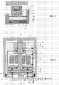
- FIG. 4 illustrates a first application of the invention for producing the joint interface structure in a SCROLL type vacuum pump.
- the operating principle of a SCROLL pump is based on the conjugation of two spiral cut profiles in a circular translational motion.
- One of the turns, mobile moves without rotation on itself relative to the fixed turn. Its center then describes a circle of radius equal to the spacing between the turns. This movement reveals an open volume allowing the suction of a fluid, then the volume closes and a transfer phase occurs on the length of the profile, which is transformed into compression, the radius of turns decreasing. Refoulement takes place at final side in the central part of the turns where the residual volume becomes minimal.
- the sealing of such a pump is axially and radially between the projecting parts, the walls, the recessed parts of the turns, the grooves.
- the sealing is done in particular by axial compensation joints intended to minimize the space that exists axially between the end of the walls and the bottom of the grooves of the two parts.
- the seal protrudes from the wall and slides over the bottom of the furrow opposite it.
- an elastomer element may be inserted between the gasket itself and the bottom of the groove to give the assembly an elasticity in the axial direction so as to press the gasket onto the counter-face independently of the positions of the turns themselves. .
- Figure 4 illustrates an application of the invention to the interface structure between the seal and the counter surface.
- the seal 10 is disposed in the bottom of the groove 11, and rubs against the smooth end surface 12 of the wall 13.
- the seal 10 is formed of a ceramic surface area produced as previously indicated by micro-arc oxidation.
- An elastomer compression portion 14 is interposed between the bottom of the groove 11 and the seal 10.
- FIG. 5 illustrates another application of the invention for producing the accidental contact zones of a turbomolecular pump.
- a molecular pump comprises a rotor 20 rotating at high speed along an axis II-II around a stator 21, the assembly being disposed in a housing 22.
- a peripheral accidental contact zone 23 must be provided between the housing 22 se deforming under the effect of external stresses and the rotor 20.
- This accidental contact zone 23 may comprise an interface structure as defined above according to the invention, with the housing 22 acting as the first mechanical part 1 , and with the rotor 20 acting as the second mechanical part 2.
- FIG. 5 also illustrates the use of the invention to establish the zones in contact during the start-up and landing phases of a gas-bearing pin of such a turbomolecular pump.
- the principle of a gas bearing pin is to establish smooth bearings and an axial stop with low clearance, a few microns, compared to a tree. Nozzles are provided in these bearings to generate a local gas pressure in the interstitial interplay between surfaces. When the spindle rotates at high speed the aerodynamic lift effect is maximum.
- the axial abutment 24 is between an abutment 25 and a lower bearing / abutment 26.
- the upper bearing 27 guides the rotor 20.
- the opposing pairs thus arranged are applications of the present invention.
- the rotating parts constitute the mechanical part 1, and the static parts constitute the mechanical part 2.
- the contact between parts is certain in the starting phase as in that of stop.
- the use of a coating suitable for friction without emission of particles is necessary.
- the aerodynamic lift is acquired only when the spindle reaches the higher speeds, even with the addition of the incoming purges which are compensated in this operation in depression by a pumping of extraction of the gas which escapes from the interstitial zones so as to limit the leak at the top of the spindle.
- the upper bearing 27 is extended by a dynamic seal 28 to introduce a maximum pressure drop between the volume of the bearing and the vacuum pump part.
- FIG. 6 there is illustrated another application of the invention for the realization of the interface structures in a SCROLL pump.
- the rotor 31 moves by rubbing axially on the stator 32.
- the one and the other constitute alternately the first mechanical part 1 or the second mechanical part 2 in the direction described in relation with FIG. 3.
- the antagonistic surfaces of play friction According to the invention, the micro-arc oxidation is completed by coating the surfaces with a resin containing solid lubricant.
- the reciprocal conformation of the lateral faces is obtained by prior running-in of the assembled parts.
- Figure 7 illustrates another application of the invention for the realization of the interface structures in a piston vacuum pump.
- the surfaces Friction antagonists are produced according to the invention by micro-arc oxidation.
Landscapes
- Chemical & Material Sciences (AREA)
- Engineering & Computer Science (AREA)
- Materials Engineering (AREA)
- Chemical Kinetics & Catalysis (AREA)
- Electrochemistry (AREA)
- Metallurgy (AREA)
- Organic Chemistry (AREA)
- General Engineering & Computer Science (AREA)
- Mechanical Engineering (AREA)
- General Chemical & Material Sciences (AREA)
- Sliding-Contact Bearings (AREA)
- Compressor (AREA)
- Applications Or Details Of Rotary Compressors (AREA)
- Rotary Pumps (AREA)
Applications Claiming Priority (1)
| Application Number | Priority Date | Filing Date | Title |
|---|---|---|---|
| FR0650815A FR2898289B1 (fr) | 2006-03-10 | 2006-03-10 | Structure d'interface entre deux pieces mecaniques en mouvement, procede pour sa realisation, et application aux pompes a vide |
Publications (1)
| Publication Number | Publication Date |
|---|---|
| EP1832753A2 true EP1832753A2 (de) | 2007-09-12 |
Family
ID=37387438
Family Applications (1)
| Application Number | Title | Priority Date | Filing Date |
|---|---|---|---|
| EP07103799A Withdrawn EP1832753A2 (de) | 2006-03-10 | 2007-03-08 | Schnittstellenstruktur zwischen zwei sich in Bewegung befindlichen mechanischen Teilen, Verfahren zu dessen Umsetzung und Anwendung in Vakuumpumpen |
Country Status (2)
| Country | Link |
|---|---|
| EP (1) | EP1832753A2 (de) |
| FR (1) | FR2898289B1 (de) |
Cited By (9)
| Publication number | Priority date | Publication date | Assignee | Title |
|---|---|---|---|---|
| CN103757679A (zh) * | 2014-01-22 | 2014-04-30 | 东风活塞轴瓦有限公司 | 一种铝合金活塞顶部微弧氧化方法 |
| US9619020B2 (en) | 2013-03-01 | 2017-04-11 | Tobii Ab | Delay warp gaze interaction |
| US9864498B2 (en) | 2013-03-13 | 2018-01-09 | Tobii Ab | Automatic scrolling based on gaze detection |
| US9952883B2 (en) | 2014-08-05 | 2018-04-24 | Tobii Ab | Dynamic determination of hardware |
| US10317995B2 (en) | 2013-11-18 | 2019-06-11 | Tobii Ab | Component determination and gaze provoked interaction |
| CN110014271A (zh) * | 2019-05-14 | 2019-07-16 | 河北工业大学 | 一种基于微弧氧化的合金室温连接方法 |
| US10558262B2 (en) | 2013-11-18 | 2020-02-11 | Tobii Ab | Component determination and gaze provoked interaction |
| US10683581B2 (en) | 2015-12-16 | 2020-06-16 | Henkel Ag & Co. Kgaa | Method for deposition of titanium-based protective coatings on aluminum |
| US20240209857A1 (en) * | 2022-12-21 | 2024-06-27 | Pfeiffer Vacuum Technology AG | Pump and method of manufacturing a sealing |
Family Cites Families (3)
| Publication number | Priority date | Publication date | Assignee | Title |
|---|---|---|---|---|
| DE4239391C2 (de) * | 1991-11-27 | 1996-11-21 | Electro Chem Eng Gmbh | Gegenstände aus Aluminium, Magnesium oder Titan mit einer mit Fluorpolymeren gefüllten Oxidkeramikschicht und Verfahren zu ihrer Herstellung |
| DE10163864A1 (de) * | 2001-12-22 | 2003-07-10 | Leybold Vakuum Gmbh | Beschichtung von Gegenständen |
| DE202004010821U1 (de) * | 2003-07-23 | 2004-12-23 | The Boc Group Plc, Windlesham | Vakuumpumpenbauteil |
-
2006
- 2006-03-10 FR FR0650815A patent/FR2898289B1/fr not_active Expired - Fee Related
-
2007
- 2007-03-08 EP EP07103799A patent/EP1832753A2/de not_active Withdrawn
Cited By (13)
| Publication number | Priority date | Publication date | Assignee | Title |
|---|---|---|---|---|
| US10545574B2 (en) | 2013-03-01 | 2020-01-28 | Tobii Ab | Determining gaze target based on facial features |
| US9619020B2 (en) | 2013-03-01 | 2017-04-11 | Tobii Ab | Delay warp gaze interaction |
| US10534526B2 (en) | 2013-03-13 | 2020-01-14 | Tobii Ab | Automatic scrolling based on gaze detection |
| US9864498B2 (en) | 2013-03-13 | 2018-01-09 | Tobii Ab | Automatic scrolling based on gaze detection |
| US10558262B2 (en) | 2013-11-18 | 2020-02-11 | Tobii Ab | Component determination and gaze provoked interaction |
| US10317995B2 (en) | 2013-11-18 | 2019-06-11 | Tobii Ab | Component determination and gaze provoked interaction |
| CN103757679B (zh) * | 2014-01-22 | 2016-05-18 | 东风活塞轴瓦有限公司 | 一种铝合金活塞顶部微弧氧化方法 |
| CN103757679A (zh) * | 2014-01-22 | 2014-04-30 | 东风活塞轴瓦有限公司 | 一种铝合金活塞顶部微弧氧化方法 |
| US9952883B2 (en) | 2014-08-05 | 2018-04-24 | Tobii Ab | Dynamic determination of hardware |
| US10683581B2 (en) | 2015-12-16 | 2020-06-16 | Henkel Ag & Co. Kgaa | Method for deposition of titanium-based protective coatings on aluminum |
| CN110014271A (zh) * | 2019-05-14 | 2019-07-16 | 河北工业大学 | 一种基于微弧氧化的合金室温连接方法 |
| CN110014271B (zh) * | 2019-05-14 | 2020-11-10 | 河北工业大学 | 一种基于微弧氧化的合金室温连接方法 |
| US20240209857A1 (en) * | 2022-12-21 | 2024-06-27 | Pfeiffer Vacuum Technology AG | Pump and method of manufacturing a sealing |
Also Published As
| Publication number | Publication date |
|---|---|
| FR2898289A1 (fr) | 2007-09-14 |
| FR2898289B1 (fr) | 2009-01-30 |
Similar Documents
| Publication | Publication Date | Title |
|---|---|---|
| EP1832753A2 (de) | Schnittstellenstruktur zwischen zwei sich in Bewegung befindlichen mechanischen Teilen, Verfahren zu dessen Umsetzung und Anwendung in Vakuumpumpen | |
| FR3008023B1 (fr) | Revetements polymeres deposes sur des substrats par des techniques de projection thermique | |
| EP3194779B1 (de) | Kompressionsvorrichtung und spiralverdichter mit solch einer kompressionsvorrichtung | |
| CN110621880B (zh) | 具有多层涂布的转子螺杆的螺杆压缩机 | |
| JP4737141B2 (ja) | 圧縮機 | |
| FR2845095A1 (fr) | Piece coulissante | |
| WO2005068840A1 (ja) | 流体機械 | |
| JP2010174902A (ja) | 圧縮機 | |
| FR2817921A1 (fr) | Compresseur et element coulissant de celui-ci | |
| CA2949729C (fr) | Raccord d'etancheite tournant haute-pression a bague continue extensible | |
| CN102037242A (zh) | 斜盘式压缩机的斜盘以及斜盘式压缩机 | |
| CN119480586A (zh) | 一种增强液态金属滑动轴承 | |
| EP2659025A1 (de) | Kolbenanordnung für alternative verdichter | |
| CN1136390C (zh) | 冷冻机用压缩机的轴承及冷冻机用压缩机 | |
| JP2004323594A (ja) | 塗料組成物及び摺動部品 | |
| JP5132711B2 (ja) | ベーン、ローリングピストン式単段型回転式の密閉形圧縮機、給湯機、および、ベーンの製造方法 | |
| JP2008280485A (ja) | 摺動部被覆用樹脂組成物 | |
| JP2009287483A (ja) | 冷媒圧縮機 | |
| JP4616140B2 (ja) | 密閉形圧縮機及び給湯機 | |
| WO2017018424A1 (ja) | 摺動部材及び摺動部材の製造方法 | |
| EP3586045B1 (de) | Bewegungsübertragungsvorrichtung für einen verbrennungsmotor | |
| JP2005133593A (ja) | 斜板式コンプレッサの斜板 | |
| WO2022209966A1 (ja) | 摺動部品 | |
| JP4813135B2 (ja) | 回転式圧縮機 | |
| EP0018265A1 (de) | Maschine, wie zum Beispiel Pumpe, wovon mindestens einige bewegliche Teile in Berührung mit Meerwasser sind |
Legal Events
| Date | Code | Title | Description |
|---|---|---|---|
| PUAI | Public reference made under article 153(3) epc to a published international application that has entered the european phase |
Free format text: ORIGINAL CODE: 0009012 |
|
| AK | Designated contracting states |
Kind code of ref document: A2 Designated state(s): AT BE BG CH CY CZ DE DK EE ES FI FR GB GR HU IE IS IT LI LT LU LV MC MT NL PL PT RO SE SI SK TR |
|
| AX | Request for extension of the european patent |
Extension state: AL BA HR MK YU |
|
| STAA | Information on the status of an ep patent application or granted ep patent |
Free format text: STATUS: THE APPLICATION IS DEEMED TO BE WITHDRAWN |
|
| RAP1 | Party data changed (applicant data changed or rights of an application transferred) |
Owner name: ALCATEL LUCENT |
|
| 18D | Application deemed to be withdrawn |
Effective date: 20121002 |