EP1832764A2 - Palier à roulement pouvant être freiné - Google Patents
Palier à roulement pouvant être freiné Download PDFInfo
- Publication number
- EP1832764A2 EP1832764A2 EP07004115A EP07004115A EP1832764A2 EP 1832764 A2 EP1832764 A2 EP 1832764A2 EP 07004115 A EP07004115 A EP 07004115A EP 07004115 A EP07004115 A EP 07004115A EP 1832764 A2 EP1832764 A2 EP 1832764A2
- Authority
- EP
- European Patent Office
- Prior art keywords
- ring
- brake
- inner ring
- receiving part
- outer ring
- Prior art date
- Legal status (The legal status is an assumption and is not a legal conclusion. Google has not performed a legal analysis and makes no representation as to the accuracy of the status listed.)
- Withdrawn
Links
Images
Classifications
-
- F—MECHANICAL ENGINEERING; LIGHTING; HEATING; WEAPONS; BLASTING
- F16—ENGINEERING ELEMENTS AND UNITS; GENERAL MEASURES FOR PRODUCING AND MAINTAINING EFFECTIVE FUNCTIONING OF MACHINES OR INSTALLATIONS; THERMAL INSULATION IN GENERAL
- F16C—SHAFTS; FLEXIBLE SHAFTS; ELEMENTS OR CRANKSHAFT MECHANISMS; ROTARY BODIES OTHER THAN GEARING ELEMENTS; BEARINGS
- F16C33/00—Parts of bearings; Special methods for making bearings or parts thereof
- F16C33/30—Parts of ball or roller bearings
-
- F—MECHANICAL ENGINEERING; LIGHTING; HEATING; WEAPONS; BLASTING
- F16—ENGINEERING ELEMENTS AND UNITS; GENERAL MEASURES FOR PRODUCING AND MAINTAINING EFFECTIVE FUNCTIONING OF MACHINES OR INSTALLATIONS; THERMAL INSULATION IN GENERAL
- F16C—SHAFTS; FLEXIBLE SHAFTS; ELEMENTS OR CRANKSHAFT MECHANISMS; ROTARY BODIES OTHER THAN GEARING ELEMENTS; BEARINGS
- F16C41/00—Other accessories, e.g. devices integrated in the bearing not relating to the bearing function as such
- F16C41/001—Integrated brakes or clutches for stopping or coupling the relatively movable parts
-
- F—MECHANICAL ENGINEERING; LIGHTING; HEATING; WEAPONS; BLASTING
- F16—ENGINEERING ELEMENTS AND UNITS; GENERAL MEASURES FOR PRODUCING AND MAINTAINING EFFECTIVE FUNCTIONING OF MACHINES OR INSTALLATIONS; THERMAL INSULATION IN GENERAL
- F16D—COUPLINGS FOR TRANSMITTING ROTATION; CLUTCHES; BRAKES
- F16D37/00—Clutches in which the drive is transmitted through a medium consisting of small particles, e.g. centrifugally speed-responsive
- F16D37/02—Clutches in which the drive is transmitted through a medium consisting of small particles, e.g. centrifugally speed-responsive the particles being magnetisable
-
- F—MECHANICAL ENGINEERING; LIGHTING; HEATING; WEAPONS; BLASTING
- F16—ENGINEERING ELEMENTS AND UNITS; GENERAL MEASURES FOR PRODUCING AND MAINTAINING EFFECTIVE FUNCTIONING OF MACHINES OR INSTALLATIONS; THERMAL INSULATION IN GENERAL
- F16D—COUPLINGS FOR TRANSMITTING ROTATION; CLUTCHES; BRAKES
- F16D57/00—Liquid-resistance brakes; Brakes using the internal friction of fluids or fluid-like media, e.g. powders
- F16D57/002—Liquid-resistance brakes; Brakes using the internal friction of fluids or fluid-like media, e.g. powders comprising a medium with electrically or magnetically controlled internal friction, e.g. electrorheological fluid, magnetic powder
-
- F—MECHANICAL ENGINEERING; LIGHTING; HEATING; WEAPONS; BLASTING
- F16—ENGINEERING ELEMENTS AND UNITS; GENERAL MEASURES FOR PRODUCING AND MAINTAINING EFFECTIVE FUNCTIONING OF MACHINES OR INSTALLATIONS; THERMAL INSULATION IN GENERAL
- F16C—SHAFTS; FLEXIBLE SHAFTS; ELEMENTS OR CRANKSHAFT MECHANISMS; ROTARY BODIES OTHER THAN GEARING ELEMENTS; BEARINGS
- F16C2210/00—Fluids
- F16C2210/02—Fluids defined by their properties
- F16C2210/06—Fluids defined by their properties magnetic fluids
-
- F—MECHANICAL ENGINEERING; LIGHTING; HEATING; WEAPONS; BLASTING
- F16—ENGINEERING ELEMENTS AND UNITS; GENERAL MEASURES FOR PRODUCING AND MAINTAINING EFFECTIVE FUNCTIONING OF MACHINES OR INSTALLATIONS; THERMAL INSULATION IN GENERAL
- F16D—COUPLINGS FOR TRANSMITTING ROTATION; CLUTCHES; BRAKES
- F16D37/00—Clutches in which the drive is transmitted through a medium consisting of small particles, e.g. centrifugally speed-responsive
- F16D2037/005—Clutches in which the drive is transmitted through a medium consisting of small particles, e.g. centrifugally speed-responsive characterised by a single substantially radial gap in which the fluid or medium consisting of small particles is arranged
Definitions
- the present invention relates to a bearing and more particularly to a rolling bearing.
- braked bearings in many applications. For example, it is legally required for machines such as circular saws that they come to a standstill after use within a certain time.
- a braking effect Especially with shaft assemblies, such a need exists for a braking effect. From the prior art, various possibilities are known to produce such a braking effect.
- friction brakes are known which generate the braking effect using brake disks or brake drums.
- Such friction brakes are sensitive to lubricants and also susceptible to wear.
- an external component and a large space requirement is needed.
- the desired braking force is difficult to adjust or dose and possibly loud noise generated by the braking process.
- the present invention is therefore based on the object to provide a brakable rolling bearing available, which requires only small space.
- the braking device for the bearing should be integrated directly in this, without affecting the actual storage function.
- the braking device and the bearing should form a unit, so that no complex environment constructions for example, the derivation of the braking forces are necessary.
- the bearing according to the invention has an inner ring, and an outer ring.
- a magnetic element is provided, which is connected either with the inner ring or with the outer ring substantially rotationally fixed.
- a medium is provided in at least one region between the inner ring and the outer ring, whose viscosity changes as a function of a magnetic field passing through it.
- the magnetic element may be provided on a stationary inner or outer ring or on a moving inner or outer ring.
- the medium is a liquid, and more preferably a magnetorheological fluid.
- Magnetorheological fluids have the property that they can change their viscosity by several orders of magnitude depending on a magnetic field passing through them.
- the term "magnetorheological fluid” refers to fluids that, like ferrofluids, react to a magnetic field but, in contrast to it, solidify.
- magnetorheological fluids consist of a suspension of micrometer-sized magnetic particles one to three orders of magnitude larger than the particles of ferrofluids.
- the relatively large particles of magnetorheological fluids form chains when a magnetic field is applied. This increases the viscosity of the MRF and may even solidify it if an applied compressive force is not large enough to break the chains.
- the magnetic element is an electromagnet.
- the advantage of this embodiment is that the solenoid and thus the braking effect can be switched on or off.
- the braking force is very finely adjustable via the magnetic field applied by the magnetic element.
- a very soft braking behavior can be achieved by the fluid-induced frictional engagement between the moving parts.
- the brake device does not squeak.
- the solenoid is adjustable and thus the braking force adjustable.
- the magnetic element is arranged on the outer ring and on the inner ring a brake ring, which consists of a ferromagnetic material.
- This embodiment is particularly suitable for bearing variants in which the outer ring is opposite to the environment and the inner ring rotates with respect to the outer ring and thus also with respect to the environment.
- This brake ring is preferably rotatably connected to the inner ring.
- a magnetic field By under-current-setting of the electromagnet can be generated between this and the ferromagnetic ring, a magnetic field. As mentioned above, this magnetic field increases the viscosity of the magnetorheological fluid and thus achieves a braking effect controllable by the magnitude of the magnetic field.
- the magnetic element is arranged on the inner ring and on the outer ring a brake ring of a ferromagnetic material.
- This embodiment is particularly suitable for those rolling bearings in which the inner ring is stationary relative to the environment and the outer ring moves relative thereto.
- a gap is formed between the magnetic element and the brake ring, in which the medium is arranged.
- very high magnetic fields between the magnetic element and the brake ring can be generated.
- the brake ring is substantially non-rotatably connected to the inner ring or the outer ring.
- a plurality of magnetic elements is provided. These magnetic elements are preferably provided uniformly in the circumferential direction of the rolling bearing.
- the individual magnetic elements can be arranged both axially and radially, as well as in a different direction with respect to the rolling bearing.
- a radial direction is understood to mean that the poles of the magnetic element lie on a straight line which runs essentially radially with respect to the rolling bearing.
- the poles are arranged on a straight line which is substantially parallel to the rolling bearing axis.
- the brake ring is designed to be substantially cylindrical on the surface facing the magnetic element. This means that the brake ring is made smooth here. However, it would also be possible to perform the brake ring with a toothing (for example, the encoder ring at a speed sensor bearing).
- a first receiving part device is arranged on the outer ring and on the inner ring a second receiving part means and the first and the second receiving part means form a receiving space for the medium. This means that the medium is limited spatially by the two receiving part devices, which together form a preferably liquid-tight receiving space.
- At least one receiving part device is formed integrally with the outer ring or the inner ring.
- at least one receiving part device is a housing part connected to the outer ring or inner ring.
- a receiving part device formed integrally with a ring and the other receiving part device is a connected to the other ring housing part.
- One of the receiving part devices is preferably even sections executed as a brake ring.
- this receiving part device preferably has an annular section made of a ferromagnetic material.
- the entire receiving part device may be made of a ferromagnetic material.
- the invention described above can be used in all types of bearings, such as in rolling or sliding bearings.
- the present invention is directed to the use of a magnetorheological fluid for bearings, and more particularly for rolling bearings.
- suitable magnetorheological fluids the viscosity of which strongly depends on a magnetic field applied to them, in a special way to selectively slow down a camp or to bring in preferred rotational positions to a standstill.
- the present invention is further directed to a brake device, in particular for a rolling bearing.
- This brake device has a first brake element and a second relative to this first brake element movable brake element. Between the first brake element and the second brake element, a magnetorheological fluid is arranged and at least one of the brake elements is a magnetic element. Preferably, a body of ferromagnetic material is provided on the respective other brake element. As mentioned above, the application of a magnetic field to the magnetorheological fluid increases the viscosity thereof. In this way, the movement of the first brake element relative to the second brake element can be braked and thus a delay occur.
- the brake elements also serve as receiving part devices, which - optionally with other elements - form a receiving space for the magnetorheological fluid.
- This braking device can, as mentioned above, for example, be arranged on a rolling bearing. However, it is also possible that the brake elements perform an axial movement against each other and this movement is to be braked.
- the first brake element and the second brake element is a substantially liquid-tight Formed receiving space in which the magnetorheological fluid is arranged.
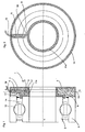
- This rolling bearing 1 shows an inventive rolling bearing 1.
- This rolling bearing 1 has an inner ring 2 and an outer ring 3.
- the outer ring 3 with a plurality of rolling elements 13 which are arranged in a rolling element cage 14, rotatably mounted relative to the inner ring 2. More specifically, in this embodiment, the outer ring is silent to the environment.
- a first receiving part means 15 is arranged in the form of an additional housing 15.
- this housing is comparable to a sensor housing in speed sensor bearings.
- the first receiving part device 15 is rotatably connected to the outer ring 3.
- a second receiving part device 11 is arranged in the form of a brake ring and rotatably connected to the inner ring 2. Again, it would be possible in a further embodiment, to integrate the second receiving part device 11 as a rotating surface directly into the inner ring 2.
- the second receiving part device 11 or the brake ring is ideally made of a ferromagnetic material. However, it would also be possible to carry out the second receiving part device 11 and the brake ring as separate but interconnected elements.
- the first receiving part device 15 is closed with a cover 7 and designed so that, together with the first receiving part means 15, the second receiving part means 11 and two seals 17, a liquid-tight space 4 results, which is filled with a magnetorheological fluid 6.
- a magnetic element 5 is mounted in the form of a magnetic coil, which can be powered by a cable 16 with power. Between the magnetic element 5 and the second receiving part device 11 so a gap 9, in which magnetorheological fluid 6 is formed. If the magnetic element flows through an electric current, a magnetic field is formed, which passes through the gap 9 and there raises the viscosity of the magnetorheological fluid 6. Due to the thus increased friction, the torque is transmitted from the second receiving part device 11 to the magnetic element 5 and thus the first receiving part device 15 and thus brakes the inner ring 2 of the bearing.
- a plurality of magnetic elements 5 could be arranged in the circumferential direction about the axis of the rolling bearing.
- magnetic elements could be arranged on the lid 7, for example be and extend in the longitudinal direction of the rolling bearing, more precisely in the direction of the portion 11a of the second receiving part device. In this case, a magnetic field would be generated in the direction of the bearing axis L.
- the second receiving part device 11 or the brake ring as a sheet metal part. In the embodiment shown in Fig. 1, the portion 11a simultaneously performs the function of the brake ring.
- the camp is carried out passively, that is, that the magnetic field is not introduced via electromagnets, but via permanent magnets.
- permanent magnets could be mounted externally or in specially provided brackets in stock. It would also be possible to permanently mount such permanent magnets and turn their magnetic flux in the gap 9 on and off, for example via movable plates.
- the resulting component of the two receiving part devices 11 and 15 and the magnetic element 5, could also be arranged on other with respect to each other rotating bodies and is therefore not limited to be mounted on a rolling bearing.
- dampen longitudinal movement such as movement of a piston relative to a cylinder.
- damping mechanisms or spring damper could be developed, the damping effect of which can be varied depending on a applied to the liquid magnetic field.
- Possible applications of the invention are especially those in which an external brake would blow up the available space or those in which must be braked in heavily lubricating environment, which would lead in the case of a conventional braking device, for example, that about a brake disc would slip through. Also, applications in which the braking should take place as quietly as possible, are suitable for the invention described here.
- the braking device according to the invention could also be used for damping torsional vibrations.
- FIG. 2 shows a plan view of the bearing from FIG. 1. It can be seen that a gap 9 is formed between the second receiving part device 11 and the magnetic element 5 or the surface 5 a of the magnetic element 5. By switching on the magnetic element 5 or the application of electrical current, the viscosity of the magnetorheological fluid 6 is increased in particular in the gap 9 and thus the braking effect on the entire camp.
Landscapes
- Engineering & Computer Science (AREA)
- General Engineering & Computer Science (AREA)
- Mechanical Engineering (AREA)
- Rolling Contact Bearings (AREA)
- Vibration Prevention Devices (AREA)
Applications Claiming Priority (1)
| Application Number | Priority Date | Filing Date | Title |
|---|---|---|---|
| DE102006010618A DE102006010618A1 (de) | 2006-03-08 | 2006-03-08 | Bremsbares Wälzlager |
Publications (2)
| Publication Number | Publication Date |
|---|---|
| EP1832764A2 true EP1832764A2 (fr) | 2007-09-12 |
| EP1832764A3 EP1832764A3 (fr) | 2008-07-09 |
Family
ID=38093469
Family Applications (1)
| Application Number | Title | Priority Date | Filing Date |
|---|---|---|---|
| EP07004115A Withdrawn EP1832764A3 (fr) | 2006-03-08 | 2007-02-28 | Palier à roulement pouvant être freiné |
Country Status (2)
| Country | Link |
|---|---|
| EP (1) | EP1832764A3 (fr) |
| DE (1) | DE102006010618A1 (fr) |
Cited By (2)
| Publication number | Priority date | Publication date | Assignee | Title |
|---|---|---|---|---|
| WO2008095460A1 (fr) * | 2007-02-07 | 2008-08-14 | Schaeffler Kg | Palier à roulement pouvant être freiné |
| WO2011089068A1 (fr) * | 2010-01-21 | 2011-07-28 | Schaeffler Technologies Gmbh & Co. Kg | Palier freinable |
Families Citing this family (2)
| Publication number | Priority date | Publication date | Assignee | Title |
|---|---|---|---|---|
| DE102007003470A1 (de) * | 2007-01-24 | 2008-07-31 | Schaeffler Kg | Lagereinheit mit einstellbarem Reibmoment zur Bereitstellung einer Bremsfunktion |
| DE202012008390U1 (de) * | 2012-06-16 | 2013-09-17 | Intorq Gmbh & Co. Kg | Elektromagnetisch betätigbare Bremse |
Family Cites Families (11)
| Publication number | Priority date | Publication date | Assignee | Title |
|---|---|---|---|---|
| DE4223256A1 (de) * | 1992-07-15 | 1994-01-20 | Schaeffler Waelzlager Kg | Schwingungdämpfende Lagerstellmutter |
| DE4227366A1 (de) * | 1992-08-19 | 1994-02-24 | Schaeffler Waelzlager Kg | Lagerung mit Dämpfung |
| US5452957A (en) * | 1994-11-22 | 1995-09-26 | Dana Corporation | Center bearing assembly including support member containing rheological fluid |
| US5900184A (en) * | 1995-10-18 | 1999-05-04 | Lord Corporation | Method and magnetorheological fluid formulations for increasing the output of a magnetorheological fluid device |
| DE19735897A1 (de) * | 1997-08-19 | 1999-02-25 | Bayer Ag | Kupplung |
| US5902048A (en) * | 1997-12-19 | 1999-05-11 | Dana Corporation | Center bearing assembly having shear plate |
| EP1350972A3 (fr) * | 2002-04-04 | 2004-06-23 | Dana Corporation | Ensemble de palier intermédiaire pour arbre cardan avec un support contenant de fluide rhéologique |
| US6899196B2 (en) * | 2003-10-16 | 2005-05-31 | Visteon Global Technologies, Inc. | Driver interface system for steer-by-wire system |
| DE102005003593A1 (de) * | 2004-01-29 | 2005-09-15 | Preh Gmbh | Programmierbarer Drehmomentgeber mit Federelement |
| DE102004009906B3 (de) * | 2004-02-26 | 2005-07-28 | Nacam Deutschland Gmbh | Wälzlager mit einstellbarer Kraftübertragung |
| DE102004024226B4 (de) * | 2004-05-15 | 2008-10-09 | FIP Forschungsinstitut für Produktionstechnik GmbH Braunschweig | Vorrichtung zum Übertragen von Kräften oder Momenten mit einem Arbeitsraum |
-
2006
- 2006-03-08 DE DE102006010618A patent/DE102006010618A1/de not_active Withdrawn
-
2007
- 2007-02-28 EP EP07004115A patent/EP1832764A3/fr not_active Withdrawn
Cited By (2)
| Publication number | Priority date | Publication date | Assignee | Title |
|---|---|---|---|---|
| WO2008095460A1 (fr) * | 2007-02-07 | 2008-08-14 | Schaeffler Kg | Palier à roulement pouvant être freiné |
| WO2011089068A1 (fr) * | 2010-01-21 | 2011-07-28 | Schaeffler Technologies Gmbh & Co. Kg | Palier freinable |
Also Published As
| Publication number | Publication date |
|---|---|
| DE102006010618A1 (de) | 2007-09-13 |
| EP1832764A3 (fr) | 2008-07-09 |
Similar Documents
| Publication | Publication Date | Title |
|---|---|---|
| EP3737873B1 (fr) | Dispositif de freinage magnétorhéologique | |
| DE102012017423B4 (de) | Magnetorheologische Übertragungseinrichtung | |
| EP3625651B1 (fr) | Dispositif de commande haptique pour un véhicule a moteur | |
| EP3102851B1 (fr) | Actionneur magnéto-rhéologique présentant une broche filetée entraînée en rotation, et couplage présentant un actionneur | |
| DE112016005194B4 (de) | Aktor | |
| DE102008011858B4 (de) | Vorrichtung zur Dämpfung einer Drehbewegung | |
| DE102016124117B4 (de) | Türkomponente mit einem steuerbaren Drehdämpfer | |
| DE102013204436A1 (de) | Antrieb für eine Transportvorrichtung, Satz von Antrieben und Verfahren zum Antreiben einer Transportvorrichtung | |
| DE102011010153B4 (de) | Hydrodynamische Komponente | |
| EP2961624A1 (fr) | Amortisseur de rotation pour véhicule automobile | |
| DE102016124115A1 (de) | Drehdämpfer | |
| DE102019135026A1 (de) | Gerätekomponente mit einer magnetorheologischen Bremseinrichtung | |
| DE102007051229A1 (de) | Wälzlager mit einer Bremseinrichtung | |
| DE102020117087A1 (de) | Haptische Bedieneinrichtung mit einer magnetorheologischen Bremseinrichtung und einem drehbaren Bedienteil für Fahrzeuge | |
| DE102019135027B3 (de) | Gerätekomponente für eine magnetorheologische Bremseinrichtung mit Temperaturausgleich | |
| DE102006026123B3 (de) | Verfahren zum Dämpfen von Bewegungen eines um eine Rotorachse rotierenden Rotors und Lager zur Durchführung des Verfahrens | |
| EP1832764A2 (fr) | Palier à roulement pouvant être freiné | |
| DE102007006015A1 (de) | Bremsbares Wälzlager | |
| EP1832763A2 (fr) | Palier avec une position d'arrêt préféré | |
| DE102020117080A1 (de) | Haptische Bedieneinrichtung mit einer magnetorheologischen Bremseinrichtung und einem drehbaren Bedienteil | |
| DE102015201016A1 (de) | Kupplung mit magnetorheologischen Aktor auf einer Antriebswelle | |
| EP1210530B1 (fr) | Piece d'ecartement pour reducteur de positionnement axial | |
| DE202011001482U1 (de) | Trommelbremse | |
| DE102013215259A1 (de) | Radialflexibles Wälzlager | |
| DE102014217535A1 (de) | Magnetorheologischer Aktor und Kupplung mit solchem Aktor |
Legal Events
| Date | Code | Title | Description |
|---|---|---|---|
| PUAI | Public reference made under article 153(3) epc to a published international application that has entered the european phase |
Free format text: ORIGINAL CODE: 0009012 |
|
| AK | Designated contracting states |
Kind code of ref document: A2 Designated state(s): AT BE BG CH CY CZ DE DK EE ES FI FR GB GR HU IE IS IT LI LT LU LV MC NL PL PT RO SE SI SK TR |
|
| AX | Request for extension of the european patent |
Extension state: AL BA HR MK YU |
|
| PUAL | Search report despatched |
Free format text: ORIGINAL CODE: 0009013 |
|
| AK | Designated contracting states |
Kind code of ref document: A3 Designated state(s): AT BE BG CH CY CZ DE DK EE ES FI FR GB GR HU IE IS IT LI LT LU LV MC NL PL PT RO SE SI SK TR |
|
| AX | Request for extension of the european patent |
Extension state: AL BA HR MK RS |
|
| RIC1 | Information provided on ipc code assigned before grant |
Ipc: F16D 37/02 20060101ALI20080530BHEP Ipc: F16D 57/02 20060101ALI20080530BHEP Ipc: F16C 41/00 20060101ALI20080530BHEP Ipc: F16C 33/30 20060101AFI20070613BHEP |
|
| 17P | Request for examination filed |
Effective date: 20090109 |
|
| 17Q | First examination report despatched |
Effective date: 20090212 |
|
| AKX | Designation fees paid |
Designated state(s): AT BE BG CH CY CZ DE DK EE ES FI FR GB GR HU IE IS IT LI LT LU LV MC NL PL PT RO SE SI SK TR |
|
| STAA | Information on the status of an ep patent application or granted ep patent |
Free format text: STATUS: THE APPLICATION IS DEEMED TO BE WITHDRAWN |
|
| 18D | Application deemed to be withdrawn |
Effective date: 20090623 |
|
| P01 | Opt-out of the competence of the unified patent court (upc) registered |
Effective date: 20230523 |