EP1832786A1 - Getriebeschaltgabel - Google Patents
Getriebeschaltgabel Download PDFInfo
- Publication number
- EP1832786A1 EP1832786A1 EP06425148A EP06425148A EP1832786A1 EP 1832786 A1 EP1832786 A1 EP 1832786A1 EP 06425148 A EP06425148 A EP 06425148A EP 06425148 A EP06425148 A EP 06425148A EP 1832786 A1 EP1832786 A1 EP 1832786A1
- Authority
- EP
- European Patent Office
- Prior art keywords
- fork
- prongs
- support portion
- fork according
- stationary rod
- Prior art date
- Legal status (The legal status is an assumption and is not a legal conclusion. Google has not performed a legal analysis and makes no representation as to the accuracy of the status listed.)
- Granted
Links
Images



Classifications
-
- F—MECHANICAL ENGINEERING; LIGHTING; HEATING; WEAPONS; BLASTING
- F16—ENGINEERING ELEMENTS AND UNITS; GENERAL MEASURES FOR PRODUCING AND MAINTAINING EFFECTIVE FUNCTIONING OF MACHINES OR INSTALLATIONS; THERMAL INSULATION IN GENERAL
- F16H—GEARING
- F16H63/00—Control outputs from the control unit to change-speed- or reversing-gearings for conveying rotary motion or to other devices than the final output mechanism
- F16H63/02—Final output mechanisms therefor; Actuating means for the final output mechanisms
- F16H63/30—Constructional features of the final output mechanisms
- F16H63/32—Gear shift yokes, e.g. shift forks
-
- F—MECHANICAL ENGINEERING; LIGHTING; HEATING; WEAPONS; BLASTING
- F16—ENGINEERING ELEMENTS AND UNITS; GENERAL MEASURES FOR PRODUCING AND MAINTAINING EFFECTIVE FUNCTIONING OF MACHINES OR INSTALLATIONS; THERMAL INSULATION IN GENERAL
- F16H—GEARING
- F16H63/00—Control outputs from the control unit to change-speed- or reversing-gearings for conveying rotary motion or to other devices than the final output mechanism
- F16H63/02—Final output mechanisms therefor; Actuating means for the final output mechanisms
- F16H63/30—Constructional features of the final output mechanisms
- F16H63/3069—Interrelationship between two or more final output mechanisms
- F16H2063/3073—Interrelationship between two or more final output mechanisms final output mechanisms mounted on a single shaft
-
- F—MECHANICAL ENGINEERING; LIGHTING; HEATING; WEAPONS; BLASTING
- F16—ENGINEERING ELEMENTS AND UNITS; GENERAL MEASURES FOR PRODUCING AND MAINTAINING EFFECTIVE FUNCTIONING OF MACHINES OR INSTALLATIONS; THERMAL INSULATION IN GENERAL
- F16H—GEARING
- F16H63/00—Control outputs from the control unit to change-speed- or reversing-gearings for conveying rotary motion or to other devices than the final output mechanism
- F16H63/02—Final output mechanisms therefor; Actuating means for the final output mechanisms
- F16H63/30—Constructional features of the final output mechanisms
- F16H63/32—Gear shift yokes, e.g. shift forks
- F16H2063/324—Gear shift yokes, e.g. shift forks characterised by slide shoes, or similar means to transfer shift force to sleeve
-
- F—MECHANICAL ENGINEERING; LIGHTING; HEATING; WEAPONS; BLASTING
- F16—ENGINEERING ELEMENTS AND UNITS; GENERAL MEASURES FOR PRODUCING AND MAINTAINING EFFECTIVE FUNCTIONING OF MACHINES OR INSTALLATIONS; THERMAL INSULATION IN GENERAL
- F16H—GEARING
- F16H63/00—Control outputs from the control unit to change-speed- or reversing-gearings for conveying rotary motion or to other devices than the final output mechanism
- F16H63/02—Final output mechanisms therefor; Actuating means for the final output mechanisms
- F16H63/30—Constructional features of the final output mechanisms
- F16H63/32—Gear shift yokes, e.g. shift forks
- F16H2063/327—Gear shift yokes, e.g. shift forks essentially made of sheet metal
-
- F—MECHANICAL ENGINEERING; LIGHTING; HEATING; WEAPONS; BLASTING
- F16—ENGINEERING ELEMENTS AND UNITS; GENERAL MEASURES FOR PRODUCING AND MAINTAINING EFFECTIVE FUNCTIONING OF MACHINES OR INSTALLATIONS; THERMAL INSULATION IN GENERAL
- F16H—GEARING
- F16H63/00—Control outputs from the control unit to change-speed- or reversing-gearings for conveying rotary motion or to other devices than the final output mechanism
- F16H63/02—Final output mechanisms therefor; Actuating means for the final output mechanisms
- F16H63/30—Constructional features of the final output mechanisms
- F16H63/3069—Interrelationship between two or more final output mechanisms
-
- Y—GENERAL TAGGING OF NEW TECHNOLOGICAL DEVELOPMENTS; GENERAL TAGGING OF CROSS-SECTIONAL TECHNOLOGIES SPANNING OVER SEVERAL SECTIONS OF THE IPC; TECHNICAL SUBJECTS COVERED BY FORMER USPC CROSS-REFERENCE ART COLLECTIONS [XRACs] AND DIGESTS
- Y10—TECHNICAL SUBJECTS COVERED BY FORMER USPC
- Y10T—TECHNICAL SUBJECTS COVERED BY FORMER US CLASSIFICATION
- Y10T74/00—Machine element or mechanism
- Y10T74/20—Control lever and linkage systems
- Y10T74/20012—Multiple controlled elements
- Y10T74/20018—Transmission control
- Y10T74/20177—Particular element [e.g., shift fork, template, etc.]
- Y10T74/20183—Shift fork structure
Definitions
- the present invention relates to a gear shift fork for a gearbox with discrete gear ratios for a motor vehicle.
- the invention relates to a gear shift fork comprising a support portion intended to be slidably mounted on a stationary rod, a pair of prongs which extend from the support portion and form at their distal ends respective finger portions adapted to act on a sliding coupling sleeve of the gearbox, and an actuating nose by means of which the fork is caused to slide along the stationary rod for engaging the desired gear.
- longitudinal is used to indicate a direction parallel to the axis of the shafts of the gearbox, that is, a direction parallel to the stationary rods on which the gear shift forks are slidably mounted
- transverse is used to indicate any direction perpendicular to the above-mentioned longitudinal direction
- a gear shift fork for a motor-vehicle gearbox with discrete gear ratios is generally indicated 10 and basically comprises a sheet-metal body 12, which according to a first preferred embodiment of the invention forms integrally a support portion 14 and a pair of prongs 16 projecting from opposite sides of the support portion 14, and an actuating nose 18 which is formed as a separate component from the sheet-metal body 12 and securely connected thereto.
- the support portion 14 includes a central plate portion 19, which in the condition in which it is mounted on the respective stationary rod (not shown in Figures 1 and 2) lies in plane parallel to the axis of the rod and which preferably has a rectangular shape elongated in the longitudinal direction, and a pair of ears 22 which are arranged at right angles to the central plate portion 19.
- the ears 22 have respective coaxial holes 24 defining seats for guiding the sliding movement of the fork 10 along the rod.
- one of the two ears 22 is disposed at a greater distance from the prongs 16 than the other ear.
- the support portion 14 also includes an appendage 20 which extends longitudinally from the central plate portion 19 and forms at its opposite end on eof the two ears 22.
- the support portion 14 is disposed in a non-symmetric position with respect to a plane of symmetry of the two prongs 16 perpendicular to the axis of the stationary rod.
- the other ear 22 could be formed at the end of a second appendage extending from the central plate portion on the opposite side to the first appendage 20.
- the holes 24 formed in the ears 22 are advantageously provided with respective antifriction and wearproof bushes 26.
- the bushes 26 are preferably produced by plastics overmoulding so as to meet the required dimensional and geometric tolerances without the need of performing additional machining operations on the body 12.
- the prongs 16 extend transversely from the central plate portion 19, the one directly from one of the two longitudinal sides thereof and the other from a bridge-like portion 28 (which can be better seen in Figures 3 and 4) bent with respect to the central plate portion 19.
- the bridge-like portion 28 is welded by means of a weld bead 30 to a tab 32 extending laterally from one of the two ears 22.
- the two prongs 16 are made as plate-like elongated elements, which extend in length on a transverse plane, that is, perpendicularly to the direction along which the fork slides, and in width along a parallel direction top the direction along which the fork slides, so as to have a high bending stiffness and hence to limit the deformations brought about by the actuation forces.
- the width of the prongs 16 reduces progressively from the proximal ends thereof (that is, from the ends facing the support portion 14) to distal ends thereof (that is, the ends opposite to the support portion 14). These latter have a finger-like configuration suitable for acting on a sliding coupling sleeve (not shown) arranged to engage either one or two gears.
- the finger-like ends of the prongs 16 are advantageously provided with an antifriction plastics coating 34, preferably made by overmoulding.
- the prongs 16 In their proximal portions, the prongs 16 have respective slots 36 (Figure 2), one of which is used for the fitting of the actuating nose 18.
- the two slots 36 are formed in symmetric positions relative to the finger-like ends of the prongs 16, thereby allowing the actuating nose 18 to be fitted in either one of the slots depending on the orientation of the fork 10.
- the actuating nose 18 is provided with an antifriction plastics coating 35, made by overmoulding, in the nose portion surrounding a recess 37 intended for engaging a special control member (not shown), such as for example a finger-like member carried by the lever of the control shaft of the gearbox.
- the body of the body can be easily manufactured as a single piece by blanking and bending and can therefore be produced at a low cost.
- the support portion is arranged asymmetrically relative to a plane of symmetry of the two prongs perpendicular to the axis of the stationary rod and is configured so as to enable a set of two partially overlapped forks to be mounted on the same stationary rod.
- Figure 3 illustrates an example of arrangement of the shift forks which can be used both in a manual gearbox having six forward gears and one rearward gear and in the robotized gearbox derived therefrom.
- four shift forks indicated 10a, 10b, 10c and 10d, are provided, which are arranged in sets of two forks on a pair of stationary rods 38 and 40 parallel to the axes of the input shaft and of the outer shafts of the gearbox (not shown).
- a first shift fork 10a for the first and second gears and a second shift fork 10b for the fifth and sixth gears are slidably arranged on the rod 38, whereas a third shift fork 10c for the third and fourth gears and a fourth shift fork 10d for the rear gear are slidably arranged on the rod 40.
- the parts and components associated to the four forks are indicated by the same reference numerals as those used in Figures 1 and 2, with the addition of the letter a, b, c or d depending on those parts or components belonging or being associated to the fork 10a, 10b, 10c or 10d, respectively.
- the bodies 12a-12d of the forks 10a-10d are identical to one another.
- the only difference between the various forks is given by the actuating noses 18a-18d. Since this arrangement is associated to a single-clutch gearbox, either manual or robotized, the actuating noses 18a-18d are arranged on a single transverse shift plane.
- the forks are conveniently mounted in pairs on the same rod in a mirror-like manner, that is, with the prongs 16a-16d arranged on longitudinally opposite sides and with the appendages pointing to longitudinally facing sides.
- the appendage 20a-20d of a fork is arranged under the bridge-like portion 28a-28b of the other fork and can thus slide relative thereto. It is therefore possible to limit the axial size of the sets of forks without the need of reducing the distance between the guide seats on the rod.
- the invention thus provides an optimal compromise between the opposite requirements for limitation of the axial size and for resistance against the tipping and jamming of the forks during actuation.
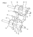
- Figure 4 illustrates on the other hand an example of arrangement of the shift forks which can be used both in a double-clutch gearbox having six forward gears and one rearward gear and in a robotized gearbox derived therefrom.
- shift forks 10a, 10b, 10c and 10d arranged in sets of two forks on a pair of stationary rods 38 and 40. More in detail, a first fork 10a for the first and fifth gears and a second fork 10b for the sixth gear are slidably arranged on the rod 38, while a third fork 10c for the second and fourth gears and a fourth fork 10d for the third and rear gears are slidably arranged on the rod 40.
- the actuating noses are arranged on two different transverse shift planes, namely on a first plane associated to the even gears (actuating noses 18b and 18c) and a second plane associated to the odd gears and to the rear gear (actuating noses 18a and 18d).
- first plane associated to the even gears
- second plane associated to the odd gears and to the rear gear
- the forks might also be arranged singularly, rather than in sets of two forks. Moreover, the forks might be all arranged, either singularly or in sets of two forks, on one stationary rod or on several stationary rods.
- a gear shift fork 110 for a motor-vehicle gearbox with discrete gear ratios differs from the first embodiment described above substantially only in that the body of the fork is made in this case in two separate pieces, instead of a single piece.
- the body of the shift fork 110 now indicated 112, comprises in fact a first sheet metal piece forming a support portion 114 and a second sheet metal piece forming a pair of prongs 116, firmly secured to one another, for example by welding.
- the shift fork 110 comprises also in this case an actuating nose 118 (shown in Figure 5 only) inserted and fixed in one of the two slots 136 symmetrically disposed relative to a finger-like end of the prongs 116.
- the support portion 114 includes a central plate portion 119, having preferably a rectangular shape elongated in the longitudinal direction and laying, in the mounted condition on the respective stationary rod (not shown), in a plane parallel to the axis of the rod, and a pair of ears 122 arranged at a right angle to the central plate portion 119.
- the ears 122 have respective coaxial holes 124 defining guide seats for the sliding movement of the fork 110 along the rod.
- one of the two ears 122 is arranged farther from the prongs 116 than the other ear, that is, the support portion 114 is not symmetrically arranged relative to a plane of symmetry of the prongs 116 perpendicular to the axis of the stationary rod. It is therefore possible to mount on the same stationary rod a set of two forks arranged so as to partially overlap, as shown in Figures 3 and 4.
- this second embodiment offers all the advantages listed above in connection with the first embodiment. Moreover, since the support portion and the prongs are formed by two separate sheet metal pieces, which are obtained preferably by blanking and are then secured to each other, it is possible to properly vary both the material and the thickness of the two pieces so as to optimize the mass, the size and the mechanical strength of the shift fork. Moreover, the scrap produced during the blanking operation is greatly reduced in comparison with the single-piece configuration of the fork body.
Landscapes
- Engineering & Computer Science (AREA)
- General Engineering & Computer Science (AREA)
- Mechanical Engineering (AREA)
- Gear-Shifting Mechanisms (AREA)
- Mechanical Operated Clutches (AREA)
Priority Applications (6)
| Application Number | Priority Date | Filing Date | Title |
|---|---|---|---|
| DE602006000491T DE602006000491T2 (de) | 2006-03-06 | 2006-03-06 | Getriebeschaltgabel |
| EP06425148A EP1832786B1 (de) | 2006-03-06 | 2006-03-06 | Getriebeschaltgabel |
| ES06425148T ES2301151T3 (es) | 2006-03-06 | 2006-03-06 | Horquilla de cambio de velocidades. |
| AT06425148T ATE384895T1 (de) | 2006-03-06 | 2006-03-06 | Getriebeschaltgabel |
| US11/612,925 US20070209466A1 (en) | 2006-03-06 | 2006-12-19 | Gear shift fork for a gearbox with discrete gear ratios |
| CN2006101562478A CN101033797B (zh) | 2006-03-06 | 2006-12-27 | 用于具有离散传动比的变速箱的换档拨叉 |
Applications Claiming Priority (1)
| Application Number | Priority Date | Filing Date | Title |
|---|---|---|---|
| EP06425148A EP1832786B1 (de) | 2006-03-06 | 2006-03-06 | Getriebeschaltgabel |
Publications (2)
| Publication Number | Publication Date |
|---|---|
| EP1832786A1 true EP1832786A1 (de) | 2007-09-12 |
| EP1832786B1 EP1832786B1 (de) | 2008-01-23 |
Family
ID=36753446
Family Applications (1)
| Application Number | Title | Priority Date | Filing Date |
|---|---|---|---|
| EP06425148A Expired - Lifetime EP1832786B1 (de) | 2006-03-06 | 2006-03-06 | Getriebeschaltgabel |
Country Status (6)
| Country | Link |
|---|---|
| US (1) | US20070209466A1 (de) |
| EP (1) | EP1832786B1 (de) |
| CN (1) | CN101033797B (de) |
| AT (1) | ATE384895T1 (de) |
| DE (1) | DE602006000491T2 (de) |
| ES (1) | ES2301151T3 (de) |
Cited By (7)
| Publication number | Priority date | Publication date | Assignee | Title |
|---|---|---|---|---|
| EP2053284A1 (de) * | 2007-10-24 | 2009-04-29 | C.R.F. Società Consortile per Azioni | Kraftfahrzeuggetriebe |
| EP2053283A1 (de) * | 2007-10-24 | 2009-04-29 | C.R.F. Società Consortile per Azioni | Gangschaltgabel für ein Getriebe |
| EP2072868A1 (de) | 2007-12-18 | 2009-06-24 | C.R.F. Società Consortile per Azioni | Kraftfahrzeuggetriebe |
| US8037780B2 (en) | 2006-12-11 | 2011-10-18 | C.R.F. Societa Consortile Per Azioni | Discrete-ratio gearbox for motor vehicle |
| US8429993B2 (en) | 2007-12-18 | 2013-04-30 | C.R.F. Societa Consortile Per Azioni | Electro-hydraulic control apparatus for a motor-vehicle transmission with at least five forward gears and one reverse gear |
| US8447478B2 (en) | 2007-12-18 | 2013-05-21 | C.R.F. Societa Consortile Per Azioni | Electro-hydraulic control apparatus for a motor vehicle transmission with at least five forward gears and one reverse gear |
| CN114251450A (zh) * | 2022-01-25 | 2022-03-29 | 潍柴雷沃重工股份有限公司 | 一种双拨叉换挡结构、变速箱及车辆 |
Families Citing this family (12)
| Publication number | Priority date | Publication date | Assignee | Title |
|---|---|---|---|---|
| DE102009014312A1 (de) * | 2009-03-25 | 2010-09-30 | Valeo Systèmes d'Essuyage | Elektromotorischer Hilfsantrieb, insbesondere Wischerantrieb |
| US9097339B2 (en) * | 2010-04-06 | 2015-08-04 | Kongsberg Automotive Ab | Shift fork assembly |
| DE202013102430U1 (de) * | 2013-06-06 | 2013-08-22 | Egon Großhaus GmbH & Co. KG | Schalteinrichtung zum Schalten eines Mehrkupplungsgetriebes |
| CN104295735A (zh) * | 2013-07-16 | 2015-01-21 | 上海通用汽车有限公司 | 一种桥式换挡拨叉及其制造方法 |
| DE102013107890A1 (de) * | 2013-07-23 | 2015-01-29 | Koki Technik Transmission Systems Gmbh | Schaltgabel |
| KR101637693B1 (ko) * | 2014-10-15 | 2016-07-08 | 현대자동차주식회사 | 수동변속기용 변속 장치 |
| US10500952B2 (en) * | 2017-11-20 | 2019-12-10 | Borgwarner Inc. | Transfer case having an actuator assembly with cam follower that is molded into a plastic actuator structure |
| US10738887B2 (en) * | 2018-02-06 | 2020-08-11 | Arvinmeritor Technology, Llc | Shift fork and method of manufacture |
| CN109899515A (zh) * | 2019-04-17 | 2019-06-18 | 重庆青山工业有限责任公司 | 双离合自动变速器换挡机构 |
| CN110513475A (zh) * | 2019-09-09 | 2019-11-29 | 深圳臻宇新能源动力科技有限公司 | 变速器换挡拨叉结构和具有其的车辆 |
| USD1098228S1 (en) * | 2022-08-10 | 2025-10-14 | Calimer Transmissions LLC | Automotive transmission fork |
| CN115435081B (zh) * | 2022-08-26 | 2023-09-08 | 西安法士特汽车传动有限公司 | 一种变速器换挡拨叉总成和具有其的车辆 |
Citations (6)
| Publication number | Priority date | Publication date | Assignee | Title |
|---|---|---|---|---|
| DE3243494A1 (de) * | 1981-12-24 | 1983-07-14 | Toyota Jidosha K.K., Toyota, Aichi | Einsatzgiessvorrichtung |
| GB2136517A (en) * | 1983-03-15 | 1984-09-19 | Massey Ferguson Services Nv | Selector fork arrangement of a vehicle transmission |
| FR2762659A1 (fr) * | 1997-04-25 | 1998-10-30 | Peugeot | Fourchette coulissante de boite de vitesses et agencement de cette fourchette sur un axe solidaire d'une fourchette en tole |
| US5950492A (en) * | 1997-01-31 | 1999-09-14 | Mtd Products Inc | Shifter assembly for use within a vehicle transmission |
| DE19919271A1 (de) * | 1999-04-28 | 2000-11-02 | Schaeffler Waelzlager Ohg | Schaltschwinge für ein Zahnräderwechselgetriebe |
| DE10032163A1 (de) * | 2000-07-01 | 2002-01-10 | Schaeffler Waelzlager Ohg | Betätigungsvorrichtung für ein Zahnräderwechselgetriebe |
Family Cites Families (12)
| Publication number | Priority date | Publication date | Assignee | Title |
|---|---|---|---|---|
| US1615220A (en) * | 1925-03-18 | 1927-01-25 | G E S Co | Transmission gear shift |
| US2748910A (en) * | 1955-02-24 | 1956-06-05 | Caterpillar Tractor Co | Locking gate for shifting mechanism of a six-speed transmission |
| NL239031A (de) * | 1958-05-10 | |||
| US3370477A (en) * | 1965-09-20 | 1968-02-27 | Power Flo Products Inc | Shifting mechanism |
| USH295H (en) * | 1981-10-22 | 1987-07-07 | Toyota Jidosha Kabushiki Kaisha | Shift fork support structure in a manual transmission |
| DE4131162A1 (de) * | 1991-09-19 | 1993-03-25 | Porsche Ag | Schaltvorrichtung fuer ein geschwindigkeitswechselgetriebe eines kraftfahrzeuges |
| DE4322586A1 (de) * | 1993-07-07 | 1995-01-12 | Getrag Getriebe Zahnrad | Betätigungsvorrichtung für eine Schiebemuffe in einem Kraftfahrzeug-Stufengetriebe |
| DE4342957A1 (de) * | 1993-12-16 | 1995-06-22 | Zahnradfabrik Friedrichshafen | Schaltvorrichtung |
| US5842380A (en) * | 1997-01-27 | 1998-12-01 | Eaton Corporation | Shift yoke |
| DE19919270B4 (de) * | 1999-04-28 | 2009-01-15 | Schaeffler Kg | Schaltschwinge mit einem Bügel zur Krafteinleitung |
| DE10128318A1 (de) * | 2001-06-01 | 2002-12-19 | Gif Gmbh | Schaltgetriebe |
| DE60104132T2 (de) * | 2001-12-14 | 2005-08-25 | Gammastamp S.P.A. | Türfeststeller für Kraftfahrzeuge |
-
2006
- 2006-03-06 AT AT06425148T patent/ATE384895T1/de not_active IP Right Cessation
- 2006-03-06 DE DE602006000491T patent/DE602006000491T2/de not_active Expired - Lifetime
- 2006-03-06 ES ES06425148T patent/ES2301151T3/es not_active Expired - Lifetime
- 2006-03-06 EP EP06425148A patent/EP1832786B1/de not_active Expired - Lifetime
- 2006-12-19 US US11/612,925 patent/US20070209466A1/en not_active Abandoned
- 2006-12-27 CN CN2006101562478A patent/CN101033797B/zh not_active Expired - Fee Related
Patent Citations (6)
| Publication number | Priority date | Publication date | Assignee | Title |
|---|---|---|---|---|
| DE3243494A1 (de) * | 1981-12-24 | 1983-07-14 | Toyota Jidosha K.K., Toyota, Aichi | Einsatzgiessvorrichtung |
| GB2136517A (en) * | 1983-03-15 | 1984-09-19 | Massey Ferguson Services Nv | Selector fork arrangement of a vehicle transmission |
| US5950492A (en) * | 1997-01-31 | 1999-09-14 | Mtd Products Inc | Shifter assembly for use within a vehicle transmission |
| FR2762659A1 (fr) * | 1997-04-25 | 1998-10-30 | Peugeot | Fourchette coulissante de boite de vitesses et agencement de cette fourchette sur un axe solidaire d'une fourchette en tole |
| DE19919271A1 (de) * | 1999-04-28 | 2000-11-02 | Schaeffler Waelzlager Ohg | Schaltschwinge für ein Zahnräderwechselgetriebe |
| DE10032163A1 (de) * | 2000-07-01 | 2002-01-10 | Schaeffler Waelzlager Ohg | Betätigungsvorrichtung für ein Zahnräderwechselgetriebe |
Cited By (14)
| Publication number | Priority date | Publication date | Assignee | Title |
|---|---|---|---|---|
| US8037780B2 (en) | 2006-12-11 | 2011-10-18 | C.R.F. Societa Consortile Per Azioni | Discrete-ratio gearbox for motor vehicle |
| US8413537B2 (en) | 2007-10-24 | 2013-04-09 | C.R.F. Societa Consortile Per Azioni | Motor vehicle gearbox |
| EP2053283A1 (de) * | 2007-10-24 | 2009-04-29 | C.R.F. Società Consortile per Azioni | Gangschaltgabel für ein Getriebe |
| CN101418857A (zh) * | 2007-10-24 | 2009-04-29 | C.R.F.阿西安尼顾问公司 | 机动车变速箱 |
| CN101418857B (zh) * | 2007-10-24 | 2013-10-30 | C.R.F.阿西安尼顾问公司 | 机动车变速箱 |
| US7942075B2 (en) | 2007-10-24 | 2011-05-17 | C.R.F. Societa Consortile Per Azioni | Gear selector fork for a motor vehicle gearbox |
| EP2053284A1 (de) * | 2007-10-24 | 2009-04-29 | C.R.F. Società Consortile per Azioni | Kraftfahrzeuggetriebe |
| CN101487527B (zh) * | 2007-12-18 | 2013-01-23 | C.R.F.阿西安尼顾问公司 | 机动车辆齿轮箱 |
| US8397598B2 (en) | 2007-12-18 | 2013-03-19 | C.R.F. Societa Consortile Per Azioni | Motor-vehicle gearbox |
| US8429993B2 (en) | 2007-12-18 | 2013-04-30 | C.R.F. Societa Consortile Per Azioni | Electro-hydraulic control apparatus for a motor-vehicle transmission with at least five forward gears and one reverse gear |
| US8447478B2 (en) | 2007-12-18 | 2013-05-21 | C.R.F. Societa Consortile Per Azioni | Electro-hydraulic control apparatus for a motor vehicle transmission with at least five forward gears and one reverse gear |
| EP2072868A1 (de) | 2007-12-18 | 2009-06-24 | C.R.F. Società Consortile per Azioni | Kraftfahrzeuggetriebe |
| US8752444B2 (en) | 2007-12-18 | 2014-06-17 | C.R.F. Societa Consortile Per Azioni | Electro-hydraulic control apparatus for a motor-vehicle transmission with at least five forward gears and one reverse gear |
| CN114251450A (zh) * | 2022-01-25 | 2022-03-29 | 潍柴雷沃重工股份有限公司 | 一种双拨叉换挡结构、变速箱及车辆 |
Also Published As
| Publication number | Publication date |
|---|---|
| ATE384895T1 (de) | 2008-02-15 |
| DE602006000491D1 (de) | 2008-03-13 |
| US20070209466A1 (en) | 2007-09-13 |
| EP1832786B1 (de) | 2008-01-23 |
| CN101033797B (zh) | 2011-11-23 |
| CN101033797A (zh) | 2007-09-12 |
| DE602006000491T2 (de) | 2009-01-22 |
| ES2301151T3 (es) | 2008-06-16 |
Similar Documents
| Publication | Publication Date | Title |
|---|---|---|
| EP1832786B1 (de) | Getriebeschaltgabel | |
| US7942075B2 (en) | Gear selector fork for a motor vehicle gearbox | |
| EP2053284B1 (de) | Kraftfahrzeuggetriebe | |
| CN104279215B (zh) | 用于配合部件的对齐机构和方法 | |
| US20080134825A1 (en) | Discrete-ratio gearbox for motor vehicle | |
| EP2525120A2 (de) | Fahrzeugschaltung | |
| JP2003083448A (ja) | 変速機のシフト装置及びシフト装置の製造方法 | |
| JP3977813B2 (ja) | 編成工具及びその製造方法 | |
| US7788989B2 (en) | Selector fork arrangement for a manual transmission in a motor vehicle | |
| GB2466000A (en) | Shift fork with two part slider arm which prevents vibrations | |
| KR101023481B1 (ko) | 트랙터의 변속장치 | |
| AT509999A4 (de) | Schaltanordnung sowie ein damit ausgestattetes zahnräderwechselgetriebe | |
| EP1969259B1 (de) | Schaltanordnung mit einer schaltgabel | |
| AT509997B1 (de) | Schaltvorrichtung für ein zahnräderwechselgetriebe | |
| AT510673B1 (de) | Schaltelement und verfahren zu dessen herstellung sowie schaltvorrichtung | |
| AT510576B1 (de) | Lagereinheit für eine schaltvorrichtung eines kraftfahrzeuggetriebes | |
| DE102005039752A1 (de) | Schalteinrichtung mit Schaltgabel und Schaltarretierung | |
| EP1734290B1 (de) | Betätigungsvorrichtung für eine Schaltmuffe in einem Zahnräderwechselgetriebe | |
| DE102006001229B4 (de) | Schaltgabelanordnung für Kraftfahrzeug-Schaltgetriebe | |
| US8413535B2 (en) | Manual transmission shifter adjustment tool | |
| US10072751B2 (en) | Vehicle shifter with offset cable actuator | |
| DE102009058030A1 (de) | Schaltschwinge eines Zahnräderwechselgetriebes |
Legal Events
| Date | Code | Title | Description |
|---|---|---|---|
| GRAP | Despatch of communication of intention to grant a patent |
Free format text: ORIGINAL CODE: EPIDOSNIGR1 |
|
| GRAS | Grant fee paid |
Free format text: ORIGINAL CODE: EPIDOSNIGR3 |
|
| GRAC | Information related to communication of intention to grant a patent modified |
Free format text: ORIGINAL CODE: EPIDOSCIGR1 |
|
| GRAJ | Information related to disapproval of communication of intention to grant by the applicant or resumption of examination proceedings by the epo deleted |
Free format text: ORIGINAL CODE: EPIDOSDIGR1 |
|
| GRAL | Information related to payment of fee for publishing/printing deleted |
Free format text: ORIGINAL CODE: EPIDOSDIGR3 |
|
| GRAP | Despatch of communication of intention to grant a patent |
Free format text: ORIGINAL CODE: EPIDOSNIGR1 |
|
| GRAS | Grant fee paid |
Free format text: ORIGINAL CODE: EPIDOSNIGR3 |
|
| PUAI | Public reference made under article 153(3) epc to a published international application that has entered the european phase |
Free format text: ORIGINAL CODE: 0009012 |
|
| 17P | Request for examination filed |
Effective date: 20061206 |
|
| AK | Designated contracting states |
Kind code of ref document: A1 Designated state(s): AT BE BG CH CY CZ DE DK EE ES FI FR GB GR HU IE IS IT LI LT LU LV MC NL PL PT RO SE SI SK TR |
|
| AX | Request for extension of the european patent |
Extension state: AL BA HR MK YU |
|
| GRAA | (expected) grant |
Free format text: ORIGINAL CODE: 0009210 |
|
| AK | Designated contracting states |
Kind code of ref document: B1 Designated state(s): AT BE BG CH CY CZ DE DK EE ES FI FR GB GR HU IE IS IT LI LT LU LV MC NL PL PT RO SE SI SK TR |
|
| REG | Reference to a national code |
Ref country code: GB Ref legal event code: FG4D |
|
| REG | Reference to a national code |
Ref country code: CH Ref legal event code: EP |
|
| REG | Reference to a national code |
Ref country code: IE Ref legal event code: FG4D |
|
| REF | Corresponds to: |
Ref document number: 602006000491 Country of ref document: DE Date of ref document: 20080313 Kind code of ref document: P |
|
| REG | Reference to a national code |
Ref country code: SE Ref legal event code: TRGR |
|
| AKX | Designation fees paid |
Designated state(s): AT BE BG CH CY CZ DE DK EE ES FI FR GB GR HU IE IS IT LI LT LU LV MC NL PL PT RO SE SI SK TR |
|
| REG | Reference to a national code |
Ref country code: ES Ref legal event code: FG2A Ref document number: 2301151 Country of ref document: ES Kind code of ref document: T3 |
|
| NLV1 | Nl: lapsed or annulled due to failure to fulfill the requirements of art. 29p and 29m of the patents act | ||
| PG25 | Lapsed in a contracting state [announced via postgrant information from national office to epo] |
Ref country code: LI Free format text: LAPSE BECAUSE OF FAILURE TO SUBMIT A TRANSLATION OF THE DESCRIPTION OR TO PAY THE FEE WITHIN THE PRESCRIBED TIME-LIMIT Effective date: 20080123 Ref country code: FI Free format text: LAPSE BECAUSE OF FAILURE TO SUBMIT A TRANSLATION OF THE DESCRIPTION OR TO PAY THE FEE WITHIN THE PRESCRIBED TIME-LIMIT Effective date: 20080123 Ref country code: IS Free format text: LAPSE BECAUSE OF FAILURE TO SUBMIT A TRANSLATION OF THE DESCRIPTION OR TO PAY THE FEE WITHIN THE PRESCRIBED TIME-LIMIT Effective date: 20080523 Ref country code: CH Free format text: LAPSE BECAUSE OF FAILURE TO SUBMIT A TRANSLATION OF THE DESCRIPTION OR TO PAY THE FEE WITHIN THE PRESCRIBED TIME-LIMIT Effective date: 20080123 |
|
| REG | Reference to a national code |
Ref country code: CH Ref legal event code: PL |
|
| PG25 | Lapsed in a contracting state [announced via postgrant information from national office to epo] |
Ref country code: AT Free format text: LAPSE BECAUSE OF FAILURE TO SUBMIT A TRANSLATION OF THE DESCRIPTION OR TO PAY THE FEE WITHIN THE PRESCRIBED TIME-LIMIT Effective date: 20080123 Ref country code: BG Free format text: LAPSE BECAUSE OF FAILURE TO SUBMIT A TRANSLATION OF THE DESCRIPTION OR TO PAY THE FEE WITHIN THE PRESCRIBED TIME-LIMIT Effective date: 20080423 |
|
| PG25 | Lapsed in a contracting state [announced via postgrant information from national office to epo] |
Ref country code: SI Free format text: LAPSE BECAUSE OF FAILURE TO SUBMIT A TRANSLATION OF THE DESCRIPTION OR TO PAY THE FEE WITHIN THE PRESCRIBED TIME-LIMIT Effective date: 20080123 Ref country code: PT Free format text: LAPSE BECAUSE OF FAILURE TO SUBMIT A TRANSLATION OF THE DESCRIPTION OR TO PAY THE FEE WITHIN THE PRESCRIBED TIME-LIMIT Effective date: 20080623 Ref country code: LV Free format text: LAPSE BECAUSE OF FAILURE TO SUBMIT A TRANSLATION OF THE DESCRIPTION OR TO PAY THE FEE WITHIN THE PRESCRIBED TIME-LIMIT Effective date: 20080123 Ref country code: BE Free format text: LAPSE BECAUSE OF FAILURE TO SUBMIT A TRANSLATION OF THE DESCRIPTION OR TO PAY THE FEE WITHIN THE PRESCRIBED TIME-LIMIT Effective date: 20080123 Ref country code: PL Free format text: LAPSE BECAUSE OF FAILURE TO SUBMIT A TRANSLATION OF THE DESCRIPTION OR TO PAY THE FEE WITHIN THE PRESCRIBED TIME-LIMIT Effective date: 20080123 |
|
| ET | Fr: translation filed | ||
| PG25 | Lapsed in a contracting state [announced via postgrant information from national office to epo] |
Ref country code: SK Free format text: LAPSE BECAUSE OF FAILURE TO SUBMIT A TRANSLATION OF THE DESCRIPTION OR TO PAY THE FEE WITHIN THE PRESCRIBED TIME-LIMIT Effective date: 20080123 Ref country code: CZ Free format text: LAPSE BECAUSE OF FAILURE TO SUBMIT A TRANSLATION OF THE DESCRIPTION OR TO PAY THE FEE WITHIN THE PRESCRIBED TIME-LIMIT Effective date: 20080123 Ref country code: NL Free format text: LAPSE BECAUSE OF FAILURE TO SUBMIT A TRANSLATION OF THE DESCRIPTION OR TO PAY THE FEE WITHIN THE PRESCRIBED TIME-LIMIT Effective date: 20080123 Ref country code: MC Free format text: LAPSE BECAUSE OF NON-PAYMENT OF DUE FEES Effective date: 20080331 Ref country code: DK Free format text: LAPSE BECAUSE OF FAILURE TO SUBMIT A TRANSLATION OF THE DESCRIPTION OR TO PAY THE FEE WITHIN THE PRESCRIBED TIME-LIMIT Effective date: 20080123 |
|
| PG25 | Lapsed in a contracting state [announced via postgrant information from national office to epo] |
Ref country code: RO Free format text: LAPSE BECAUSE OF FAILURE TO SUBMIT A TRANSLATION OF THE DESCRIPTION OR TO PAY THE FEE WITHIN THE PRESCRIBED TIME-LIMIT Effective date: 20080123 |
|
| PLBE | No opposition filed within time limit |
Free format text: ORIGINAL CODE: 0009261 |
|
| STAA | Information on the status of an ep patent application or granted ep patent |
Free format text: STATUS: NO OPPOSITION FILED WITHIN TIME LIMIT |
|
| 26N | No opposition filed |
Effective date: 20081024 |
|
| PG25 | Lapsed in a contracting state [announced via postgrant information from national office to epo] |
Ref country code: EE Free format text: LAPSE BECAUSE OF FAILURE TO SUBMIT A TRANSLATION OF THE DESCRIPTION OR TO PAY THE FEE WITHIN THE PRESCRIBED TIME-LIMIT Effective date: 20080123 Ref country code: LT Free format text: LAPSE BECAUSE OF FAILURE TO SUBMIT A TRANSLATION OF THE DESCRIPTION OR TO PAY THE FEE WITHIN THE PRESCRIBED TIME-LIMIT Effective date: 20080123 Ref country code: IE Free format text: LAPSE BECAUSE OF NON-PAYMENT OF DUE FEES Effective date: 20080306 |
|
| PG25 | Lapsed in a contracting state [announced via postgrant information from national office to epo] |
Ref country code: CY Free format text: LAPSE BECAUSE OF FAILURE TO SUBMIT A TRANSLATION OF THE DESCRIPTION OR TO PAY THE FEE WITHIN THE PRESCRIBED TIME-LIMIT Effective date: 20080123 |
|
| PG25 | Lapsed in a contracting state [announced via postgrant information from national office to epo] |
Ref country code: LU Free format text: LAPSE BECAUSE OF NON-PAYMENT OF DUE FEES Effective date: 20080306 Ref country code: HU Free format text: LAPSE BECAUSE OF FAILURE TO SUBMIT A TRANSLATION OF THE DESCRIPTION OR TO PAY THE FEE WITHIN THE PRESCRIBED TIME-LIMIT Effective date: 20080724 |
|
| PG25 | Lapsed in a contracting state [announced via postgrant information from national office to epo] |
Ref country code: TR Free format text: LAPSE BECAUSE OF FAILURE TO SUBMIT A TRANSLATION OF THE DESCRIPTION OR TO PAY THE FEE WITHIN THE PRESCRIBED TIME-LIMIT Effective date: 20080123 |
|
| PG25 | Lapsed in a contracting state [announced via postgrant information from national office to epo] |
Ref country code: GR Free format text: LAPSE BECAUSE OF FAILURE TO SUBMIT A TRANSLATION OF THE DESCRIPTION OR TO PAY THE FEE WITHIN THE PRESCRIBED TIME-LIMIT Effective date: 20080424 |
|
| PGFP | Annual fee paid to national office [announced via postgrant information from national office to epo] |
Ref country code: SE Payment date: 20110324 Year of fee payment: 6 |
|
| PGFP | Annual fee paid to national office [announced via postgrant information from national office to epo] |
Ref country code: ES Payment date: 20110325 Year of fee payment: 6 Ref country code: GB Payment date: 20110321 Year of fee payment: 6 |
|
| REG | Reference to a national code |
Ref country code: SE Ref legal event code: EUG |
|
| PG25 | Lapsed in a contracting state [announced via postgrant information from national office to epo] |
Ref country code: SE Free format text: LAPSE BECAUSE OF NON-PAYMENT OF DUE FEES Effective date: 20120307 |
|
| GBPC | Gb: european patent ceased through non-payment of renewal fee |
Effective date: 20120306 |
|
| PG25 | Lapsed in a contracting state [announced via postgrant information from national office to epo] |
Ref country code: GB Free format text: LAPSE BECAUSE OF NON-PAYMENT OF DUE FEES Effective date: 20120306 |
|
| REG | Reference to a national code |
Ref country code: ES Ref legal event code: FD2A Effective date: 20130710 |
|
| PG25 | Lapsed in a contracting state [announced via postgrant information from national office to epo] |
Ref country code: ES Free format text: LAPSE BECAUSE OF NON-PAYMENT OF DUE FEES Effective date: 20120307 |
|
| REG | Reference to a national code |
Ref country code: FR Ref legal event code: PLFP Year of fee payment: 11 |
|
| REG | Reference to a national code |
Ref country code: FR Ref legal event code: PLFP Year of fee payment: 12 |
|
| REG | Reference to a national code |
Ref country code: FR Ref legal event code: PLFP Year of fee payment: 13 |
|
| PGFP | Annual fee paid to national office [announced via postgrant information from national office to epo] |
Ref country code: FR Payment date: 20230222 Year of fee payment: 18 |
|
| PGFP | Annual fee paid to national office [announced via postgrant information from national office to epo] |
Ref country code: IT Payment date: 20230224 Year of fee payment: 18 Ref country code: DE Payment date: 20230221 Year of fee payment: 18 |
|
| REG | Reference to a national code |
Ref country code: DE Ref legal event code: R119 Ref document number: 602006000491 Country of ref document: DE |
|
| PG25 | Lapsed in a contracting state [announced via postgrant information from national office to epo] |
Ref country code: DE Free format text: LAPSE BECAUSE OF NON-PAYMENT OF DUE FEES Effective date: 20241001 |
|
| PG25 | Lapsed in a contracting state [announced via postgrant information from national office to epo] |
Ref country code: FR Free format text: LAPSE BECAUSE OF NON-PAYMENT OF DUE FEES Effective date: 20240331 |
|
| PG25 | Lapsed in a contracting state [announced via postgrant information from national office to epo] |
Ref country code: FR Free format text: LAPSE BECAUSE OF NON-PAYMENT OF DUE FEES Effective date: 20240331 Ref country code: DE Free format text: LAPSE BECAUSE OF NON-PAYMENT OF DUE FEES Effective date: 20241001 |
|
| PG25 | Lapsed in a contracting state [announced via postgrant information from national office to epo] |
Ref country code: IT Free format text: LAPSE BECAUSE OF NON-PAYMENT OF DUE FEES Effective date: 20240306 |