EP1832794A1 - Raccord de tuyaux - Google Patents
Raccord de tuyaux Download PDFInfo
- Publication number
- EP1832794A1 EP1832794A1 EP06005015A EP06005015A EP1832794A1 EP 1832794 A1 EP1832794 A1 EP 1832794A1 EP 06005015 A EP06005015 A EP 06005015A EP 06005015 A EP06005015 A EP 06005015A EP 1832794 A1 EP1832794 A1 EP 1832794A1
- Authority
- EP
- European Patent Office
- Prior art keywords
- coupling
- ring
- shell
- pipe
- rings
- Prior art date
- Legal status (The legal status is an assumption and is not a legal conclusion. Google has not performed a legal analysis and makes no representation as to the accuracy of the status listed.)
- Granted
Links
- 230000008878 coupling Effects 0.000 title claims abstract description 208
- 238000010168 coupling process Methods 0.000 title claims abstract description 208
- 238000005859 coupling reaction Methods 0.000 title claims abstract description 208
- 208000004067 Flatfoot Diseases 0.000 claims description 3
- 238000006880 cross-coupling reaction Methods 0.000 claims description 3
- 230000000694 effects Effects 0.000 claims description 2
- 238000000034 method Methods 0.000 description 6
- 230000008569 process Effects 0.000 description 5
- 229910000831 Steel Inorganic materials 0.000 description 3
- 230000000295 complement effect Effects 0.000 description 3
- 239000010959 steel Substances 0.000 description 3
- 239000002184 metal Substances 0.000 description 2
- 210000002445 nipple Anatomy 0.000 description 2
- 239000004033 plastic Substances 0.000 description 2
- 238000007789 sealing Methods 0.000 description 2
- 230000009471 action Effects 0.000 description 1
- 238000009434 installation Methods 0.000 description 1
- 230000003993 interaction Effects 0.000 description 1
- 230000000149 penetrating effect Effects 0.000 description 1
- 238000007790 scraping Methods 0.000 description 1
Images
Classifications
-
- F—MECHANICAL ENGINEERING; LIGHTING; HEATING; WEAPONS; BLASTING
- F16—ENGINEERING ELEMENTS AND UNITS; GENERAL MEASURES FOR PRODUCING AND MAINTAINING EFFECTIVE FUNCTIONING OF MACHINES OR INSTALLATIONS; THERMAL INSULATION IN GENERAL
- F16L—PIPES; JOINTS OR FITTINGS FOR PIPES; SUPPORTS FOR PIPES, CABLES OR PROTECTIVE TUBING; MEANS FOR THERMAL INSULATION IN GENERAL
- F16L19/00—Joints in which sealing surfaces are pressed together by means of a member, e.g. a swivel nut, screwed on, or into, one of the joint parts
- F16L19/02—Pipe ends provided with collars or flanges, integral with the pipe or not, pressed together by a screwed member
- F16L19/0206—Pipe ends provided with collars or flanges, integral with the pipe or not, pressed together by a screwed member the collar not being integral with the pipe
-
- F—MECHANICAL ENGINEERING; LIGHTING; HEATING; WEAPONS; BLASTING
- F16—ENGINEERING ELEMENTS AND UNITS; GENERAL MEASURES FOR PRODUCING AND MAINTAINING EFFECTIVE FUNCTIONING OF MACHINES OR INSTALLATIONS; THERMAL INSULATION IN GENERAL
- F16L—PIPES; JOINTS OR FITTINGS FOR PIPES; SUPPORTS FOR PIPES, CABLES OR PROTECTIVE TUBING; MEANS FOR THERMAL INSULATION IN GENERAL
- F16L37/00—Couplings of the quick-acting type
- F16L37/08—Couplings of the quick-acting type in which the connection between abutting or axially overlapping ends is maintained by locking members
- F16L37/10—Couplings of the quick-acting type in which the connection between abutting or axially overlapping ends is maintained by locking members using a rotary external sleeve or ring on one part
- F16L37/113—Couplings of the quick-acting type in which the connection between abutting or axially overlapping ends is maintained by locking members using a rotary external sleeve or ring on one part the male part having lugs on its periphery penetrating into the corresponding slots provided in the female part
Definitions
- the invention relates to a pipe coupling for connecting at least two tubes, each with attached to be coupled pipe ends coupling rings, and with at least one clutch hubs cross-coupling shell.
- Such a pipe coupling is exemplified in the utility model DE 295 11 730 U1 described.
- the coupling shell is made in two parts with two coupling half-shells, which are pivotally connected to each other via a hinge.
- a locking device ensures that the coupling shell can be fixed on the overlapped coupling rings.
- the known pipe coupling has been proven, but as far as the handling and attachment of the coupling shell, can be improved.
- connection nipple is additionally required for a pipe connection and can be lost, for example, or at least has to be stored in addition to the pipes to be connected.
- the invention aims to provide a total remedy.
- the invention is based on the technical problem of further developing such a pipe coupling that the coupling shell can be functionally applied to the coupling rings and the pipe ends reliably and easily connects, taking into account a realized with as few parts design.
- a generic pipe coupling in the invention is characterized in that the coupling shell is connected to the one coupling ring axially displaceable and engages over the other coupling ring.
- the relevant coupling shell and coupling ring can form a structural unit, consequently the coupling shell (captive) on which a coupling ring is fixed or can be fixed, of course also a Attachment of the coupling shell on the other coupling ring is conceivable.
- the additional axial displaceability of the coupling shell with respect to a coupling ring ensures, moreover, that the connection of the two tubes requires little effort and succeeds with as few components as possible.
- the axial displaceability ensures that the tube ends easily - For example, in a built-in line - can be solved and connected to each other.
- the coupling shell moves away from the overlapped other coupling ring, so that it can be removed from the coupling shell.
- the second-mentioned case corresponds to the fact that the other coupling ring free of the coupling shell is pressed against the coupling ring connected to the coupling shell and so the connection is made.
- the coupling shell is rotatably and axially slidably connected to the said one coupling ring.
- the invention typically resorts to a threaded connection, a bayonet connection or the like, with the aid of which the (one) coupling shell is connected to the one coupling ring.
- the coupling shell is designed as a one-piece sleeve ring with, for example, internal thread and stop ring, which engages over the (free) other coupling ring.
- the clutch shell connected to the coupling shell has a corresponding and cooperating with the internal thread external thread.
- the coupling shell is regularly equipped with at least one connected manipulation means to their axial and possibly rotary To cause movement.
- the coupling shell is usually acted upon by rotation and in this case performs a screwing movement so that it is simultaneously displaced axially in comparison with the coupling ring connected to it. If in this process the stop ring engages over the other coupling ring, thereby either the distance between the two coupling rings is increased or the two coupling rings are braced against each other.
- the two coupling rings have at their mutually facing end sides of intermeshing coupling surfaces. These ensure mutual alignment and centering of the two coupling rings, and in particular when the two coupling rings are braced against each other by means of the coupling shell.
- These two coupling surfaces are preferably those which have a cross-sectionally concave and, on the other hand, convex shape or are correspondingly curved.
- the coupled with the coupling shell has a coupling collar on convex and in the direction of a pipe center line inwardly curved coupling surfaces, whereas the other coupling ring is equipped with concave and outwardly curved complementary coupling surfaces.
- the respective radii of curvature correspond to each other and, moreover, the coupling surfaces are designed by the respective rotationally symmetrical design of the coupling rings in comparison to the pipe center line as a convex respectively concave coupling rings.
- the two coupling rings usually include a circumferential annular groove for a ring seal, and preferably when they are in sealing Plant to each other or accept their pipes coupling installation position.
- the ring seal is received in a circumferential and ringfömigen annular channel or a corresponding annular groove with an approximately rectangular cross-section.
- the ring seal is generally asymmetric in cross-section and has a flat foot and a head-side rounded contact surface or a curved head.
- the rectangular cross-section annular channel is formed predominantly in the one connected to the coupling shell coupling collar.
- the design of one hand, ring channel and the other ring seal is chosen so that the ring seal with its head-side and rounded contact surface projects beyond the annular channel and the annular groove and abuts against the ring seal facing end face of the other and free coupling ring. In this way, a gap opening in the direction of the tube interior following the annular channel is reliably and sealingly closed.
- the pipes can be easily configured, for example, the same for their subsequent coupling, for example.
- the coupling shell connected to the one or the other coupling ring is also captively connected to the one or the other tube or can be thereto, for example, set for the transport of the tubes.
- connection of the two tubes is now such that the coupling shell is pushed over the other tube with the other coupling ring, and that far, until the stop ring of the coupling shell strikes against a likewise annular abutment edge of the other coupling ring.
- the coupling shell or the sleeve ring with his or her female thread on the external thread of a coupling shell screwed.
- the two coupling rings are mutually aligned and centered due to the intermeshing coupling surfaces.
- the ring seal inserted in the circumferential annular groove ensures mutual sealing.
- the coupling shell In order to transfer the necessary for this process screwing movement on the coupling shell, it may be equipped with radially projecting pins as manipulation means, which are machined, for example, hitting with a hammer. But it is equally possible that the coupling shell is equipped on the outside with one or more approach surfaces for a spanner or the like. Finally, connected to the coupling shell a coupling ring is advantageously designed so that it projects beyond the overlapped by the coupling shell other coupling ring radially to effect the desired centering and alignment of the other hand (free) other coupling ring.
- a pipe coupling is provided which is particularly suitable for connecting at least two pipes.
- These pipes may be riser pipes, high-pressure pipes or general pipes made of metal in particular, preferably steel.
- the tubes can also be made of plastic.
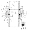
- the following drawing shows a pipe coupling according to the invention together with two pipes in axial section.
- a pipe coupling which serves to connect at least two pipes 1, 2.
- the pipe coupling has on each to be coupled pipe ends 3, 4 attached clutch rings 5, 6.
- at least one clutch rims 5, 6 cross-coupling shell 7 is realized.
- the coupling shell 7 is axially slidably connected to the one coupling ring 5 and engages over the other coupling ring 6.
- the coupling ring 5 is connected to the pipe end 3 of a pipe 1 blunt, while the other coupling ring 6 to the pipe end 4 of other tube 2 is also connected butt.
- circumferential welds 8 are provided in the context of the embodiment, because both the two tubes 1, 2 and the associated coupling rings 5, 6 each metallic, in particular made of steel, and each rotationally symmetrical compared to a pipe center line M are formed as rotational symmetry axis which is not mandatory.
- the two coupling rings 5, 6 are each connected in extension of the respective tubes 1, 2 to this, so that an associated pipe inner wall - Also in the field of pipe coupling - is designed predominantly heel-free and smooth.
- the coupling shell 7 is formed in the embodiment also rotationally symmetrical compared to the pipe center line M and in this case represents a sleeve ring.
- the coupling shell 7 and the sleeve ring is rotatably and axially slidably connected to the one coupling ring 5, via a screw 9. Actually could This site also a bayonet connection can be realized.
- the screw 9 is composed in detail of an internal thread 9a on the inside of the sleeve ring and the coupling shell 7 and an external thread 9b on the outside of the one coupling ring 5 together.
- the coupling shell or the sleeve ring 7 is equipped with a stop ring 10, which cooperates with an annular stop edge 11 on the other coupling ring 6 and engages over this.
- the two coupling rings 5, 6 are clamped together or released from each other.
- the distortion of the clutch rings 5, 6 without jamming and aligned and can be performed centered each other, the two coupling rings 5, 6 at their mutually facing end faces 12, 13 via intermeshing coupling surfaces 14, 15th
- the two coupling surfaces 14, 15 each form coupling rings 14, 15, which on the one hand are convex in cross-section and, on the other hand, concavely curved.
- the coupling surface 14 on the one coupling ring 5 has a convex curvature
- the coupling surface 15 is equipped on the other coupling ring 6 with a complementary concave curvature with approximately the same radius.
- an annular gap 16 between the other coupling ring 6 and the coupling shell 7 is formed, which ensures the centering and alignment of the other coupling ring 6 relative to the one coupling ring 5, without the other coupling ring 6 scraping, for example, on the inside of the coupling shell 7.
- the convex coupling surface 14 is curved inwardly towards the tube center line M, whereas the concave coupling surface 15 is equipped with a curvature facing outwardly.
- the other coupling ring 6 is accommodated in the coupling ring 5 connected to the coupling shell 7, as it were in a funnel, and can easily align and center through the interaction of the two coupling surfaces or coupling rings 14, 15 and due to the circumferential annular gap 16. This process also ensures that a ring seal 17, which is received in a circumferential annular groove 18, is not crushed or damaged.
- the two coupling rings 5, 6 enclose the said circumferential annular groove 18 for the annular seal 17.
- the circumferential annular groove 18 in the one, connected to the coupling shell 7, coupling ring 5 is formed and has a rectangular cross-sectional shape.
- the ring seal 17 is formed asymmetrically in cross-section and has a flat foot 17a and a rounded head 17b and a head end provided rounded contact surface.
- the rounded head 17b of the annular seal 17 bears against the end face 13 of the other coupling ring 6 and seals a gap 19 opening from the annular channel or the annular groove 18 for receiving the annular seal 17 towards the interior of the tube.
- this gap 19 ends at the annular seal 17, because further on the outside of the tube, the two adjoining coupling surfaces 14, 15 provide for a corresponding gap-free connection of the coupling rings 5, 6.
- the coupling shell 7 has a connected manipulation means 20th
- the manipulation means 20 are a plurality of webs connected to the coupling shell 7, which can, for example, be impacted in order to clamp the two coupling rings 5, 6 and consequently the tubes 1, 2 together or to one another to solve.
- the actuation methods are conceivable at this point and are encompassed by the invention.
- the ring seal 17 may also have a different shape than the one described, for example with a continuous circular cross section.
- the coupling shell 7 could also be connected to the associated coupling ring 5 in such a way that initially several recesses, for example four, are realized in the initial area similar to a bayonet connection and then several, for example two or three, complete threads of the screw connection 9 follow ,
Landscapes
- Engineering & Computer Science (AREA)
- General Engineering & Computer Science (AREA)
- Mechanical Engineering (AREA)
- Quick-Acting Or Multi-Walled Pipe Joints (AREA)
Priority Applications (2)
| Application Number | Priority Date | Filing Date | Title |
|---|---|---|---|
| EP06005015A EP1832794B1 (fr) | 2006-03-11 | 2006-03-11 | Raccord de tuyaux |
| DE200650003376 DE502006003376D1 (de) | 2006-03-11 | 2006-03-11 | Rohrkupplung |
Applications Claiming Priority (1)
| Application Number | Priority Date | Filing Date | Title |
|---|---|---|---|
| EP06005015A EP1832794B1 (fr) | 2006-03-11 | 2006-03-11 | Raccord de tuyaux |
Publications (2)
| Publication Number | Publication Date |
|---|---|
| EP1832794A1 true EP1832794A1 (fr) | 2007-09-12 |
| EP1832794B1 EP1832794B1 (fr) | 2009-04-08 |
Family
ID=36754560
Family Applications (1)
| Application Number | Title | Priority Date | Filing Date |
|---|---|---|---|
| EP06005015A Revoked EP1832794B1 (fr) | 2006-03-11 | 2006-03-11 | Raccord de tuyaux |
Country Status (2)
| Country | Link |
|---|---|
| EP (1) | EP1832794B1 (fr) |
| DE (1) | DE502006003376D1 (fr) |
Cited By (3)
| Publication number | Priority date | Publication date | Assignee | Title |
|---|---|---|---|---|
| DE102008015626A1 (de) | 2008-03-26 | 2009-10-01 | Dr. Ing. H.C. F. Porsche Aktiengesellschaft | Verbindung einer Saugluftleitung mit einem Luftfiltergehäuse |
| CN109027458A (zh) * | 2018-10-15 | 2018-12-18 | 浙江新世纪工程咨询有限公司温州分公司 | 市政排水管连接结构 |
| EP3578864A1 (fr) * | 2018-06-04 | 2019-12-11 | Siloanlagen Achberg Holding GmbH | Accouplement tubulaire pour installations de transport pour marchandises en vrac |
Citations (12)
| Publication number | Priority date | Publication date | Assignee | Title |
|---|---|---|---|---|
| DE122735C (fr) * | ||||
| US1071235A (en) * | 1912-03-23 | 1913-08-26 | Clyde S Hutton | Coupling. |
| GB387628A (en) * | 1932-09-29 | 1933-02-09 | Hermann Wingerath | Easily-detachable coupling for tubes |
| DE689468C (de) * | 1938-05-19 | 1940-03-21 | Bergedorfer Eisenwerk Akt Ges | Verschraubungen fuer Rohrleitungen |
| DE834928C (de) | 1950-09-21 | 1952-03-24 | Paul Kieselmann | Gummilose Verschraubung |
| DE1061142B (de) | 1955-09-20 | 1959-07-09 | Hans Zeller | Hartdichtung |
| US4802695A (en) * | 1986-05-12 | 1989-02-07 | Karl Weinhold | Pipe screwed connection |
| FR2630187A3 (fr) * | 1988-04-13 | 1989-10-20 | Conchon Michel | Raccord a souder perfectionne |
| DE4227319A1 (de) | 1992-08-18 | 1994-02-24 | Linnemann Friedrich | Rohrverschraubung |
| DE29511730U1 (de) | 1995-07-20 | 1995-09-28 | Karl Hamacher GmbH, 44866 Bochum | Steigrohrleitung für insbesondere den Brunnenbau |
| DE29704105U1 (de) | 1997-03-06 | 1997-05-22 | Karl Hamacher GmbH, 44866 Bochum | Rohrkupplung |
| DE20119672U1 (de) | 2001-12-05 | 2002-03-07 | Weinhold, Karl, Dipl.-Ing., 41464 Neuss | Rohrverbindungssystem zur Verbindung zweier baugleicher mit Rohrmuffen ausgestatteter Rohrkupplungsteile |
-
2006
- 2006-03-11 EP EP06005015A patent/EP1832794B1/fr not_active Revoked
- 2006-03-11 DE DE200650003376 patent/DE502006003376D1/de not_active Withdrawn - After Issue
Patent Citations (12)
| Publication number | Priority date | Publication date | Assignee | Title |
|---|---|---|---|---|
| DE122735C (fr) * | ||||
| US1071235A (en) * | 1912-03-23 | 1913-08-26 | Clyde S Hutton | Coupling. |
| GB387628A (en) * | 1932-09-29 | 1933-02-09 | Hermann Wingerath | Easily-detachable coupling for tubes |
| DE689468C (de) * | 1938-05-19 | 1940-03-21 | Bergedorfer Eisenwerk Akt Ges | Verschraubungen fuer Rohrleitungen |
| DE834928C (de) | 1950-09-21 | 1952-03-24 | Paul Kieselmann | Gummilose Verschraubung |
| DE1061142B (de) | 1955-09-20 | 1959-07-09 | Hans Zeller | Hartdichtung |
| US4802695A (en) * | 1986-05-12 | 1989-02-07 | Karl Weinhold | Pipe screwed connection |
| FR2630187A3 (fr) * | 1988-04-13 | 1989-10-20 | Conchon Michel | Raccord a souder perfectionne |
| DE4227319A1 (de) | 1992-08-18 | 1994-02-24 | Linnemann Friedrich | Rohrverschraubung |
| DE29511730U1 (de) | 1995-07-20 | 1995-09-28 | Karl Hamacher GmbH, 44866 Bochum | Steigrohrleitung für insbesondere den Brunnenbau |
| DE29704105U1 (de) | 1997-03-06 | 1997-05-22 | Karl Hamacher GmbH, 44866 Bochum | Rohrkupplung |
| DE20119672U1 (de) | 2001-12-05 | 2002-03-07 | Weinhold, Karl, Dipl.-Ing., 41464 Neuss | Rohrverbindungssystem zur Verbindung zweier baugleicher mit Rohrmuffen ausgestatteter Rohrkupplungsteile |
Cited By (3)
| Publication number | Priority date | Publication date | Assignee | Title |
|---|---|---|---|---|
| DE102008015626A1 (de) | 2008-03-26 | 2009-10-01 | Dr. Ing. H.C. F. Porsche Aktiengesellschaft | Verbindung einer Saugluftleitung mit einem Luftfiltergehäuse |
| EP3578864A1 (fr) * | 2018-06-04 | 2019-12-11 | Siloanlagen Achberg Holding GmbH | Accouplement tubulaire pour installations de transport pour marchandises en vrac |
| CN109027458A (zh) * | 2018-10-15 | 2018-12-18 | 浙江新世纪工程咨询有限公司温州分公司 | 市政排水管连接结构 |
Also Published As
| Publication number | Publication date |
|---|---|
| EP1832794B1 (fr) | 2009-04-08 |
| DE502006003376D1 (de) | 2009-05-20 |
Similar Documents
| Publication | Publication Date | Title |
|---|---|---|
| EP1998097B1 (fr) | Accouplement tubulaire, procédé d'accouplement tubulaire et de nettoyage automatique de moitiés d'accouplement lors de l'accouplement tubulaire | |
| EP2281134B1 (fr) | Dispositif de serrage pour fixer par serrage des tubulures de raccordement à des conduites | |
| EP3169853B1 (fr) | Tuyau flexible | |
| EP2542815B1 (fr) | Connecteur à emboîtement pour conduites de fluide | |
| WO2009150108A1 (fr) | Raccord par pression pour un tuyau, en particulier un tuyau en plastique ou un tuyau composite plastique-métal | |
| DE60204287T2 (de) | Kupplung zur verbindung eines rohrs oder schlauchs durch einschieben | |
| DE102010018954B4 (de) | Vorrichtung zum steckbaren Verbinden eines ersten Leitungsabschnitts mit einem zweiten Leitungsabschnitt einer Fluidleitung | |
| EP1832794B1 (fr) | Raccord de tuyaux | |
| EP2157352B1 (fr) | Raccord, en particulier raccord de tuyaux | |
| DE2623364A1 (de) | Rohr-verbindungsstueck | |
| WO2009030250A1 (fr) | Raccord pour tubes | |
| EP2137447B1 (fr) | Fiche de construction courte pour couplages hydrauliques | |
| DE10311801A1 (de) | Einrichtung zum Befestigen einer Leitung | |
| DE10007369A1 (de) | Rohrkupplung | |
| DE102014212379B4 (de) | Verbindungselement zur Verbindung eines Aggregates mit einer Druckleitung | |
| EP1865244B1 (fr) | Raccord, notamment raccord de tuyaux ou de conduites haute pression | |
| DE10320935B3 (de) | Anordnung zur Verbindung von zwei Rohrleitungen | |
| DE102009053388A1 (de) | Ventil mit Demotageschutz sowie Montagehilfe | |
| EP4600536A2 (fr) | Dispositif de connexion pour connecter une première extrémité de ligne à une deuxième extrémité de ligne | |
| DE3305526A1 (de) | Fernbetaetigbare klemmverbindungs-vorrichtung fuer zwei rohre oder zylinderische behaelter | |
| DE4318831C2 (de) | Kupplungsvorrichtung für Rohre | |
| DE102014018073B4 (de) | Kupplungsteil für eine Schraubkupplung für Druckmittelleitungen | |
| DE3608463A1 (de) | Steckkupplung | |
| DE9419253U1 (de) | Leitungskupplung für Fluidleitungen | |
| DE1908093C (de) | Schnell betatigbare Kupplung fur Rohre, Schlauche u dgl |
Legal Events
| Date | Code | Title | Description |
|---|---|---|---|
| PUAI | Public reference made under article 153(3) epc to a published international application that has entered the european phase |
Free format text: ORIGINAL CODE: 0009012 |
|
| AK | Designated contracting states |
Kind code of ref document: A1 Designated state(s): AT BE BG CH CY CZ DE DK EE ES FI FR GB GR HU IE IS IT LI LT LU LV MC NL PL PT RO SE SI SK TR |
|
| AX | Request for extension of the european patent |
Extension state: AL BA HR MK YU |
|
| 17P | Request for examination filed |
Effective date: 20070830 |
|
| AKX | Designation fees paid |
Designated state(s): CZ DE PL SI TR |
|
| 17Q | First examination report despatched |
Effective date: 20080708 |
|
| GRAP | Despatch of communication of intention to grant a patent |
Free format text: ORIGINAL CODE: EPIDOSNIGR1 |
|
| GRAS | Grant fee paid |
Free format text: ORIGINAL CODE: EPIDOSNIGR3 |
|
| GRAA | (expected) grant |
Free format text: ORIGINAL CODE: 0009210 |
|
| AK | Designated contracting states |
Kind code of ref document: B1 Designated state(s): CZ DE PL SI TR |
|
| REF | Corresponds to: |
Ref document number: 502006003376 Country of ref document: DE Date of ref document: 20090520 Kind code of ref document: P |
|
| PG25 | Lapsed in a contracting state [announced via postgrant information from national office to epo] |
Ref country code: SI Free format text: LAPSE BECAUSE OF FAILURE TO SUBMIT A TRANSLATION OF THE DESCRIPTION OR TO PAY THE FEE WITHIN THE PRESCRIBED TIME-LIMIT Effective date: 20090408 |
|
| PG25 | Lapsed in a contracting state [announced via postgrant information from national office to epo] |
Ref country code: PL Free format text: LAPSE BECAUSE OF FAILURE TO SUBMIT A TRANSLATION OF THE DESCRIPTION OR TO PAY THE FEE WITHIN THE PRESCRIBED TIME-LIMIT Effective date: 20090408 |
|
| PLBI | Opposition filed |
Free format text: ORIGINAL CODE: 0009260 |
|
| PG25 | Lapsed in a contracting state [announced via postgrant information from national office to epo] |
Ref country code: CZ Free format text: LAPSE BECAUSE OF FAILURE TO SUBMIT A TRANSLATION OF THE DESCRIPTION OR TO PAY THE FEE WITHIN THE PRESCRIBED TIME-LIMIT Effective date: 20090408 |
|
| 26 | Opposition filed |
Opponent name: WEINHOLD, KARL DIPL.-ING. (FH) Effective date: 20100105 |
|
| PLAX | Notice of opposition and request to file observation + time limit sent |
Free format text: ORIGINAL CODE: EPIDOSNOBS2 |
|
| PLAF | Information modified related to communication of a notice of opposition and request to file observations + time limit |
Free format text: ORIGINAL CODE: EPIDOSCOBS2 |
|
| PG25 | Lapsed in a contracting state [announced via postgrant information from national office to epo] |
Ref country code: DE Free format text: LAPSE BECAUSE OF THE APPLICANT RENOUNCES Effective date: 20101009 |
|
| RDAF | Communication despatched that patent is revoked |
Free format text: ORIGINAL CODE: EPIDOSNREV1 |
|
| REG | Reference to a national code |
Ref country code: DE Ref legal event code: R064 Ref document number: 502006003376 Country of ref document: DE Ref country code: DE Ref legal event code: R103 Ref document number: 502006003376 Country of ref document: DE |
|
| RDAG | Patent revoked |
Free format text: ORIGINAL CODE: 0009271 |
|
| STAA | Information on the status of an ep patent application or granted ep patent |
Free format text: STATUS: PATENT REVOKED |
|
| 27W | Patent revoked |
Effective date: 20110711 |
|
| PG25 | Lapsed in a contracting state [announced via postgrant information from national office to epo] |
Ref country code: DE Free format text: LAPSE BECAUSE OF THE APPLICANT RENOUNCES Effective date: 20101001 |