EP1832797A2 - Elément de raccordement avec section anti-rotation - Google Patents
Elément de raccordement avec section anti-rotation Download PDFInfo
- Publication number
- EP1832797A2 EP1832797A2 EP20070002487 EP07002487A EP1832797A2 EP 1832797 A2 EP1832797 A2 EP 1832797A2 EP 20070002487 EP20070002487 EP 20070002487 EP 07002487 A EP07002487 A EP 07002487A EP 1832797 A2 EP1832797 A2 EP 1832797A2
- Authority
- EP
- European Patent Office
- Prior art keywords
- connection element
- plug connection
- element according
- rotation portion
- collar
- Prior art date
- Legal status (The legal status is an assumption and is not a legal conclusion. Google has not performed a legal analysis and makes no representation as to the accuracy of the status listed.)
- Withdrawn
Links
- 239000004952 Polyamide Substances 0.000 claims description 3
- 230000002093 peripheral effect Effects 0.000 claims description 3
- 229920002647 polyamide Polymers 0.000 claims description 3
- 239000004033 plastic Substances 0.000 claims description 2
- 229920003023 plastic Polymers 0.000 claims description 2
- 229920001875 Ebonite Polymers 0.000 description 1
- 239000011324 bead Substances 0.000 description 1
- 239000004744 fabric Substances 0.000 description 1
- 229920002457 flexible plastic Polymers 0.000 description 1
- 238000002347 injection Methods 0.000 description 1
- 239000007924 injection Substances 0.000 description 1
- 239000000463 material Substances 0.000 description 1
- 230000002787 reinforcement Effects 0.000 description 1
Images

Classifications
-
- F—MECHANICAL ENGINEERING; LIGHTING; HEATING; WEAPONS; BLASTING
- F16—ENGINEERING ELEMENTS AND UNITS; GENERAL MEASURES FOR PRODUCING AND MAINTAINING EFFECTIVE FUNCTIONING OF MACHINES OR INSTALLATIONS; THERMAL INSULATION IN GENERAL
- F16L—PIPES; JOINTS OR FITTINGS FOR PIPES; SUPPORTS FOR PIPES, CABLES OR PROTECTIVE TUBING; MEANS FOR THERMAL INSULATION IN GENERAL
- F16L33/00—Arrangements for connecting hoses to rigid members; Rigid hose-connectors, i.e. single members engaging both hoses
- F16L33/24—Arrangements for connecting hoses to rigid members; Rigid hose-connectors, i.e. single members engaging both hoses with parts screwed directly on or into the hose
Definitions
- the invention relates to a plug-in connection element for connecting a hydraulic line, with a tubular base body, which has an anti-rotation portion.
- German Offenlegungsschrift DE 33 45 203 A1 discloses a flexible pressure hose having an end to which a connection fitting is pressure-tight and positively secured.
- a connection fitting is pressure-tight and positively secured.
- beads are formed on the surface at the periphery of the connection fitting, which form elevations on the inner side of the connection fitting, which press into the surface of the pressure hose with positive locking.
- the object of the invention is to provide a connector element according to the preamble of claim 1, which allows in a simple manner a stable rotationally fixed connection between the connector element and a hydraulic line.
- a plug-in connection element for connecting a hydraulic line, with a tubular base body, which has a Vermos Anlagensabrough, characterized in that the anti-rotation portion has a profile, in particular a corrugation, which or on the surface has an axial and a peripheral portion.
- the hydraulic line which is preferably a hard rubber tube with a fabric reinforcement, with a rotational movement on the connector element can be applied.
- the profile cuts into the hydraulic line.
- the hydraulic line in particular in the opposite direction of the thread extension, secured against rotation.
- a preferred embodiment of the connector element is characterized in that the profile forms a self-locking thread.
- the thread profile and the thread pitch are chosen so that an independent release of the hydraulic line is prevented by the connector element.
- a further preferred embodiment of the plug connection element is characterized in that the thread is designed as a single-pointed thread. By a small pitch angle and a large flank angle a large frictional force is achieved.
- the object is in a connector element for connecting a hydraulic line, with a tubular body having a Vermosommesabites, alternatively or additionally also solved in that between the anti-rotation portion and a free end of the tubular body, a collar is provided.
- the anti-rotation portion is provided with anti-rotation elements, which cut into these when connecting with a hydraulic line, with chips are free.
- the collar prevents the chips from getting into the interior of the hydraulic line.
- Another preferred embodiment of the connector element is characterized in that the collar tapers towards the free end of the tubular base body. This simplifies establishing the connection with the hydraulic line.
- a further preferred embodiment of the plug connection element is characterized in that the collar has the shape of a truncated cone on the outside. This shape has proven to be particularly advantageous in the context of the present invention.
- a further preferred embodiment of the connector element is characterized in that the tubular base body between the collar and the anti-rotation portion outside the shape of a straight circular cylinder. This ensures a good seal between the connector element and the hydraulic line.
- a further preferred embodiment of the plug-in connection element is characterized in that the rotation-preventing section has an axial section tapering towards the collar. This simplifies establishing the connection with the hydraulic line.
- Another preferred embodiment of the connector element is characterized in that the anti-rotation portion a corrugation with raised corrugations has, which run parallel to each other. The outwardly raised corrugations dig in establishing the connection in the hydraulic line.
- Another preferred embodiment of the connector element is characterized in that the corrugations extend in the axial direction. Thereby, a rotation of the connector element relative to the hydraulic line, and vice versa, reliably prevented.
- Another preferred embodiment of the connector element is characterized in that the corrugations run obliquely. As a result, the corrugation when making the connection with the hydraulic line acts like a thread.
- Another preferred embodiment of the connector element is characterized in that the corrugations have an outwardly tapered Riffelquerites. This ensures that the corrugation is cut into the hydraulic line.
- a further preferred embodiment of the connector element is characterized in that the tubular base body with the anti-rotation portion and the collar is integrally formed of plastic, in particular polyamide.
- the plug connection element is preferably formed as an injection molded part of polyamide PA 12 or PA 66.
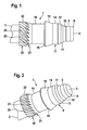
- the plug-in connection element 1 has a cut-off end 2 shown in FIGS. 1 and 2 and a free end 3, onto which one end of a hydraulic line (not shown) can be plugged.
- the hydraulic line is preferably a pressure-resistant, flexible plastic hose.
- the connector element 1 comprises a tubular base body 5, which is provided at the free end 3 with a rounding 8.
- the rounding 8 is followed by a circular-cylindrical jacket-shaped section 9, a widening section 10, a truncated cone-like section 11 and a further widening section 12.
- the diameters of the sections 10 to 12 increase away from the free end 3.
- the widening section 12 is followed by a circular cylinder jacket-shaped section 14.
- the circular cylinder jacket-shaped portion 14 is bounded by a collar 15 which has the shape of a truncated cone, which tapers towards the free end 3.
- the collar 15 On the side facing away from the free end 3, the collar 15 is bounded by a shoulder 16.
- the shoulder 16 merges into a circular cylinder jacket-shaped section 18.
- On the circular cylinder jacket-shaped portion 18 is followed by an anti-rotation portion 20.
- the anti-rotation portion 20 includes in the axial direction extending from the free end 3 away portion 21, which merges into a circular cylindrical jacket-shaped portion 22.
- the anti-rotation portion 20 is provided with a corrugation which extends over the sections 21 and 22 and is also referred to as a profile.
- the corrugation comprises a plurality of corrugations 24, 25, which run obliquely.
- the corrugations are distributed uniformly over the circumference of the rotation-preventing section 20.
- a plug connection element 31 is shown in different views.
- the plug connection element 31 is similar to the plug connection element 1 shown in FIGS. 1 and 2.
- the plug connection element 31 has an end 32 and a free end 33 for connecting a hydraulic line hose (not shown).
- a tubular body 35 extends with different sections.
- the main body 35 has up to a collar 36, the same sections as the base body 5 shown in Figures 1 and 2.
- a circular cylinder jacket-shaped portion 38 and an anti-rotation portion 37 follow.
- the anti-rotation portion 37 has a corrugation with a plurality of corrugations 39 and 40 on.
- the corrugations 39, 40 are not inclined as in the previous embodiment, but in the axial direction parallel to each other.
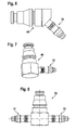
- FIG. 7 shows another angle connector 48, which is likewise equipped with a plug connection element 31, as shown in different views in FIGS. 3 to 5.
- the angle connector 48 has two mutually perpendicularly arranged plug connection elements.
- a T-connector 54 is shown having a male connector 31, as shown in Figures 3 to 5 in different views, and another connector element 61.
- the two connector elements 31 and 61 extend on an axis in opposite directions and are otherwise identical.
Landscapes
- Engineering & Computer Science (AREA)
- General Engineering & Computer Science (AREA)
- Mechanical Engineering (AREA)
- Quick-Acting Or Multi-Walled Pipe Joints (AREA)
Applications Claiming Priority (1)
| Application Number | Priority Date | Filing Date | Title |
|---|---|---|---|
| DE102006010142 | 2006-03-06 |
Publications (1)
| Publication Number | Publication Date |
|---|---|
| EP1832797A2 true EP1832797A2 (fr) | 2007-09-12 |
Family
ID=38066630
Family Applications (1)
| Application Number | Title | Priority Date | Filing Date |
|---|---|---|---|
| EP20070002487 Withdrawn EP1832797A2 (fr) | 2006-03-06 | 2007-02-06 | Elément de raccordement avec section anti-rotation |
Country Status (1)
| Country | Link |
|---|---|
| EP (1) | EP1832797A2 (fr) |
Cited By (1)
| Publication number | Priority date | Publication date | Assignee | Title |
|---|---|---|---|---|
| JP2013221535A (ja) * | 2012-04-13 | 2013-10-28 | Nifco Inc | ホースコネクタ |
-
2007
- 2007-02-06 EP EP20070002487 patent/EP1832797A2/fr not_active Withdrawn
Cited By (1)
| Publication number | Priority date | Publication date | Assignee | Title |
|---|---|---|---|---|
| JP2013221535A (ja) * | 2012-04-13 | 2013-10-28 | Nifco Inc | ホースコネクタ |
Similar Documents
| Publication | Publication Date | Title |
|---|---|---|
| DE10215607B4 (de) | Rohrverbinder | |
| DE112008003080B4 (de) | Schlauchleitungsverbinder sowie Leitungssatz | |
| EP0728979A1 (fr) | Raccord étanche entre un tuyau en matière plastique et une pièce de raccordement fabriquée en métal | |
| EP2090212B1 (fr) | Dispositif de prise sur un tuyau d'aspirateur | |
| DE4412615A1 (de) | Schiebehülsen-Verbindung für Kunststoffrohre | |
| EP3527866B1 (fr) | Raccord pour tuyau souple | |
| EP2025988B1 (fr) | Raccord pour un tuyau, en particulier un tuyau en plastique ou un tuyau composite en plastique et métal | |
| DE19956084A1 (de) | Dichtungseinheit | |
| DE2822259C2 (de) | Schnellkupplung für rohrförmige Leitungen, insbesondere für Flüssigkeiten | |
| DE19542463B4 (de) | Rohrkupplung | |
| EP0405245A2 (fr) | Raccord de tuyau flexible pour un tuyau flexible à haute pression | |
| EP2975311B1 (fr) | Raccord a vis pour tuyaux souples | |
| EP1832797A2 (fr) | Elément de raccordement avec section anti-rotation | |
| DE2630814B2 (de) | Rohrverbindung für unvorbereitete Enden mit einer Dichtungshulse | |
| DE102007005775A1 (de) | Steckverbindungselement | |
| DE102010021411A1 (de) | Steckverbindungsanordnung und Befestigungseinrichtung | |
| DE19653866B4 (de) | Schnellkupplung zum Anschließen einer Schlauchleitung | |
| DE202021106545U1 (de) | Tülle mit Gelenkverbindung | |
| DE2045870B1 (de) | Anschlussverschraubung f]r rohre u. dgl., insbesondere aus kunststoff | |
| EP4332420B1 (fr) | Conduite de fluide dotée d'un tube ondulé acheminant le fluide | |
| EP1098125B1 (fr) | Procédé pour la réalisation d'un accouplement de serrage et connecteur à serrage à deux pièces | |
| EP0288993A1 (fr) | Dispositif pour assemblage des extrémités coaxiales de deux tuyaux sans manchons | |
| EP1398556B1 (fr) | Raccord | |
| DE4439870C2 (de) | Druckmittelleitender Anschluß- und Verbindungskörper mit mindestens einem patrizenförmigen Schlauchstutzen | |
| DE19911812C2 (de) | Schlauchanschlußvorrichtung |
Legal Events
| Date | Code | Title | Description |
|---|---|---|---|
| PUAI | Public reference made under article 153(3) epc to a published international application that has entered the european phase |
Free format text: ORIGINAL CODE: 0009012 |
|
| AK | Designated contracting states |
Kind code of ref document: A2 Designated state(s): AT BE BG CH CY CZ DE DK EE ES FI FR GB GR HU IE IS IT LI LT LU LV MC NL PL PT RO SE SI SK TR |
|
| AX | Request for extension of the european patent |
Extension state: AL BA HR MK YU |
|
| STAA | Information on the status of an ep patent application or granted ep patent |
Free format text: STATUS: THE APPLICATION IS DEEMED TO BE WITHDRAWN |
|
| 18D | Application deemed to be withdrawn |
Effective date: 20090901 |
|
| P01 | Opt-out of the competence of the unified patent court (upc) registered |
Effective date: 20230523 |