EP1832818B1 - Installation d'aération - Google Patents
Installation d'aération Download PDFInfo
- Publication number
- EP1832818B1 EP1832818B1 EP07004473.0A EP07004473A EP1832818B1 EP 1832818 B1 EP1832818 B1 EP 1832818B1 EP 07004473 A EP07004473 A EP 07004473A EP 1832818 B1 EP1832818 B1 EP 1832818B1
- Authority
- EP
- European Patent Office
- Prior art keywords
- ventilation
- air
- shows
- unit
- heat exchanger
- Prior art date
- Legal status (The legal status is an assumption and is not a legal conclusion. Google has not performed a legal analysis and makes no representation as to the accuracy of the status listed.)
- Active
Links
Images







Classifications
-
- F—MECHANICAL ENGINEERING; LIGHTING; HEATING; WEAPONS; BLASTING
- F24—HEATING; RANGES; VENTILATING
- F24F—AIR-CONDITIONING; AIR-HUMIDIFICATION; VENTILATION; USE OF AIR CURRENTS FOR SCREENING
- F24F12/00—Use of energy recovery systems in air conditioning, ventilation or screening
- F24F12/001—Use of energy recovery systems in air conditioning, ventilation or screening with heat-exchange between supplied and exhausted air
- F24F12/006—Use of energy recovery systems in air conditioning, ventilation or screening with heat-exchange between supplied and exhausted air using an air-to-air heat exchanger
-
- F—MECHANICAL ENGINEERING; LIGHTING; HEATING; WEAPONS; BLASTING
- F24—HEATING; RANGES; VENTILATING
- F24F—AIR-CONDITIONING; AIR-HUMIDIFICATION; VENTILATION; USE OF AIR CURRENTS FOR SCREENING
- F24F2221/00—Details or features not otherwise provided for
- F24F2221/36—Modules, e.g. for an easy mounting or transport
-
- Y—GENERAL TAGGING OF NEW TECHNOLOGICAL DEVELOPMENTS; GENERAL TAGGING OF CROSS-SECTIONAL TECHNOLOGIES SPANNING OVER SEVERAL SECTIONS OF THE IPC; TECHNICAL SUBJECTS COVERED BY FORMER USPC CROSS-REFERENCE ART COLLECTIONS [XRACs] AND DIGESTS
- Y02—TECHNOLOGIES OR APPLICATIONS FOR MITIGATION OR ADAPTATION AGAINST CLIMATE CHANGE
- Y02B—CLIMATE CHANGE MITIGATION TECHNOLOGIES RELATED TO BUILDINGS, e.g. HOUSING, HOUSE APPLIANCES OR RELATED END-USER APPLICATIONS
- Y02B30/00—Energy efficient heating, ventilation or air conditioning [HVAC]
- Y02B30/56—Heat recovery units
Definitions
- the present application relates to a ventilation system.
- Such ventilation systems typically have a housing with a heat exchanger, via which air is conveyed by means of a blower.
- the housing typically has connections for supply, exhaust, exhaust and / or fresh air.
- a ventilation system with an internally arranged cross-counterflow heat exchanger is described as an application example, in which an energy exchange takes place between waste air and fresh air.
- a ventilation device for a building room is known, it being a so-called single room device for decentralized ventilation with heat recovery.
- a molded body made of sound-absorbing, heat-insulating material is arranged in a housing, in which air ducts which are open towards the front are provided, with air-guiding openings at the back are provided to establish a connection with the fresh air.
- a ventilation device for ventilation of rooms according to DE 32 08 392 A1 is made of vibration and sound absorbing and partially flexible materials.
- the front and back sides have covered panels with openings.
- a ventilation unit with a double-shell housing is from the DE 85 07 233 known. It contains the operational installation devices, such as a replaceable air filter, an electric heating element and the blower. A rear part of the interior is divided by a partition as an air outlet space with at least one outlet nozzle.
- a ventilation system which is arranged under a window or in front of an outer facade and is received flush with the floor in a floor or floor recess, is from the DE 101 22 488 known. Mixed operation for partially recirculated room air and incoming air via a heat exchanger is possible with an air guide flap.
- a room ventilation unit which is composed in modular construction, a single room should be ventilated. It should be easy to install.
- a basic unit serves as an independent, fully functional room ventilation system in which a control module, a condensate drain and a condensate treatment system are arranged.
- a self-centering additional ventilation module can be stacked in height by its own weight on the base unit.
- a room ventilation unit in modular design for a single room with a central connection for fresh air and exhaust air is off DE 102 55 172 A1 known.
- additional ventilation modules can self-center and, due to their own weight, can be stacked in height on the basic unit by means of sealants introduced.
- a central home ventilation system for controlled home ventilation in a low-energy house is made of Zahn, D .: Who sits in the greenhouse ... In: sbz. ISSN 1616-2285. 1990, Issue 5/1991, page 171.
- a connection is provided on the device for exhaust gases from a fossil combustion.
- a ventilation device with a device housing is known.
- a first inlet connection for sucking in air from the interior of a room and a first outlet connection for ejecting air into the interior of the room are provided.
- a second inlet connector for sucking in air from outside the room and a second outlet connector for ejecting air to the outside are formed.
- a zone formation member is provided by which the inside of the device case is divided into an air supply passage and an air discharge passage.
- a blower device is provided for the air supply and one or more heat exchanger elements are installed.
- Guide rails are provided for positioning and fastening a first zone formation element and further components and for guiding the heat exchanger element to a fixed position in the housing.
- a ventilation system which has a housing, a slide-in unit and a first and second air distribution duct.
- the air distribution channel is preferably arranged on a first side of the housing.
- the ventilation system also has at least one first connection, which is arranged on a second side of the housing. This first connection is used to supply fresh air and exhaust air.
- the ventilation devices or ventilation systems described here are typically mounted on a wall, a ceiling or on the floor, for example by means of threaded bolts in a building.
- the housing of the ventilation device can be made, for example, from sheet metal, plastic plates or from a frame, which can be equipped with a sound and heat insulating material on the inside or outside.
- Fig. 1 shows a perspective view of a ventilation device according to a first embodiment.
- the device has an outer wall duct 102 (preferably with an outer wall attachment 101) for fresh and / or exhaust air.
- the other components of the ventilation device are arranged in a frame 103.
- On the long side of the device there are some connection options 104 for supply air or extract air ducts. Further connection options 105 for supply air and extract air ducts are provided on one end of the device.
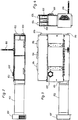
- Fig. 2 shows a side view of the ventilation unit of Fig. 1
- a connection 107 for exhaust air and a line 106 for condensate is provided. These two elements are preferably arranged on the underside of the device. When line 106 is connected upwards, the condensate is conveyed by a pump.
- the connection 107 preferably serves as a direct connection for exhaust air in a bathroom.
- Fig. 3 shows a view of the underside of the ventilation unit of Fig. 1 ,
- the ventilation unit has a connection for exhaust air 107 on its underside.
- the ventilation device has a connection 115 on each of its two end faces, to which the outer wall duct 102 can be connected. If the outer wall bushing 102 is connected on the left end side, the connection 115 can be closed accordingly or remains closed.
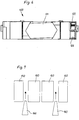
- Fig. 4 shows a view of the front of the ventilation unit.
- the ventilation device has connection positions 104, 105 for supply air ducts and a connection for exhaust air 107.
- Fig. 5 shows a perspective view of a frame of the ventilation device of FIG Fig. 1 .
- the frame 103 is constructed from a large number of struts and can accommodate the further elements of the ventilation device.
- Fig. 6 shows a side view of a drawer 400 for the ventilation device of FIG Fig. 1 ,
- the insert 400 has a receptacle 121 for a heat exchanger and at least one ventilation duct 122.
- the receptacle 121 is slightly chamfered so that the condensate of the heat exchanger can run off.
- the ventilation device preferably has a maintenance flap on its lower side.
- the individual components are secured against falling out by interlocks.
- the sheet metal frame 103 has some sheet metal strips which protrude into the maintenance opening. By pushing the corresponding elements of the heating device into the device and moving it horizontally in the device, all parts can be secured against falling out.
- Fig. 7 shows a schematic representation of the interaction of different elements of a ventilation device.
- the heat exchanger has a flat seal to the adjacent parts on its entire frame footprint.
- filter drawers 160 configured in a wedge shape are inserted between the various elements 160 from below.
- the filter drawers 160 are pulled down out of the device, for example, for a filter change.
- a force is exerted on the respective elements of the device and of the heat exchanger due to their wedge-shaped design in order to obtain the above-described seal or the flat seal.
- connection positions 104, 105 Due to the design of the different connection positions 104, 105, external air ducts can be variably connected to the ventilation device. This means that fresh and exhaust air connections can be connected to two different sides of the device.
- Fig. 8 shows a schematic representation of the operation of a ventilation device according to a second embodiment.
- the ventilation device has a connection 215 for an outer wall duct and a plurality of connections 204, 205 for exhaust air and supply air, the connections for exhaust air and supply air 204, 205 being arranged on the side opposite the connection 205.
- Fresh air FRL is passed through port 215 through a filter 260 through cross-counterflow heat exchanger 201.
- the air heated by the heat exchanger 201 is blown as a supply air ZL, preferably via a supply air fan 210 through a connection 204.
- the exhaust air AL from one or more rooms can enter the ventilation unit through the corresponding connections 204, 205.
- the connections 204, 205 for the exhaust air AL are connected to one another, and the entire exhaust air is then fed through a filter 260 to the heat exchanger 201, where the heat of the exhaust air is transferred to the incoming fresh air.
- the Cooled exhaust air is then preferably discharged to the outside via an exhaust air fan 210 via the connection 215 as exhaust air FL, for example via an outer wall duct.
- the filters 260 can be designed as filter drawers configured in a wedge shape.
- the heat exchanger 201 is preferably slightly inclined to the condensate drain 206, in order thus to allow the condensate to drain through the condensate drain 206.
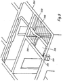
- Fig. 9 shows a perspective view of a ventilation device installed in a building.
- the ventilation unit 200 is mounted in a corner of a room on the ceiling or near the ceiling.
- the device is connected to an outer wall attachment 201 on the outer wall via an outer wall duct 202.
- On the other side of the device several ventilation ducts 220, 230 are arranged, which lead to different rooms in the building.
- the ventilation unit 200 is preferably connected to every room in the apartment or in the building.
- an intermediate ceiling 240 can be provided.
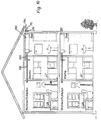
- Fig. 10 shows a sectional view of a building with a ventilation device according to one of the embodiments of the invention.
- the ventilation device 200 is preferably mounted on the ceiling in a bathroom.
- the ventilation ducts 230, 220 connect every room in the apartment to the ventilation device 200.
- the device is coupled to the outside via an outer wall duct 215, so that fresh air FLR can be supplied and exhaust air FL can be removed.
- ventilation slots or ventilation openings 280 can be provided in the floor or in the lower region of the intermediate walls.
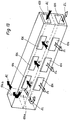
- Fig. 11 shows a perspective view of a ventilation device according to a third embodiment.
- the ventilation device has a housing 103, which has a slide-in unit 400, which is designed to receive the heat exchanger.
- Two ventilation ducts are shown on the left and right of the plug-in unit on the long side of the ventilation unit.
- Openings 104 are arranged in the ventilation ducts. The respective openings 104 are selected in accordance with the installation conditions. The other openings are then closed accordingly or remain closed. While the upper openings 104 are used for the exhaust air AL, the lower openings are used for the supply air ZL. Alternatively, this can be reversed.
- Openings 105 are also provided on the front of the device, which can be used both for the exhaust air AL and for the supply air ZL. Two openings are also arranged on the inside of the channels, preferably at the ends of the channels. The appropriate air is supplied to or removed from the heat exchanger by means of these openings and the ventilation ducts.
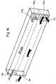
- Fig. 12 shows a schematic view of a plug-in unit 400 with the heat exchanger 201.
- the upper opening 115d interacts with openings on the inside of the channels and serves to suck in fresh air FRL, which is passed through the heat exchanger 201 and exits the device as supply air ZL.
- the exhaust air AL is drawn in through an opening 104d, passed through the heat exchanger and discharged as exhaust air from the device.
- Fig. 13 shows a schematic representation of the air distribution channels according to a third embodiment.
- the air distribution channels have a multiplicity of openings 104 on their long side and at least two openings 105 each on their front side.
- the supply air is sucked in through the opening 104a on the inside and exits again through the openings 104 and / or 105.
- the exhaust air AL is sucked in through the upper opening 104 and / or 105 and is discharged through the opening 104b on the inside.
- Fig. 14 shows a schematic representation of the ventilation ducts according to the third embodiment. Exhaust air FL is sucked in through the lower opening 115a and released again through the lower opening 115. The fresh air FRL is sucked in through the upper opening 115 and discharged again through the upper opening 115b on the inside.
- Fig. 15 shows a schematic representation of the ventilation ducts according to the third embodiment.
- the fresh air FRL is sucked in through the upper opening 115 and immediately output through the upper opening 115b on the inside.
- the exhaust air FL is sucked in through the lower inner opening 115a and discharged again through the lower opening 115.
- Fig. 16 shows a schematic representation of the plug-in unit 400.
- the plug-in unit according to the third exemplary embodiment has a supply air fan 210 and an exhaust air fan 210.
- the cross-countercurrent heat exchanger 201 is arranged in the insert unit at a slightly inclined position.
- wedge-shaped filter inserts 260 which can be pulled out in the direction of the arrow for maintenance or cleaning.
- Fig. 17 shows a schematic representation of the ventilation device 200 according to the third embodiment.
- the ventilation device 200 has a flap 300 which can be opened downward, so that the individual elements of the insert unit, for example the filter elements, can be removed, for example so that they can be cleaned or serviced.
- the ventilation device 200 according to the invention or the ventilation system according to the invention has a slide-in unit 400 which can accommodate, for example, the heat exchanger 201 and the filter units 260. Furthermore, the plug-in unit can have the corresponding supply air or exhaust air fans 210. To the left and right of the plug-in unit, ie preferably on the long side of the housing, two ventilation channels or air distribution channels are arranged. These air distribution ducts each have a connection option 105 and / or connection option 115 on their two end faces and a plurality of connection options 104 on the outside on their long side. To ensure a connection with the plug-in unit, the Air distribution channels each have an opening on the inside at both ends.
- openings can be closed according to the installation or assembly situation, so that there is a high degree of variation with regard to the connections.
- the openings are broken out or cracked as required, the openings which are not required remaining closed.
- the breaking out is advantageously carried out by embossing, perforations or the like. allows.
- embossing, perforations or the like allows.
- styrofoam it is particularly easy to provide predetermined breaking points which are produced by reducing the material thickness. Nevertheless, the wall remains completely closed when openings are not required, which is an advantage over perforation.
- connection options described above on the inside of the ventilation ducts correspond to corresponding openings in the plug-in unit, so that the corresponding air circulation is ensured.
- FIG. 13 Both the connections in the ventilation ducts to the outside (104, 105) and to the inside (104a, 104b) are shown.
- the inner connection options 104a, 104b serve to connect the ventilation ducts to the corresponding openings in the plug-in unit.
Landscapes
- Engineering & Computer Science (AREA)
- Chemical & Material Sciences (AREA)
- Combustion & Propulsion (AREA)
- Mechanical Engineering (AREA)
- General Engineering & Computer Science (AREA)
- Ventilation (AREA)
- Building Environments (AREA)
- Central Air Conditioning (AREA)
Claims (6)
- Installation de ventilation, comportant
un boîtier (103),
une unité de cartouche (400) qui présente un échangeur de chaleur (201),
un premier et un deuxième canal de répartition d'air avec au moins deux possibilités de raccordement pour des canaux d'air entrant et/ou au moins deux possibilités de raccordement pour des canaux d'air sortant, qui sont disposés sur un premier côté du boîtier (103), et
au moins un premier raccord (115, 215), disposé sur un deuxième côté du boîtier (103), destiné à faire entrer l'air frais (FRL) et à faire sortir l'air évacué (FL). - Installation de ventilation selon la revendication 1, comportant au moins un deuxième raccord le long du deuxième canal de répartition d'air et/ou sur le deuxième côté du boîtier.
- Installation de ventilation selon la revendication 1, comportant au moins un deuxième raccord le long du premier et du deuxième canal de répartition d'air et/ou sur le deuxième côté du boîtier.
- Installation de ventilation selon l'une des revendications 1, 2 et 3, dans laquelle un troisième raccord (107) pour l'air sortant (AL) est disponible sur la face inférieure.
- Installation de ventilation selon l'une des revendications précédentes, comportant
au moins une unité de filtre en forme de coin (160, 260). - Installation de ventilation selon l'une des revendications précédentes, dans laquelle les canaux de répartition d'air présentent une pluralité de possibilités de raccordement sur leur paroi extérieure ainsi qu'au moins deux possibilités de raccordement sur leur paroi intérieure.
Applications Claiming Priority (1)
| Application Number | Priority Date | Filing Date | Title |
|---|---|---|---|
| DE102006010553A DE102006010553A1 (de) | 2006-03-06 | 2006-03-06 | Lüftungsanlage |
Publications (3)
| Publication Number | Publication Date |
|---|---|
| EP1832818A2 EP1832818A2 (fr) | 2007-09-12 |
| EP1832818A3 EP1832818A3 (fr) | 2009-08-19 |
| EP1832818B1 true EP1832818B1 (fr) | 2019-12-25 |
Family
ID=38117015
Family Applications (1)
| Application Number | Title | Priority Date | Filing Date |
|---|---|---|---|
| EP07004473.0A Active EP1832818B1 (fr) | 2006-03-06 | 2007-03-05 | Installation d'aération |
Country Status (2)
| Country | Link |
|---|---|
| EP (1) | EP1832818B1 (fr) |
| DE (1) | DE102006010553A1 (fr) |
Families Citing this family (9)
| Publication number | Priority date | Publication date | Assignee | Title |
|---|---|---|---|---|
| FR2944588B1 (fr) * | 2009-04-15 | 2013-05-10 | Alain Bailloeuil | Plenum modulaire de soufflerie. |
| GB2499582B (en) * | 2012-02-17 | 2018-11-21 | Flakt Woods Ltd | Modular air movement apparatus |
| DE202012003192U1 (de) * | 2012-03-29 | 2013-07-01 | Stiebel Eltron Gmbh & Co. Kg | Lüftungsanlage |
| FI20140087A7 (fi) * | 2014-03-26 | 2015-09-27 | Janovent Oy | Huonetilakohtainen ilmanvaihtopalkki sekä ilmanvaihtopalkkijono |
| FR3039635B1 (fr) * | 2015-07-30 | 2019-12-27 | Inex Bet | Systeme de renouvellement et de traitement d'air decentralise, et dispositif de renouvellement et de traitement d'air pour un tel systeme |
| CN107975902A (zh) * | 2017-11-17 | 2018-05-01 | 重庆茗昇医疗科技有限公司 | 一种医疗生产用通风换气设备 |
| DE102018122489A1 (de) | 2018-09-14 | 2020-03-19 | Akg Verwaltungsgesellschaft Mbh | Schwadenkondensator für ein Gargerät sowie Gargerät mit einem solchen Schwadenkondensator |
| DE102019125523B3 (de) * | 2019-09-23 | 2020-08-13 | Viessmann Werke Gmbh & Co Kg | Mehrraumgebäude-Lüftungsanlage und Verfahren zu deren Betrieb |
| CN116221825B (zh) * | 2023-03-03 | 2025-09-12 | 宁波奥克斯电气有限公司 | 新风装置及具有其的空调器 |
Family Cites Families (8)
| Publication number | Priority date | Publication date | Assignee | Title |
|---|---|---|---|---|
| NL8102321A (nl) * | 1981-05-12 | 1982-12-01 | Johannes Boertien | Warmtewisselaar. |
| DE19907844C2 (de) * | 1999-02-24 | 2002-09-12 | Fenstersystemlueftung Gmbh & C | Lüftungsgerät für die Räume von Gebäuden |
| GB0006179D0 (en) * | 2000-03-16 | 2000-05-03 | Smiths Industries Plc | Units |
| CN1226570C (zh) * | 2001-03-30 | 2005-11-09 | 大金工业株式会社 | 换气装置及换气装置的组装方法 |
| DE10255172A1 (de) * | 2002-11-27 | 2004-06-17 | Flib Industriebeteiligung Gmbh | Raumlüftungsgerät |
| AU2003271207A1 (en) * | 2003-10-14 | 2005-04-27 | Lg Electronics, Inc. | Ventilator |
| KR100556431B1 (ko) * | 2004-06-24 | 2006-03-03 | 엘지전자 주식회사 | 공기청정 겸용 환기시스템 |
| CH696891A5 (de) * | 2004-08-02 | 2008-01-15 | Atum Gmbh | Einrichtung zur Raumlüftung und Einbaumodul zur Raumlüftung |
-
2006
- 2006-03-06 DE DE102006010553A patent/DE102006010553A1/de not_active Withdrawn
-
2007
- 2007-03-05 EP EP07004473.0A patent/EP1832818B1/fr active Active
Non-Patent Citations (1)
| Title |
|---|
| None * |
Also Published As
| Publication number | Publication date |
|---|---|
| EP1832818A3 (fr) | 2009-08-19 |
| EP1832818A2 (fr) | 2007-09-12 |
| DE102006010553A1 (de) | 2007-09-13 |
Similar Documents
| Publication | Publication Date | Title |
|---|---|---|
| EP1832818B1 (fr) | Installation d'aération | |
| EP2594725B1 (fr) | Fenêtre | |
| DE19534843C2 (de) | Rolladenaggregat | |
| DE102008053958A1 (de) | Kühlanordnung für einen Schaltschrank | |
| DE4343107C1 (de) | Lüftungssystem | |
| WO2023089138A1 (fr) | Système de climatisation d'espaces intérieurs d'un bâtiment | |
| EP2450520A2 (fr) | Système d'aération contrôlé pour un bâtiment par un élément de porte associé | |
| EP2846108A1 (fr) | Sortie d'air au plafond | |
| EP0112572B1 (fr) | Cadre pour portes ou fenêtres et caisse, plus spécialement caisse de volet, placée au dessus du cadre | |
| DE102007027839A1 (de) | Modulares Lüftungssystem | |
| CH696891A5 (de) | Einrichtung zur Raumlüftung und Einbaumodul zur Raumlüftung | |
| DE102005011222A1 (de) | Lüftungsanlage | |
| DE10255172A1 (de) | Raumlüftungsgerät | |
| EP2161512B1 (fr) | Appareil d'aération décentralisé et installation d'aération dotée d'un tel appareil | |
| DE102009017053A1 (de) | Wärmetauschervorrichtung | |
| DE202011051827U1 (de) | Lüftungssystem, insbesondere kontrolliertes Lüftungssystem für ein Gebäude sowie ein Türelement hierfür | |
| DE3248227A1 (de) | Umlaufende einfassung fuer tueren oder fenster, sowie kastenbauteil, insbesondere rolladenkasten, zur verwendung oberhalb der einfassung | |
| AT500559B1 (de) | Raumlufttechnische einrichtung | |
| EP0855560B1 (fr) | Dispositif de ventilation | |
| EP0828118A2 (fr) | Dispositif de ventilation pour aérer et désaérer simultanément des locaux | |
| EP2597382B1 (fr) | Appareil d'aération | |
| DE10210873B4 (de) | Rolladenkasten zur Verwendung an einer Gebäudetür oder an einem Gebäudefenster mit einer Lüftungsvorrichtung | |
| EP3086050B1 (fr) | Dispositif d'aeration decentralise encastrable | |
| DE10139927A1 (de) | Gebäude mit einer Be- und Entlüftungsanlage und Verfahren zur Sanierung derartiger Wohngebäude | |
| DE29608561U1 (de) | Vorrichtung zur Lüftung von Gebäuderäumen |
Legal Events
| Date | Code | Title | Description |
|---|---|---|---|
| PUAI | Public reference made under article 153(3) epc to a published international application that has entered the european phase |
Free format text: ORIGINAL CODE: 0009012 |
|
| AK | Designated contracting states |
Kind code of ref document: A2 Designated state(s): AT BE BG CH CY CZ DE DK EE ES FI FR GB GR HU IE IS IT LI LT LU LV MC MT NL PL PT RO SE SI SK TR |
|
| AX | Request for extension of the european patent |
Extension state: AL BA HR MK YU |
|
| PUAL | Search report despatched |
Free format text: ORIGINAL CODE: 0009013 |
|
| AK | Designated contracting states |
Kind code of ref document: A3 Designated state(s): AT BE BG CH CY CZ DE DK EE ES FI FR GB GR HU IE IS IT LI LT LU LV MC MT NL PL PT RO SE SI SK TR |
|
| AX | Request for extension of the european patent |
Extension state: AL BA HR MK RS |
|
| 17P | Request for examination filed |
Effective date: 20090902 |
|
| 17Q | First examination report despatched |
Effective date: 20091005 |
|
| AKX | Designation fees paid |
Designated state(s): AT BE BG CH CY CZ DE DK EE ES FI FR GB GR HU IE IS IT LI LT LU LV MC MT NL PL PT RO SE SI SK TR |
|
| STAA | Information on the status of an ep patent application or granted ep patent |
Free format text: STATUS: EXAMINATION IS IN PROGRESS |
|
| GRAP | Despatch of communication of intention to grant a patent |
Free format text: ORIGINAL CODE: EPIDOSNIGR1 |
|
| STAA | Information on the status of an ep patent application or granted ep patent |
Free format text: STATUS: GRANT OF PATENT IS INTENDED |
|
| INTG | Intention to grant announced |
Effective date: 20190712 |
|
| GRAS | Grant fee paid |
Free format text: ORIGINAL CODE: EPIDOSNIGR3 |
|
| GRAA | (expected) grant |
Free format text: ORIGINAL CODE: 0009210 |
|
| STAA | Information on the status of an ep patent application or granted ep patent |
Free format text: STATUS: THE PATENT HAS BEEN GRANTED |
|
| AK | Designated contracting states |
Kind code of ref document: B1 Designated state(s): AT BE BG CH CY CZ DE DK EE ES FI FR GB GR HU IE IS IT LI LT LU LV MC MT NL PL PT RO SE SI SK TR |
|
| REG | Reference to a national code |
Ref country code: GB Ref legal event code: FG4D Free format text: NOT ENGLISH |
|
| REG | Reference to a national code |
Ref country code: CH Ref legal event code: EP |
|
| REG | Reference to a national code |
Ref country code: DE Ref legal event code: R096 Ref document number: 502007016823 Country of ref document: DE |
|
| REG | Reference to a national code |
Ref country code: AT Ref legal event code: REF Ref document number: 1217536 Country of ref document: AT Kind code of ref document: T Effective date: 20200115 |
|
| REG | Reference to a national code |
Ref country code: IE Ref legal event code: FG4D Free format text: LANGUAGE OF EP DOCUMENT: GERMAN |
|
| REG | Reference to a national code |
Ref country code: NL Ref legal event code: MP Effective date: 20191225 |
|
| PG25 | Lapsed in a contracting state [announced via postgrant information from national office to epo] |
Ref country code: GR Free format text: LAPSE BECAUSE OF FAILURE TO SUBMIT A TRANSLATION OF THE DESCRIPTION OR TO PAY THE FEE WITHIN THE PRESCRIBED TIME-LIMIT Effective date: 20200326 Ref country code: LT Free format text: LAPSE BECAUSE OF FAILURE TO SUBMIT A TRANSLATION OF THE DESCRIPTION OR TO PAY THE FEE WITHIN THE PRESCRIBED TIME-LIMIT Effective date: 20191225 Ref country code: SE Free format text: LAPSE BECAUSE OF FAILURE TO SUBMIT A TRANSLATION OF THE DESCRIPTION OR TO PAY THE FEE WITHIN THE PRESCRIBED TIME-LIMIT Effective date: 20191225 Ref country code: LV Free format text: LAPSE BECAUSE OF FAILURE TO SUBMIT A TRANSLATION OF THE DESCRIPTION OR TO PAY THE FEE WITHIN THE PRESCRIBED TIME-LIMIT Effective date: 20191225 Ref country code: BG Free format text: LAPSE BECAUSE OF FAILURE TO SUBMIT A TRANSLATION OF THE DESCRIPTION OR TO PAY THE FEE WITHIN THE PRESCRIBED TIME-LIMIT Effective date: 20200325 Ref country code: FI Free format text: LAPSE BECAUSE OF FAILURE TO SUBMIT A TRANSLATION OF THE DESCRIPTION OR TO PAY THE FEE WITHIN THE PRESCRIBED TIME-LIMIT Effective date: 20191225 |
|
| REG | Reference to a national code |
Ref country code: LT Ref legal event code: MG4D |
|
| PG25 | Lapsed in a contracting state [announced via postgrant information from national office to epo] |
Ref country code: EE Free format text: LAPSE BECAUSE OF FAILURE TO SUBMIT A TRANSLATION OF THE DESCRIPTION OR TO PAY THE FEE WITHIN THE PRESCRIBED TIME-LIMIT Effective date: 20191225 Ref country code: RO Free format text: LAPSE BECAUSE OF FAILURE TO SUBMIT A TRANSLATION OF THE DESCRIPTION OR TO PAY THE FEE WITHIN THE PRESCRIBED TIME-LIMIT Effective date: 20191225 Ref country code: PT Free format text: LAPSE BECAUSE OF FAILURE TO SUBMIT A TRANSLATION OF THE DESCRIPTION OR TO PAY THE FEE WITHIN THE PRESCRIBED TIME-LIMIT Effective date: 20200520 Ref country code: CZ Free format text: LAPSE BECAUSE OF FAILURE TO SUBMIT A TRANSLATION OF THE DESCRIPTION OR TO PAY THE FEE WITHIN THE PRESCRIBED TIME-LIMIT Effective date: 20191225 Ref country code: NL Free format text: LAPSE BECAUSE OF FAILURE TO SUBMIT A TRANSLATION OF THE DESCRIPTION OR TO PAY THE FEE WITHIN THE PRESCRIBED TIME-LIMIT Effective date: 20191225 |
|
| PG25 | Lapsed in a contracting state [announced via postgrant information from national office to epo] |
Ref country code: SK Free format text: LAPSE BECAUSE OF FAILURE TO SUBMIT A TRANSLATION OF THE DESCRIPTION OR TO PAY THE FEE WITHIN THE PRESCRIBED TIME-LIMIT Effective date: 20191225 Ref country code: IS Free format text: LAPSE BECAUSE OF FAILURE TO SUBMIT A TRANSLATION OF THE DESCRIPTION OR TO PAY THE FEE WITHIN THE PRESCRIBED TIME-LIMIT Effective date: 20200425 |
|
| REG | Reference to a national code |
Ref country code: DE Ref legal event code: R097 Ref document number: 502007016823 Country of ref document: DE |
|
| PG25 | Lapsed in a contracting state [announced via postgrant information from national office to epo] |
Ref country code: DK Free format text: LAPSE BECAUSE OF FAILURE TO SUBMIT A TRANSLATION OF THE DESCRIPTION OR TO PAY THE FEE WITHIN THE PRESCRIBED TIME-LIMIT Effective date: 20191225 Ref country code: ES Free format text: LAPSE BECAUSE OF FAILURE TO SUBMIT A TRANSLATION OF THE DESCRIPTION OR TO PAY THE FEE WITHIN THE PRESCRIBED TIME-LIMIT Effective date: 20191225 Ref country code: MC Free format text: LAPSE BECAUSE OF FAILURE TO SUBMIT A TRANSLATION OF THE DESCRIPTION OR TO PAY THE FEE WITHIN THE PRESCRIBED TIME-LIMIT Effective date: 20191225 |
|
| PLBE | No opposition filed within time limit |
Free format text: ORIGINAL CODE: 0009261 |
|
| REG | Reference to a national code |
Ref country code: CH Ref legal event code: PL |
|
| STAA | Information on the status of an ep patent application or granted ep patent |
Free format text: STATUS: NO OPPOSITION FILED WITHIN TIME LIMIT |
|
| PG25 | Lapsed in a contracting state [announced via postgrant information from national office to epo] |
Ref country code: SI Free format text: LAPSE BECAUSE OF FAILURE TO SUBMIT A TRANSLATION OF THE DESCRIPTION OR TO PAY THE FEE WITHIN THE PRESCRIBED TIME-LIMIT Effective date: 20191225 |
|
| 26N | No opposition filed |
Effective date: 20200928 |
|
| REG | Reference to a national code |
Ref country code: BE Ref legal event code: MM Effective date: 20200331 |
|
| PG25 | Lapsed in a contracting state [announced via postgrant information from national office to epo] |
Ref country code: LU Free format text: LAPSE BECAUSE OF NON-PAYMENT OF DUE FEES Effective date: 20200305 |
|
| PG25 | Lapsed in a contracting state [announced via postgrant information from national office to epo] |
Ref country code: IT Free format text: LAPSE BECAUSE OF FAILURE TO SUBMIT A TRANSLATION OF THE DESCRIPTION OR TO PAY THE FEE WITHIN THE PRESCRIBED TIME-LIMIT Effective date: 20191225 Ref country code: IE Free format text: LAPSE BECAUSE OF NON-PAYMENT OF DUE FEES Effective date: 20200305 Ref country code: FR Free format text: LAPSE BECAUSE OF NON-PAYMENT OF DUE FEES Effective date: 20200331 Ref country code: CH Free format text: LAPSE BECAUSE OF NON-PAYMENT OF DUE FEES Effective date: 20200331 Ref country code: LI Free format text: LAPSE BECAUSE OF NON-PAYMENT OF DUE FEES Effective date: 20200331 |
|
| PG25 | Lapsed in a contracting state [announced via postgrant information from national office to epo] |
Ref country code: PL Free format text: LAPSE BECAUSE OF FAILURE TO SUBMIT A TRANSLATION OF THE DESCRIPTION OR TO PAY THE FEE WITHIN THE PRESCRIBED TIME-LIMIT Effective date: 20191225 Ref country code: BE Free format text: LAPSE BECAUSE OF NON-PAYMENT OF DUE FEES Effective date: 20200331 |
|
| GBPC | Gb: european patent ceased through non-payment of renewal fee |
Effective date: 20200325 |
|
| PG25 | Lapsed in a contracting state [announced via postgrant information from national office to epo] |
Ref country code: GB Free format text: LAPSE BECAUSE OF NON-PAYMENT OF DUE FEES Effective date: 20200325 |
|
| REG | Reference to a national code |
Ref country code: AT Ref legal event code: MM01 Ref document number: 1217536 Country of ref document: AT Kind code of ref document: T Effective date: 20200305 |
|
| PG25 | Lapsed in a contracting state [announced via postgrant information from national office to epo] |
Ref country code: AT Free format text: LAPSE BECAUSE OF NON-PAYMENT OF DUE FEES Effective date: 20200305 |
|
| PG25 | Lapsed in a contracting state [announced via postgrant information from national office to epo] |
Ref country code: TR Free format text: LAPSE BECAUSE OF FAILURE TO SUBMIT A TRANSLATION OF THE DESCRIPTION OR TO PAY THE FEE WITHIN THE PRESCRIBED TIME-LIMIT Effective date: 20191225 Ref country code: MT Free format text: LAPSE BECAUSE OF FAILURE TO SUBMIT A TRANSLATION OF THE DESCRIPTION OR TO PAY THE FEE WITHIN THE PRESCRIBED TIME-LIMIT Effective date: 20191225 Ref country code: CY Free format text: LAPSE BECAUSE OF FAILURE TO SUBMIT A TRANSLATION OF THE DESCRIPTION OR TO PAY THE FEE WITHIN THE PRESCRIBED TIME-LIMIT Effective date: 20191225 |
|
| PGFP | Annual fee paid to national office [announced via postgrant information from national office to epo] |
Ref country code: DE Payment date: 20220620 Year of fee payment: 17 |
|
| P01 | Opt-out of the competence of the unified patent court (upc) registered |
Effective date: 20230524 |
|
| REG | Reference to a national code |
Ref country code: DE Ref legal event code: R119 Ref document number: 502007016823 Country of ref document: DE |
|
| PG25 | Lapsed in a contracting state [announced via postgrant information from national office to epo] |
Ref country code: DE Free format text: LAPSE BECAUSE OF NON-PAYMENT OF DUE FEES Effective date: 20241001 |
|
| PG25 | Lapsed in a contracting state [announced via postgrant information from national office to epo] |
Ref country code: DE Free format text: LAPSE BECAUSE OF NON-PAYMENT OF DUE FEES Effective date: 20241001 |