EP1832835A1 - Dispositif de fixation d'un accessoire sur une arme - Google Patents
Dispositif de fixation d'un accessoire sur une arme Download PDFInfo
- Publication number
- EP1832835A1 EP1832835A1 EP07004870A EP07004870A EP1832835A1 EP 1832835 A1 EP1832835 A1 EP 1832835A1 EP 07004870 A EP07004870 A EP 07004870A EP 07004870 A EP07004870 A EP 07004870A EP 1832835 A1 EP1832835 A1 EP 1832835A1
- Authority
- EP
- European Patent Office
- Prior art keywords
- base plate
- pivot pin
- pivot
- recess
- pin
- Prior art date
- Legal status (The legal status is an assumption and is not a legal conclusion. Google has not performed a legal analysis and makes no representation as to the accuracy of the status listed.)
- Granted
Links
- 230000000295 complement effect Effects 0.000 claims description 8
- 230000002093 peripheral effect Effects 0.000 claims description 5
- 210000002683 foot Anatomy 0.000 description 8
- 238000004519 manufacturing process Methods 0.000 description 5
- 230000003287 optical effect Effects 0.000 description 4
- 230000006978 adaptation Effects 0.000 description 2
- 238000010276 construction Methods 0.000 description 2
- 230000000694 effects Effects 0.000 description 2
- 210000004744 fore-foot Anatomy 0.000 description 2
- 230000004323 axial length Effects 0.000 description 1
- 230000001419 dependent effect Effects 0.000 description 1
- 238000006073 displacement reaction Methods 0.000 description 1
- 238000003780 insertion Methods 0.000 description 1
- 230000037431 insertion Effects 0.000 description 1
- 238000005259 measurement Methods 0.000 description 1
- 238000010408 sweeping Methods 0.000 description 1
Images




Classifications
-
- F—MECHANICAL ENGINEERING; LIGHTING; HEATING; WEAPONS; BLASTING
- F41—WEAPONS
- F41G—WEAPON SIGHTS; AIMING
- F41G11/00—Details of sighting or aiming apparatus; Accessories
- F41G11/001—Means for mounting tubular or beam shaped sighting or aiming devices on firearms
- F41G11/005—Mountings using a pivot point and an anchoring point
- F41G11/006—Mountings using a pivot point and an anchoring point the device being rotated in a horizontal plane
Definitions
- the invention relates to a device for attaching an additional part to a weapon, wherein at least one mounting plate is arranged on the weapon, which has a recess into which at least one indirectly or directly on the device arranged Pivotzapfen having a head and a shank, with his head can be used and locked by turning.
- Devices of the type in question serve, for example; but by no means exclusively, for attaching a target device, such as a riflescope or other optical aiming aid, to a weapon, such as a hunting or sporting rifle.
- a target device such as a riflescope or other optical aiming aid
- a weapon such as a hunting or sporting rifle.
- other accessories such as a lighting device or a device for distance measurement, conceivable.
- the weapon for attachment of a generic device and thus, for example, a target device is provided with two mounting plates, which are arranged one behind the other in the direction of the weapon.
- the device can then in a known manner have two mounting feet that correspond in their distance to the distance of the mounting plates on the weapon.
- the mounting feet can be arranged directly on the additional part to be fastened or on a bridge connecting the two mounting feet.
- the seen in the direction of the front mounting plate has a recess into which a so-called Pivotzapfen at the forefoot of the device can be used in the direction pivoted arrangement of the device and by pivoting the device into a position which is substantially parallel to the running direction, in a behind grip Intervention in the recess can be brought.
- the rear foot of the device and / or the rear mounting plate are positively and / or functionally complementary formed as a lock with which the device can be releasably fixed in the mounting position.
- the precision of such an assembly depends essentially on the arrangement of the front and rear mounting plate or front and rear of a corresponding assembly with respect to their angular position to the barrel axis, since smallest angular deviations can lead to significant rendezvous deviations already at shooting distances of 30 m and more.
- a disadvantage of such a pivot mounting is that the cost of the mechanical reworking of the mounting parts due to manufacturing tolerances and the like, in particular of the forefoot, Pivotzapfen and / or front mounting plate, is considerable, so that such a mounting not inconsiderable costs.
- the device according to the invention comprises, in a manner known per se, a pivot pin, which is arranged on a base plate on which the additional part, that is, for example, the target device, can be attached indirectly, for example by means of mounting rings, or directly.
- the Pivotzapfen is inserted into the recess of a mounted on the weapon mounting plate and locked by twisting.
- the pivot pin on the base plate to which the attachment is fastened at least slightly rotatable relative thereto.
- this device may be formed as a foot mounting, especially as Vorderfußmontage, or as a two-foot mounting, in which one or both feet are formed in the manner described above.
- the angle of rotation of the Pivotzapfens relative to the base plate is basically arbitrary, as long as a sufficient locking effect is achieved. According to a preferred embodiment of the invention, however, the angle of rotation of the pivot pin relative to the base plate is between 0 and 180 degrees, preferably between 45 and 135 degrees, and particularly preferably substantially 90 degrees.
- the device has at least one actuating element, with which the pivot pin is rotatable relative to the base plate.
- Each Pivotzapfen can have its own actuator. However, it is also a common actuator for possibly several or all Pivotzapfen conceivable.
- the actuator can be arbitrarily, for example in the manner of a manually operated screw head or the like, be formed.
- the actuating element is designed as a pivot lever which is coupled to transmit torque to the pivot pin.
- the pivot pin in the axial direction, relative to the axis of the shaft of Pivotzapfens at least slightly movably arranged such that the head of Pivotzapfens is adjustable in its distance from the base plate.
- the pivot lever on a lever member and a central storage area wherein the central storage area has at least one with respect to the pivot axis substantially rotationally symmetrical or circular cylindrical trained paragraph in at least one shape and function complementary recess in the surface of the Base plate, which points to the additional part, is mounted radially and / or axially. It is particularly advantageous if the paragraph is executed stepped, as a high tilting security of the pivot lever storage achieved and a terminal can be reliably prevented.
- the pivot lever can be placed substantially on the surface of the base plate.
- the pivot lever and the recess in the surface of the base plate are formed such that the side facing the additional part top of the pivot lever and the additional part facing surface of the base plate flush and form a substantially flat surface.
- the end positions of the pivot lever can be formed for example by stops or by optical markings are displayed. According to a particularly preferred embodiment of the invention, however, at least one recess is provided for fixing such an end or pivoting position in the peripheral surface of the substantially rotationally symmetrical or circular-cylindrical shoulder into which a spring applied in the radial direction, with respect to the shoulder, in the base plate mounted locking element is releasably introduced.
- Such locking in the manner of a ball detent locking not only determines the positions to be reached reliably, but also gives a user a reliable tactile and / or acoustic signal that the final position is reached. It can be provided for each end position of the pivot lever each a latch-locking effect causing depression.
- the torque-transmitting connection between the pivot lever and the Pivotzapfen can be achieved in the simplest way, for example, by a frictional connection.
- this connection is, however, substantially positive fit in that the pivot lever has a concentric with the pivot axis in the direction of Pivotzapfens protruding driver pin which is provided with a driver pin in the radial direction wholly or partially cross-slit recess into which the essentially form and function complementary shaft of Pivotzapfens in torque-transmitting engagement can be brought.
- the driving pin of the pivot lever and the shaft of Pivotzapfens each have a continuous, mutually and to the pivot axis coaxial bore, wherein the bore of the Pivotzapfens is formed as a threaded bore into which a driver pin by cross-fastening screw is screwed.
- this screw arrangement by means of this screw arrangement, on the one hand, a reliable securing of the pivot pin can be achieved against unintentional loosening, and on the other hand can be adjusted by means of the fastening screw, the axial distance of the pivot lever and Pivotzapfen and thus the distance of the head of Pivotzapfens of the base plate.
- the surface facing the mounting plate of the base plate is at least partially formed as a substantially planar contact surface.
- this planar contact surface can extend in an annular manner about the pivot axis or the pivot pin.
- the fixation of the base plate of the device according to the invention on the mounting plate can for example be done in a simple manner that are provided on the base plate from this excellent centering pins which engage in corresponding holes in the mounting plate, or vice versa, arranged on the mounting plate centering pins, which engage in holes in the base plate.
- the surface of the base plate facing the mounting plate has a collar-like shoulder encompassing this surface in the region of the pivot pin, the outer contour of which essentially corresponds to the inner contour of the recess in the mounting plate.
- the collar-like approach engages in the attachment of the device on the weapon in the recess of the mounting plate and so on the one hand, in particular acting in the weft axial forces (recoil) receives and on the other hand provides a reliable safeguard against accidental rotation.
- the collar-like approach thus acts as a stop edge or stop surface.
- At least a portion of the collar-like paragraph is so variable in its position that the width and / or length of the paragraph is changeable. This means in other words that it can be achieved by changing the geometry of the collar-like paragraph overall, in particular by changing the width and / or length of the paragraph, a simple compensation of particular manufacturing tolerances of the dimensions of the recess of the mounting plate.
- variable portion of the collar-like shoulder is arranged on a slide which is linearly displaceable in a guide formed in the base plate.
- an adjusting and fixing device can be provided, with which the slider is displaceable and fixable in any position.
- the adjusting and fixing device comprises a threaded spindle, which is provided at a first end with a right-hand thread and at its opposite second end with a left-hand thread.
- the first end engages in a valve disposed in the slide in the region of its collar-like shoulder end facing threaded bore and the second end in the through threaded bore formed on the base plate or fastened thereto lock nut such that the threaded spindle through the through threaded hole in the Lock nut is rotatable therethrough.
- the surface of the base plate facing the additional part has means for fastening and / or fixing the position of the additional part, for example centering pins, centering bores and / or threaded bores.
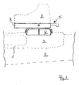
- a merely indicated weapon 2 is shown in partial schematic side view in dashed lines.
- a mounting plate 4 is attached at the front head 3 of the closure housing.
- a device 5 according to the invention is arranged and locked there.
- a target device 6, which is indicated only schematically, is fastened on the device 5.
- the mounting plate 4 is bolted to the closure housing 1 of the weapon 2 in a merely indicated manner.
- the mounting plate 4 is provided with a continuous recess 6, which is delimited by two mutually opposite, substantially parallel edges 7, 7 'or oppositely curved edges 8, 8'.
- the edges 7 and 7 'extending parallel to the longitudinal axis of the recess 6 extends transversely to the longitudinal axis of the weapon. 2
- the device 5 has a base plate 9, on which the target device 6 is screwed.
- a pivot pin 10 is provided, which relative to the base plate by means of an actuating element in the form of a pivoting lever 11 from a first position (Fig. 3), which corresponds to the mounting position, in which the device removed from the weapon or placed on this can be in a second position (Fig. 4), in which the device is locked to the weapon, can be pivoted.
- the head of the Pivotzpfens 10 which corresponds in its outer contour substantially the inner contour of the recess 6, in this recess and is locked by turning in the position shown in Fig. 4 in the manner of a backgrip.
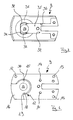
- Fig. 5 the device 5 from above, that is, the target device 6 facing side, shown.
- the pivot lever 11 is formed and supported in a recess 12 formed in the surface of the base plate such that the surface of the pivot lever 11 is substantially flush with the surface of the base plate 9, so that a substantially planar mounting surface for fixing the target device 6 is obtained ,
- protruding centering pins are provided on the base plate 9 from the surface, which can serve to fix the position of the target device.
- threaded holes 14 are provided in the base plate, in which the target device can be screwed.
- the recess 12 has a circular-cylindrical bearing area 15 and an outwardly opening pivot area 16.
- the bearing area 15 is concentric with the opening 17, which serves for the passage of the shaft of Pivotzapfens 10 and coaxial with the pivot axis of Pivotzpfens 10, formed and has a first circular cylindrical portion 18 with a larger diameter and a second circular cylindrical portion 19 with a smaller diameter.
- the surfaces of the regions 18 and 19 extending substantially parallel to the plane of the drawing are designed as axial bearing surfaces and the peripheral surfaces of the regions 18 and 19 as radial bearing surfaces for the pivot lever 11.
- the pivoting lever 11 which is shown in an enlarged view in FIGS. 8 to 10, initially has a central bearing area 20 and an integrally formed thereon lever element 21.
- the central storage area 20 is provided with two zueinender concentric shoulders 22 and 23 corresponding in height and diameter of the areas 18 and 19 of the recess of the base plate 9 such that the pivot lever 11 with its central storage area 20 in the recess 16 can be introduced and rotated there or pivotable to the corresponding axial and radial bearing surfaces can be brought abutting the plant.
- a cylindrical driving pin 24 is arranged, which passes through the opening 17 with at least slightly radial clearance.
- the driving pin is provided with a slot-like, the driver pin 24 in the radial direction completely through recess 25.
- the pivot pin 10 (see in particular Fig. 11) has a head 26 and a shaft 27 integrally formed thereon.
- the shaft 27 of the Pivotzpfens 10 has a width which corresponds substantially to the width of the recess 25 in the driving pin 24, so that the shaft of Pivotzapfens is substantially free of play torque-transmitting inserted in the driving pin.
- the Pivotzapfen 10 is provided with the entire Pivotzapfen sweeping, open on both sides threaded bore 28.
- the driving pin 24 of the pivot lever including the bearing portion 20 is provided with a continuous, open on both sides bore 29 which extends coaxially to the threaded bore 28.
- a fixing screw (not shown) can be inserted from the upper side (FIG. 9) and screwed into the threaded bore 28 in particular in the case of axial fixing of the pivot pin shaft in the driving pin.
- the fastening screw can be countered in any position, resulting in a simple adjustment of the height or axial length of the effective Pivotzapfens and thus an adaptation to different mounting plate thickness.
- a bore 30 is formed in the base plate 9, which extends from the outer surface continuously to the peripheral surface of the region 18 of the recess 12.
- this bore 30 is an unillustrated spring-loaded locking element arranged that in a complementary shape and function complementary recess in the peripheral surface of the region 22 of the pivot lever is engageable. This allows a slight locking in the corresponding end position of the pivot lever.
- the side of the base plate 9 facing the mounting plate 4 has a substantially annular abutment surface 31 which is at least slightly raised relative to the base plate 9 and which is arranged concentrically to the pivot axis and to the defined support on the mounting plate 4 serves.
- the outer contour substantially corresponds to the inner contour of the recess 6 of the mounting plate 4 so that when mounted on the mounting plate 4 base plate 9 of the collar-like paragraph 32 in Substantially positively engages in the recess 6.
- Both the arc-shaped curved portions 33 and the stop edges 34 are applied to the associated surfaces of the recess 6 and thereby cause a positional fixation of the base plate in the plane of the plate, in particular a reliable protection against rotation.
- the recess 6 a portion of the collar-like paragraph is formed in its position changeable in the embodiment shown.
- the base plate 9 has a slot-like linear guide 35, whose longitudinal edges 36 and 37 widen in the manner of a backgrip and form a dovetailed guide as a whole.
- a shape and function complementary slide 38 which carries at its front edge a portion 39 of the collar-like paragraph, can be inserted into the guide and there substantially freely positioned. By the position of the slider 38, the width b of the collar-like shoulder 32 can be adjusted in a simple manner.
- the slider 38 is provided with a threaded bore 40, which is merely indicated in FIG. 12 a) and extends in the direction of the slide axis.
- a threaded spindle 41 which is provided at its first end with a right-hand thread and at its second end with a left-hand thread, is screwed with its first end into the threaded bore 40 of the slider. With its second end, the threaded spindle 41 engages in a continuous threaded bore 42 of a lock nut 43, which is fastened by means of two fastening screws 44 and 45 via the threaded holes 46 and 47 in the base plate of this.
- the threaded spindle 41 by means of an Allen wrench, which engages in the threaded bore 42 of the lock nut 43 from the outside, actuated, thereby indicated displacement of the slider and thus an adjustment of the collar-like paragraph.
Landscapes
- Engineering & Computer Science (AREA)
- General Engineering & Computer Science (AREA)
- Pivots And Pivotal Connections (AREA)
- Input Circuits Of Receivers And Coupling Of Receivers And Audio Equipment (AREA)
- Lighters Containing Fuel (AREA)
- Dry Shavers And Clippers (AREA)
Applications Claiming Priority (1)
| Application Number | Priority Date | Filing Date | Title |
|---|---|---|---|
| DE102006011569A DE102006011569A1 (de) | 2006-03-10 | 2006-03-10 | Vorrichtung zur Befestigung eines Zusatzteils an einer Waffe |
Publications (2)
| Publication Number | Publication Date |
|---|---|
| EP1832835A1 true EP1832835A1 (fr) | 2007-09-12 |
| EP1832835B1 EP1832835B1 (fr) | 2010-04-28 |
Family
ID=38164537
Family Applications (1)
| Application Number | Title | Priority Date | Filing Date |
|---|---|---|---|
| EP07004870A Not-in-force EP1832835B1 (fr) | 2006-03-10 | 2007-03-09 | Dispositif de fixation d'un accessoire sur une arme |
Country Status (3)
| Country | Link |
|---|---|
| EP (1) | EP1832835B1 (fr) |
| AT (1) | ATE466248T1 (fr) |
| DE (2) | DE102006011569A1 (fr) |
Cited By (9)
| Publication number | Priority date | Publication date | Assignee | Title |
|---|---|---|---|---|
| US10126094B2 (en) | 2016-05-12 | 2018-11-13 | Bravo Company Mfg, Inc. | Firearm handguard assembly |
| USD844091S1 (en) | 2016-10-20 | 2019-03-26 | Bravo Company Mfg, Inc. | Firearm handguard |
| US10260841B2 (en) | 2016-10-20 | 2019-04-16 | Bravo Company Mfg, Inc. | Firearm accessory mounting system |
| US10260838B1 (en) | 2016-10-20 | 2019-04-16 | Bravo Company Mfg, Inc. | Firearm handguard |
| US10295304B1 (en) | 2016-05-12 | 2019-05-21 | Bravo Company Mfg, Inc. | Firearm handguard assembly |
| US10551145B2 (en) | 2017-10-18 | 2020-02-04 | Bravo Company Mfg, Inc. | Modular key-slot accessory mounting system for a firearm |
| US10900743B2 (en) | 2016-05-12 | 2021-01-26 | Bravo Company Mfg, Inc. | Firearm handguard assembly |
| USD912189S1 (en) | 2019-04-29 | 2021-03-02 | Bravo Company Mfg, Inc. | Firearm handguard |
| US10962332B2 (en) | 2019-04-11 | 2021-03-30 | Smith & Wesson Inc. | Mounting mechanism |
Families Citing this family (4)
| Publication number | Priority date | Publication date | Assignee | Title |
|---|---|---|---|---|
| US8925236B1 (en) * | 2014-04-03 | 2015-01-06 | Magpul Industries Corp. | Firearm accessory mounting interface |
| US9921029B2 (en) | 2014-01-10 | 2018-03-20 | Magpul Industries Corp. | Connector |
| US9239210B2 (en) | 2014-04-03 | 2016-01-19 | Magpul Industries Corp. | Firearm accessory mounting interface |
| US9239209B2 (en) | 2014-04-03 | 2016-01-19 | Magpul Industries, Corp. | Firearm accessory mounting interface |
Citations (4)
| Publication number | Priority date | Publication date | Assignee | Title |
|---|---|---|---|---|
| GB735414A (en) * | 1952-10-10 | 1955-08-17 | Olov Birger Larsson | Improvements in detachable sight mounting means for firearms |
| US4205473A (en) | 1978-09-01 | 1980-06-03 | Wilson Hugh R | Telescope mount for firearms |
| DE10335821A1 (de) * | 2003-07-28 | 2005-03-10 | Heckler & Koch Gmbh | Montageeinrichtung |
| US20060010758A1 (en) * | 2003-01-27 | 2006-01-19 | S.A.T. Swiss Arms Technology Ag | Device for mounting a telescopic sight on a weapon |
Family Cites Families (1)
| Publication number | Priority date | Publication date | Assignee | Title |
|---|---|---|---|---|
| DE10305228A1 (de) * | 2003-02-08 | 2004-08-19 | Otto Repa | Zielfernrohrmontage |
-
2006
- 2006-03-10 DE DE102006011569A patent/DE102006011569A1/de not_active Withdrawn
-
2007
- 2007-03-09 EP EP07004870A patent/EP1832835B1/fr not_active Not-in-force
- 2007-03-09 AT AT07004870T patent/ATE466248T1/de active
- 2007-03-09 DE DE502007003558T patent/DE502007003558D1/de active Active
Patent Citations (4)
| Publication number | Priority date | Publication date | Assignee | Title |
|---|---|---|---|---|
| GB735414A (en) * | 1952-10-10 | 1955-08-17 | Olov Birger Larsson | Improvements in detachable sight mounting means for firearms |
| US4205473A (en) | 1978-09-01 | 1980-06-03 | Wilson Hugh R | Telescope mount for firearms |
| US20060010758A1 (en) * | 2003-01-27 | 2006-01-19 | S.A.T. Swiss Arms Technology Ag | Device for mounting a telescopic sight on a weapon |
| DE10335821A1 (de) * | 2003-07-28 | 2005-03-10 | Heckler & Koch Gmbh | Montageeinrichtung |
Cited By (15)
| Publication number | Priority date | Publication date | Assignee | Title |
|---|---|---|---|---|
| US10295304B1 (en) | 2016-05-12 | 2019-05-21 | Bravo Company Mfg, Inc. | Firearm handguard assembly |
| US10126094B2 (en) | 2016-05-12 | 2018-11-13 | Bravo Company Mfg, Inc. | Firearm handguard assembly |
| US10900743B2 (en) | 2016-05-12 | 2021-01-26 | Bravo Company Mfg, Inc. | Firearm handguard assembly |
| US11686551B2 (en) | 2016-05-12 | 2023-06-27 | Bravo Company Mfg, Inc. | Firearm handguard assembly |
| US11248874B2 (en) | 2016-05-12 | 2022-02-15 | Bravo Company Mfg, Inc. | Firearm handguard assembly |
| USD919034S1 (en) | 2016-10-20 | 2021-05-11 | Bravo Company Mfg, Inc. | Firearm handguard |
| USD844091S1 (en) | 2016-10-20 | 2019-03-26 | Bravo Company Mfg, Inc. | Firearm handguard |
| US10260841B2 (en) | 2016-10-20 | 2019-04-16 | Bravo Company Mfg, Inc. | Firearm accessory mounting system |
| US10260838B1 (en) | 2016-10-20 | 2019-04-16 | Bravo Company Mfg, Inc. | Firearm handguard |
| USD872218S1 (en) | 2016-10-20 | 2020-01-07 | Bravo Company Mfg, Inc. | Firearm handguard |
| USD879904S1 (en) | 2016-10-20 | 2020-03-31 | Bravo Company Mfg, Inc. | Firearm handguard |
| US10551145B2 (en) | 2017-10-18 | 2020-02-04 | Bravo Company Mfg, Inc. | Modular key-slot accessory mounting system for a firearm |
| US11125530B2 (en) | 2017-10-18 | 2021-09-21 | Bravo Company Mfg, Inc. | Modular key-slot accessory mounting system for a firearm |
| US10962332B2 (en) | 2019-04-11 | 2021-03-30 | Smith & Wesson Inc. | Mounting mechanism |
| USD912189S1 (en) | 2019-04-29 | 2021-03-02 | Bravo Company Mfg, Inc. | Firearm handguard |
Also Published As
| Publication number | Publication date |
|---|---|
| DE102006011569A1 (de) | 2007-09-13 |
| DE502007003558D1 (de) | 2010-06-10 |
| ATE466248T1 (de) | 2010-05-15 |
| EP1832835B1 (fr) | 2010-04-28 |
Similar Documents
| Publication | Publication Date | Title |
|---|---|---|
| EP1832835B1 (fr) | Dispositif de fixation d'un accessoire sur une arme | |
| EP2339287B1 (fr) | Système de serrage pour des accessoires sur un rail Picatinny | |
| EP1976735B1 (fr) | Dispositif essuie-glace, notamment pour vehicule automobile | |
| DE3530776C2 (fr) | ||
| EP2372202B1 (fr) | Couplage d'un élément de positionnement d'une soupape avec un élément de raccordement d'un mécanisme de commande | |
| EP4136371A1 (fr) | Appareil de réglage pour une installation technologique | |
| EP2009208B1 (fr) | Dispositif de guidage pour un battant mobile | |
| EP2097199B1 (fr) | Dispositif pendulaire et procédé associé | |
| EP1706654A1 (fr) | Bague filetee | |
| EP1767295A2 (fr) | Outil de coupe avec positionnement fin | |
| DE19936951A1 (de) | Verstellpropeller für Sportboote und Sportjachten | |
| DE102018206045B3 (de) | Drehgriffvorrichtung und Sanitärventil | |
| EP3171120B1 (fr) | Dispositif de montage de dispositif de visée sur une arme a feu | |
| DE102010030518A1 (de) | System zur Ausrichtung eines Achsträgeranschlusselements | |
| EP2172610A1 (fr) | Elément de fixation d'une penture | |
| DE102007062499B4 (de) | Feinverstellvorrichtung mit Gewindespindel | |
| WO2004085778A1 (fr) | Penture reglable, notamment pour portes de douche et/ou portes en verre | |
| DE202006004542U1 (de) | Vorrichtung zur Befestigung eines Zusatzteils, insbesondere einer Zieleinrichtung, an einer Waffe | |
| EP2578985B1 (fr) | Connecteur pour garde-main d'un arme de poing | |
| EP1371452A2 (fr) | Dispositif de serrage à genouillère | |
| EP4311903B1 (fr) | Loqueteau pour un agencement de fenêtre ou de porte et agencement de fenêtre ou de porte | |
| DE102016102403B4 (de) | Kipplaufwaffe | |
| DE19750614C2 (de) | Vorrichtung zum Verändern des Verdrängungsvolumens einer hydrostatischen Maschine | |
| DE202013102682U1 (de) | Bidirektionaler Drehmomentschlüssel | |
| EP4148219B1 (fr) | Dispositif pour le montage réglable d'un actionneur linéaire sur une structure supérieure |
Legal Events
| Date | Code | Title | Description |
|---|---|---|---|
| PUAI | Public reference made under article 153(3) epc to a published international application that has entered the european phase |
Free format text: ORIGINAL CODE: 0009012 |
|
| AK | Designated contracting states |
Kind code of ref document: A1 Designated state(s): AT BE BG CH CY CZ DE DK EE ES FI FR GB GR HU IE IS IT LI LT LU LV MC MT NL PL PT RO SE SI SK TR |
|
| AX | Request for extension of the european patent |
Extension state: AL BA HR MK YU |
|
| 17P | Request for examination filed |
Effective date: 20080311 |
|
| 17Q | First examination report despatched |
Effective date: 20080418 |
|
| AKX | Designation fees paid |
Designated state(s): AT BE BG CH CY CZ DE DK EE ES FI FR GB GR HU IE IS IT LI LT LU LV MC MT NL PL PT RO SE SI SK TR |
|
| GRAP | Despatch of communication of intention to grant a patent |
Free format text: ORIGINAL CODE: EPIDOSNIGR1 |
|
| GRAS | Grant fee paid |
Free format text: ORIGINAL CODE: EPIDOSNIGR3 |
|
| GRAA | (expected) grant |
Free format text: ORIGINAL CODE: 0009210 |
|
| AK | Designated contracting states |
Kind code of ref document: B1 Designated state(s): AT BE BG CH CY CZ DE DK EE ES FI FR GB GR HU IE IS IT LI LT LU LV MC MT NL PL PT RO SE SI SK TR |
|
| REG | Reference to a national code |
Ref country code: GB Ref legal event code: FG4D Free format text: NOT ENGLISH |
|
| REG | Reference to a national code |
Ref country code: CH Ref legal event code: EP |
|
| REG | Reference to a national code |
Ref country code: IE Ref legal event code: FG4D Free format text: LANGUAGE OF EP DOCUMENT: GERMAN |
|
| REF | Corresponds to: |
Ref document number: 502007003558 Country of ref document: DE Date of ref document: 20100610 Kind code of ref document: P |
|
| REG | Reference to a national code |
Ref country code: CH Ref legal event code: NV Representative=s name: FREI PATENTANWALTSBUERO AG |
|
| REG | Reference to a national code |
Ref country code: NL Ref legal event code: VDEP Effective date: 20100428 |
|
| LTIE | Lt: invalidation of european patent or patent extension |
Effective date: 20100428 |
|
| PG25 | Lapsed in a contracting state [announced via postgrant information from national office to epo] |
Ref country code: LT Free format text: LAPSE BECAUSE OF FAILURE TO SUBMIT A TRANSLATION OF THE DESCRIPTION OR TO PAY THE FEE WITHIN THE PRESCRIBED TIME-LIMIT Effective date: 20100428 Ref country code: ES Free format text: LAPSE BECAUSE OF FAILURE TO SUBMIT A TRANSLATION OF THE DESCRIPTION OR TO PAY THE FEE WITHIN THE PRESCRIBED TIME-LIMIT Effective date: 20100808 Ref country code: SE Free format text: LAPSE BECAUSE OF FAILURE TO SUBMIT A TRANSLATION OF THE DESCRIPTION OR TO PAY THE FEE WITHIN THE PRESCRIBED TIME-LIMIT Effective date: 20100428 Ref country code: NL Free format text: LAPSE BECAUSE OF FAILURE TO SUBMIT A TRANSLATION OF THE DESCRIPTION OR TO PAY THE FEE WITHIN THE PRESCRIBED TIME-LIMIT Effective date: 20100428 |
|
| REG | Reference to a national code |
Ref country code: IE Ref legal event code: FD4D |
|
| PG25 | Lapsed in a contracting state [announced via postgrant information from national office to epo] |
Ref country code: IS Free format text: LAPSE BECAUSE OF FAILURE TO SUBMIT A TRANSLATION OF THE DESCRIPTION OR TO PAY THE FEE WITHIN THE PRESCRIBED TIME-LIMIT Effective date: 20100828 Ref country code: FI Free format text: LAPSE BECAUSE OF FAILURE TO SUBMIT A TRANSLATION OF THE DESCRIPTION OR TO PAY THE FEE WITHIN THE PRESCRIBED TIME-LIMIT Effective date: 20100428 Ref country code: SI Free format text: LAPSE BECAUSE OF FAILURE TO SUBMIT A TRANSLATION OF THE DESCRIPTION OR TO PAY THE FEE WITHIN THE PRESCRIBED TIME-LIMIT Effective date: 20100428 Ref country code: LV Free format text: LAPSE BECAUSE OF FAILURE TO SUBMIT A TRANSLATION OF THE DESCRIPTION OR TO PAY THE FEE WITHIN THE PRESCRIBED TIME-LIMIT Effective date: 20100428 |
|
| PG25 | Lapsed in a contracting state [announced via postgrant information from national office to epo] |
Ref country code: CY Free format text: LAPSE BECAUSE OF FAILURE TO SUBMIT A TRANSLATION OF THE DESCRIPTION OR TO PAY THE FEE WITHIN THE PRESCRIBED TIME-LIMIT Effective date: 20100519 Ref country code: PL Free format text: LAPSE BECAUSE OF FAILURE TO SUBMIT A TRANSLATION OF THE DESCRIPTION OR TO PAY THE FEE WITHIN THE PRESCRIBED TIME-LIMIT Effective date: 20100428 |
|
| PG25 | Lapsed in a contracting state [announced via postgrant information from national office to epo] |
Ref country code: DK Free format text: LAPSE BECAUSE OF FAILURE TO SUBMIT A TRANSLATION OF THE DESCRIPTION OR TO PAY THE FEE WITHIN THE PRESCRIBED TIME-LIMIT Effective date: 20100428 Ref country code: EE Free format text: LAPSE BECAUSE OF FAILURE TO SUBMIT A TRANSLATION OF THE DESCRIPTION OR TO PAY THE FEE WITHIN THE PRESCRIBED TIME-LIMIT Effective date: 20100428 Ref country code: GR Free format text: LAPSE BECAUSE OF FAILURE TO SUBMIT A TRANSLATION OF THE DESCRIPTION OR TO PAY THE FEE WITHIN THE PRESCRIBED TIME-LIMIT Effective date: 20100729 Ref country code: IE Free format text: LAPSE BECAUSE OF FAILURE TO SUBMIT A TRANSLATION OF THE DESCRIPTION OR TO PAY THE FEE WITHIN THE PRESCRIBED TIME-LIMIT Effective date: 20100428 Ref country code: PT Free format text: LAPSE BECAUSE OF FAILURE TO SUBMIT A TRANSLATION OF THE DESCRIPTION OR TO PAY THE FEE WITHIN THE PRESCRIBED TIME-LIMIT Effective date: 20100830 |
|
| PG25 | Lapsed in a contracting state [announced via postgrant information from national office to epo] |
Ref country code: SK Free format text: LAPSE BECAUSE OF FAILURE TO SUBMIT A TRANSLATION OF THE DESCRIPTION OR TO PAY THE FEE WITHIN THE PRESCRIBED TIME-LIMIT Effective date: 20100428 Ref country code: CZ Free format text: LAPSE BECAUSE OF FAILURE TO SUBMIT A TRANSLATION OF THE DESCRIPTION OR TO PAY THE FEE WITHIN THE PRESCRIBED TIME-LIMIT Effective date: 20100428 Ref country code: RO Free format text: LAPSE BECAUSE OF FAILURE TO SUBMIT A TRANSLATION OF THE DESCRIPTION OR TO PAY THE FEE WITHIN THE PRESCRIBED TIME-LIMIT Effective date: 20100428 |
|
| PLBE | No opposition filed within time limit |
Free format text: ORIGINAL CODE: 0009261 |
|
| STAA | Information on the status of an ep patent application or granted ep patent |
Free format text: STATUS: NO OPPOSITION FILED WITHIN TIME LIMIT |
|
| PG25 | Lapsed in a contracting state [announced via postgrant information from national office to epo] |
Ref country code: IT Free format text: LAPSE BECAUSE OF FAILURE TO SUBMIT A TRANSLATION OF THE DESCRIPTION OR TO PAY THE FEE WITHIN THE PRESCRIBED TIME-LIMIT Effective date: 20100428 |
|
| 26N | No opposition filed |
Effective date: 20110131 |
|
| BERE | Be: lapsed |
Owner name: KILIC, MICHAEL ALI Effective date: 20110331 |
|
| PG25 | Lapsed in a contracting state [announced via postgrant information from national office to epo] |
Ref country code: MC Free format text: LAPSE BECAUSE OF NON-PAYMENT OF DUE FEES Effective date: 20110331 |
|
| GBPC | Gb: european patent ceased through non-payment of renewal fee |
Effective date: 20110309 |
|
| PG25 | Lapsed in a contracting state [announced via postgrant information from national office to epo] |
Ref country code: BE Free format text: LAPSE BECAUSE OF NON-PAYMENT OF DUE FEES Effective date: 20110331 Ref country code: MT Free format text: LAPSE BECAUSE OF FAILURE TO SUBMIT A TRANSLATION OF THE DESCRIPTION OR TO PAY THE FEE WITHIN THE PRESCRIBED TIME-LIMIT Effective date: 20100428 |
|
| PG25 | Lapsed in a contracting state [announced via postgrant information from national office to epo] |
Ref country code: GB Free format text: LAPSE BECAUSE OF NON-PAYMENT OF DUE FEES Effective date: 20110309 |
|
| PG25 | Lapsed in a contracting state [announced via postgrant information from national office to epo] |
Ref country code: LU Free format text: LAPSE BECAUSE OF NON-PAYMENT OF DUE FEES Effective date: 20110309 |
|
| PG25 | Lapsed in a contracting state [announced via postgrant information from national office to epo] |
Ref country code: BG Free format text: LAPSE BECAUSE OF FAILURE TO SUBMIT A TRANSLATION OF THE DESCRIPTION OR TO PAY THE FEE WITHIN THE PRESCRIBED TIME-LIMIT Effective date: 20100728 Ref country code: TR Free format text: LAPSE BECAUSE OF FAILURE TO SUBMIT A TRANSLATION OF THE DESCRIPTION OR TO PAY THE FEE WITHIN THE PRESCRIBED TIME-LIMIT Effective date: 20100428 |
|
| PG25 | Lapsed in a contracting state [announced via postgrant information from national office to epo] |
Ref country code: HU Free format text: LAPSE BECAUSE OF FAILURE TO SUBMIT A TRANSLATION OF THE DESCRIPTION OR TO PAY THE FEE WITHIN THE PRESCRIBED TIME-LIMIT Effective date: 20100428 |
|
| PGFP | Annual fee paid to national office [announced via postgrant information from national office to epo] |
Ref country code: CH Payment date: 20140324 Year of fee payment: 8 |
|
| REG | Reference to a national code |
Ref country code: CH Ref legal event code: PL |
|
| PG25 | Lapsed in a contracting state [announced via postgrant information from national office to epo] |
Ref country code: LI Free format text: LAPSE BECAUSE OF NON-PAYMENT OF DUE FEES Effective date: 20150331 Ref country code: CH Free format text: LAPSE BECAUSE OF NON-PAYMENT OF DUE FEES Effective date: 20150331 |
|
| REG | Reference to a national code |
Ref country code: FR Ref legal event code: PLFP Year of fee payment: 10 |
|
| REG | Reference to a national code |
Ref country code: FR Ref legal event code: PLFP Year of fee payment: 11 |
|
| PGFP | Annual fee paid to national office [announced via postgrant information from national office to epo] |
Ref country code: FR Payment date: 20170323 Year of fee payment: 11 |
|
| PGFP | Annual fee paid to national office [announced via postgrant information from national office to epo] |
Ref country code: AT Payment date: 20170322 Year of fee payment: 11 |
|
| REG | Reference to a national code |
Ref country code: AT Ref legal event code: MM01 Ref document number: 466248 Country of ref document: AT Kind code of ref document: T Effective date: 20180309 |
|
| PG25 | Lapsed in a contracting state [announced via postgrant information from national office to epo] |
Ref country code: AT Free format text: LAPSE BECAUSE OF NON-PAYMENT OF DUE FEES Effective date: 20180309 |
|
| PG25 | Lapsed in a contracting state [announced via postgrant information from national office to epo] |
Ref country code: FR Free format text: LAPSE BECAUSE OF NON-PAYMENT OF DUE FEES Effective date: 20180331 |
|
| PGFP | Annual fee paid to national office [announced via postgrant information from national office to epo] |
Ref country code: DE Payment date: 20190521 Year of fee payment: 13 |
|
| REG | Reference to a national code |
Ref country code: DE Ref legal event code: R119 Ref document number: 502007003558 Country of ref document: DE |
|
| PG25 | Lapsed in a contracting state [announced via postgrant information from national office to epo] |
Ref country code: DE Free format text: LAPSE BECAUSE OF NON-PAYMENT OF DUE FEES Effective date: 20201001 |