EP1832839A1 - Barre téléscopiques à jointures sphériques et éléments de fixation à une machine-outil - Google Patents
Barre téléscopiques à jointures sphériques et éléments de fixation à une machine-outil Download PDFInfo
- Publication number
- EP1832839A1 EP1832839A1 EP07250738A EP07250738A EP1832839A1 EP 1832839 A1 EP1832839 A1 EP 1832839A1 EP 07250738 A EP07250738 A EP 07250738A EP 07250738 A EP07250738 A EP 07250738A EP 1832839 A1 EP1832839 A1 EP 1832839A1
- Authority
- EP
- European Patent Office
- Prior art keywords
- ballbar
- mounting
- tool
- equipment
- mounting component
- Prior art date
- Legal status (The legal status is an assumption and is not a legal conclusion. Google has not performed a legal analysis and makes no representation as to the accuracy of the status listed.)
- Granted
Links
Images



Classifications
-
- B—PERFORMING OPERATIONS; TRANSPORTING
- B23—MACHINE TOOLS; METAL-WORKING NOT OTHERWISE PROVIDED FOR
- B23Q—DETAILS, COMPONENTS, OR ACCESSORIES FOR MACHINE TOOLS, e.g. ARRANGEMENTS FOR COPYING OR CONTROLLING; MACHINE TOOLS IN GENERAL CHARACTERISED BY THE CONSTRUCTION OF PARTICULAR DETAILS OR COMPONENTS; COMBINATIONS OR ASSOCIATIONS OF METAL-WORKING MACHINES, NOT DIRECTED TO A PARTICULAR RESULT
- B23Q15/00—Automatic control or regulation of feed movement, cutting velocity or position of tool or work
-
- B—PERFORMING OPERATIONS; TRANSPORTING
- B24—GRINDING; POLISHING
- B24B—MACHINES, DEVICES, OR PROCESSES FOR GRINDING OR POLISHING; DRESSING OR CONDITIONING OF ABRADING SURFACES; FEEDING OF GRINDING, POLISHING, OR LAPPING AGENTS
- B24B49/00—Measuring or gauging equipment for controlling the feed movement of the grinding tool or work; Arrangements of indicating or measuring equipment, e.g. for indicating the start of the grinding operation
-
- G—PHYSICS
- G01—MEASURING; TESTING
- G01B—MEASURING LENGTH, THICKNESS OR SIMILAR LINEAR DIMENSIONS; MEASURING ANGLES; MEASURING AREAS; MEASURING IRREGULARITIES OF SURFACES OR CONTOURS
- G01B21/00—Measuring arrangements or details thereof, where the measuring technique is not covered by the other groups of this subclass, unspecified or not relevant
- G01B21/02—Measuring arrangements or details thereof, where the measuring technique is not covered by the other groups of this subclass, unspecified or not relevant for measuring length, width, or thickness
- G01B21/04—Measuring arrangements or details thereof, where the measuring technique is not covered by the other groups of this subclass, unspecified or not relevant for measuring length, width, or thickness by measuring coordinates of points
- G01B21/042—Calibration or calibration artifacts
-
- G—PHYSICS
- G05—CONTROLLING; REGULATING
- G05B—CONTROL OR REGULATING SYSTEMS IN GENERAL; FUNCTIONAL ELEMENTS OF SUCH SYSTEMS; MONITORING OR TESTING ARRANGEMENTS FOR SUCH SYSTEMS OR ELEMENTS
- G05B19/00—Program-control systems
- G05B19/02—Program-control systems electric
- G05B19/18—Numerical control [NC], i.e. automatically operating machines, in particular machine tools, e.g. in a manufacturing environment, so as to execute positioning, movement or co-ordinated operations by means of program data in numerical form
- G05B19/401—Numerical control [NC], i.e. automatically operating machines, in particular machine tools, e.g. in a manufacturing environment, so as to execute positioning, movement or co-ordinated operations by means of program data in numerical form characterised by control arrangements for measuring, e.g. calibration and initialisation, measuring workpiece for machining purposes
Definitions
- This invention relates to ballbar equipment, for assessing motion inaccuracies in machine tools.
- a ballbar is a telescopic bar which incorporates a highly sensitive position sensor. Any variation in the length of the bar is detected by the position sensor to provide a signal which can be processed by appropriate software to show any discrepancy between the actual and desired relative motions between the tool holder and the table.
- the mounting components are adapted for use with CNC milling machines that have removable tool holders that can receive the respective mounting component. Furthermore, the mounting components available for use with ballbars are capable only of checking relative movements in the X Y plane, which, in a vertical machining centre, is the plane of the workpiece supporting table.
- the currently available ballbar kits are consequently not suitable for use with horizontal grinding machines (ie grinding machines in which the rotational axis of the grinding wheel is horizontal). Such machines have grinding wheel arbors instead of tool holders. It is not possible to fit existing ballbar mounting components to such arbors. Furthermore, since motion of the grinding wheel towards or away from the workpiece (in the Y axis direction in a horizontal grinding machine) is of fundamental importance in grinding operations, it is desirable to be able to use a ballbar to check for inaccuracies in all three planes.
- ballbar equipment comprising:
- the tool mounting component is preferably adapted for use on a grinding machine, for example a horizontal grinding machine.
- the tool mounting component may be adapted to be mounted on a grinding wheel arbor.
- machine tool is to be interpreted broadly to cover not only milling machines but also grinding machines
- tool holder is to be interpreted broadly as covering any component or apparatus which serves to support a cutting tool, which may include a grinding wheel in a machine tool.
- tool holder is to be interpreted sufficiently broadly to embrace a grinding wheel arbor in a grinding machine.
- the tool mounting component may thus comprise a ring which can be fitted over the grinding wheel arbor of a grinding machine.
- Securing means may be provided for fixing the ring on the arbor, and locking means may be provided on the ring for preventing rotation of the arbor during a ballbar test.
- the locking means may comprise a lug projecting from the ring, and provided with a locking screw for engagement with a fixed part of the machine tool to prevent rotation of the arbor.
- the orthogonal receiving means of the tool mounting component may be provided on a mounting block which is connected to the ring by a connecting rod.
- the table mounting component may comprise a mounting block which is adapted to be secured to the table of the machine tool, the orthogonal receiving means being provided on the mounting block.
- the present invention also provides a method of evaluating a machine tool using ballbar equipment as defined above, which method comprises the steps of:
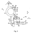
- Figures 1 and 4 show part of a CNC machine tool in the form of a horizontal axis grinding machine including an arbor 2 on which, for use, a grinding wheel is fitted.
- the arbor is connected to a motor and is rotated in operation to perform a grinding operation on a workpiece.
- the grinding machine also has a table 4 on which, in operation, a workpiece is mounted.
- Figures 1 to 4 show the grinding machine set up for the performance of a motion accuracy test, for which the grinding wheel is removed from the arbor 2 and no workpiece is present on the table 4.
- a workpiece is secured to the table 4, and the machine is then set up so as to automatically move the table, and consequently the workpiece, side-to-side beneath a grinding wheel mounted on the arbor 2, in the X direction as indicated in Figure 3.
- the table is also gradually progressed in the Z direction indicated in Figure 1, so that the full surface to be ground is exposed to the grinding wheel.
- the table 4 is elevated, or the grinding wheel is lowered, in the Y direction, as indicated in Figures 1, 3 and 4, in order to remove the required amount of material from the workpiece.
- the grinding operation may utilise simultaneous movement in the X,Y and Z direction.
- the ballbar 74 is supported between a tool holder mounting component 8 and a table mounting component 10.
- the tool holder mounting component 8 comprises a ring 12 which is sized so as to fit snugly over the arbor 2.
- Securing means in the form of a thumbscrew 14 is provided to fix the ring 12 securely on the arbor 2.
- a sector-shaped recess 16 is formed in the ring 12 and, in this recess, sits a lug 18 which is secured to the ring by screws 20.
- the part of the lug 20 which projects beyond the outer circumference of the ring 12 has a threaded hole, and a thumbscrew 22 engages this hole and can be manipulated to engage a fixed part of the grinding machine so as to prevent rotation of the arbor 2 during the ballbar test.
- a rod 24 is screwed into a threaded hole in the ring 12 and, when the tool holder mounting component is fitted to the arbor 2, projects vertically downwardly from the ring 12. At its lower end, the rod 24 carries a mounting block 26, which is shown in more detail in Figures 7 and 8.
- the mounting block is generally in the shape of a cuboid having one edge removed to provide an oblique surface 28.
- the mounting block 26 has a screwthreaded hole 30 in its top surface, which receives the rod 24.
- a screwthreaded hole 32 extends inwardly from the oblique surface 28 to the screwthreaded hole 30 and receives a locking screw which serves to lock the block 26 against rotation on the rod 24.
- the block 26 has three orthogonal surfaces 34, 36 and 38.
- the surfaces 34 and 38 are on mutually perpendicular sides of the block 26, while the surface 36 is on the bottom of the block 26.
- Receiving means in the form of a plain bore 40 extends inwardly from each of the surfaces 34, 36 and 38, and is intersected by a screwthreaded hole 48.
- Each of the bores 40 can receive a supporting element in the form of a ballbar mounting pin 50, as shown in Figures 1, 3 and 4. It will be appreciated that, when the ring 12 is fitted to the arbor 2, and the block 26 is appropriately oriented, the mounting faces 34, 36, 38 will lie perpendicular to the respective X, Y and Z axes.
- the table mounting component 10 comprises a block 52 secured to the table 4 by bolts 54.
- the block 52 is shown in more detail in Figures 5 and 6. It is of generally cuboid shape having a top surface 54 which is provided on two sides with a wall. 56.
- the wall 56 extends upwardly from two mutually perpendicular side faces 58, 60.
- the top surface 54 and the side walls 58 and 60 thus comprise orthogonal mounting surfaces.
- Each of these surfaces 54, 58, 60 is provided with receiving means in the form of a shallow circular depression 62 within which is situated a thin pad 64 of magnetic material. This pad 64 may be omitted where the mounting component 10 is made of a magnetisable material such as steel.
- a supporting element in the form of a holder 66 can be located in any one of the recesses 62, where it is held in place by means of a magnet fitted to the holder 66 which attracts to the pad 64.
- the holder 66 is provided with a mounting pin 68.
- the mounting pin 68 is provided at its free end with a ball 72 of magnetic material such as steel.
- the mounting pin 50 has, at its end away from the block 26, an end surface provided with a recess surrounded by a bearing ring (not shown) having three raised projections.
- the recess contains a magnet (not shown).
- the ballbar 74 extends between the ball 72 and the free end of the mounting pin 50 on the block 26.
- the ballbar 74 has, at its end adjacent the mounting pin 50, a ball 70 of magnetic material such as steel.
- the ball 70 is magnetically attracted to the bearing ring on the mounting pin 50, and seats on the three projections which serve as locating points.
- a reverse arrangement is provided at the opposite end of the ballbar 74, with the ball 72 of the holder 66 being magnetically coupled to a magnet provided in a recess on the end of the ballbar 74, and contacting three locating points on a bearing ring. Consequently, the ends of the ballbar 74 are accurately located with respect to the mounting pins 50 and 68 which, themselves, are rigidly fixed respectively to the arbor 2 and the table 4.
- Figure 1 shows the ballbar and its associated components assembled to perform a test in the XY plane in which the arbor is rotated relatively to the plane about an axis parallel to the Z axis and passing through the ball 72.
- the lower position of the ballbar 74 and the block 26 are shown in solid outline in Figure 1, whereas the uppermost position is shown in dashed outline.
- the ballbar incorporates a position sensor (not shown) which accurately measures any change in the length of the ballbar 74 as the block 26 turns about the ball 72.
- a position sensor (not shown) which accurately measures any change in the length of the ballbar 74 as the block 26 turns about the ball 72.
- Figure 3 shows the equipment set up to perform a test in the YZ plane. It will be appreciated that the blocks 26 and 22 remain in the same positions as shown in Figure 1 on the arbor 2 and the table 4. However, the holder 66 is moved from the mounting face 58, which lies in the XY plane of the machine, to the mounting face 60, which lies in the YZ plane. Also, the mounting pin 50 is moved from the bore 40 in the mounting plane 34 (in the XY plane) to the bore 40 in the mounting plane 38 (also the YZ plane).
- the holder 66 projects outwardly beyond the edge of the table 4 to provide access for the full rotation of the mounting block 26.
- the availability of adequate clearance is also provided by the height of the mounting block 52, and the positioning of the recesses 62 in the upper region of the block, extending into the wall 56.
- Figure 4 shows the equipment set up to perform a test in the XZ plane, in which the mounting cup 66 and the mounting pin 50 are fitted, respectively, the mounting faces 54 and 36.
- the ballbar 74 can be used to perform tests about all three axes of the machine. The tests can be performed relatively easily, since the mounting components 8 and 10 do not have to be moved when setting up the equipment for different measurement planes. Only the mounting pin 50, the holder 66 and the ballbar 74 itself need to be moved.
- the equipment can be used on a grinding machine owing to the construction of the mounting component 8 in the form of a ring 12.
- the ballbar 74 and the holder 66 may be proprietary items, such as are available from Renishaw plc under the designation QC10.
Landscapes
- Engineering & Computer Science (AREA)
- Physics & Mathematics (AREA)
- General Physics & Mathematics (AREA)
- Mechanical Engineering (AREA)
- Human Computer Interaction (AREA)
- Manufacturing & Machinery (AREA)
- Automation & Control Theory (AREA)
- Constituent Portions Of Griding Lathes, Driving, Sensing And Control (AREA)
Applications Claiming Priority (1)
| Application Number | Priority Date | Filing Date | Title |
|---|---|---|---|
| GB0604748A GB2435842A (en) | 2006-03-09 | 2006-03-09 | Ballbar equipment |
Publications (2)
| Publication Number | Publication Date |
|---|---|
| EP1832839A1 true EP1832839A1 (fr) | 2007-09-12 |
| EP1832839B1 EP1832839B1 (fr) | 2008-09-03 |
Family
ID=36241273
Family Applications (1)
| Application Number | Title | Priority Date | Filing Date |
|---|---|---|---|
| EP07250738A Ceased EP1832839B1 (fr) | 2006-03-09 | 2007-02-21 | Barre télescopique à jointures sphériques et éléments de fixation à une machine-outil |
Country Status (4)
| Country | Link |
|---|---|
| US (1) | US7351129B2 (fr) |
| EP (1) | EP1832839B1 (fr) |
| DE (1) | DE602007000102D1 (fr) |
| GB (1) | GB2435842A (fr) |
Families Citing this family (2)
| Publication number | Priority date | Publication date | Assignee | Title |
|---|---|---|---|---|
| US7997001B1 (en) | 2010-06-14 | 2011-08-16 | King Fahd University Of Petroleum And Minerals | Telescopic ball bar gauge |
| CN119200502A (zh) * | 2020-06-17 | 2024-12-27 | 深圳市中图仪器股份有限公司 | 球杆仪 |
Citations (3)
| Publication number | Priority date | Publication date | Assignee | Title |
|---|---|---|---|---|
| EP0258471A1 (fr) * | 1985-03-08 | 1988-03-09 | Yoshiaki Dr. Kakino | Méthode et dispositif pour mesurer des erreurs d'entraînement de machines-outils |
| EP0526056A1 (fr) * | 1991-07-27 | 1993-02-03 | Renishaw Transducer Systems Limited | Appareil de mesure et de calibration |
| EP0786644A2 (fr) * | 1996-01-27 | 1997-07-30 | Renishaw plc | Barre à sphère pour calibrer une machine |
Family Cites Families (6)
| Publication number | Priority date | Publication date | Assignee | Title |
|---|---|---|---|---|
| US4435905A (en) * | 1982-03-15 | 1984-03-13 | The United States Of America As Represented By The United States Department Of Energy | Telescoping magnetic ball bar test gage |
| DE3735075A1 (de) * | 1987-10-16 | 1989-04-27 | Zeiss Carl Fa | Pruefeinrichtung und verfahren zur bestimmung der messunsicherheit von koordinatenmessgeraeten |
| US5430948A (en) * | 1993-07-12 | 1995-07-11 | Vander Wal, Iii; H. James | Coordinate measuring machine certification system |
| TW567941U (en) * | 2003-03-21 | 2003-12-21 | Hon Hai Prec Ind Co Ltd | Fixing device for electronic indicator |
| DE20314680U1 (de) * | 2003-09-20 | 2003-11-20 | Oerlikon Geartec AG, Zürich | Schleifmaschine mit Messsystem und Steuerung zum Bereitstellen eines Meistermessers |
| US6988434B1 (en) * | 2003-12-03 | 2006-01-24 | Elk Premium Building Products, Inc. | Multi-axis tool positioner and related methods |
-
2006
- 2006-03-09 GB GB0604748A patent/GB2435842A/en not_active Withdrawn
-
2007
- 2007-02-21 DE DE602007000102T patent/DE602007000102D1/de active Active
- 2007-02-21 EP EP07250738A patent/EP1832839B1/fr not_active Ceased
- 2007-02-27 US US11/710,970 patent/US7351129B2/en active Active
Patent Citations (3)
| Publication number | Priority date | Publication date | Assignee | Title |
|---|---|---|---|---|
| EP0258471A1 (fr) * | 1985-03-08 | 1988-03-09 | Yoshiaki Dr. Kakino | Méthode et dispositif pour mesurer des erreurs d'entraînement de machines-outils |
| EP0526056A1 (fr) * | 1991-07-27 | 1993-02-03 | Renishaw Transducer Systems Limited | Appareil de mesure et de calibration |
| EP0786644A2 (fr) * | 1996-01-27 | 1997-07-30 | Renishaw plc | Barre à sphère pour calibrer une machine |
Also Published As
| Publication number | Publication date |
|---|---|
| GB2435842A (en) | 2007-09-12 |
| US7351129B2 (en) | 2008-04-01 |
| US20070212981A1 (en) | 2007-09-13 |
| DE602007000102D1 (de) | 2008-10-16 |
| GB0604748D0 (en) | 2006-04-19 |
| EP1832839B1 (fr) | 2008-09-03 |
Similar Documents
| Publication | Publication Date | Title |
|---|---|---|
| US7278222B2 (en) | Method for measuring a program-controlled machine tool | |
| CN109414792B (zh) | 工作机械、加工件的制造方法及加工系统 | |
| EP0545658B1 (fr) | Système automatique de maintenance pour des machines numériques commandées par ordinateur | |
| CN111716147B (zh) | 回转壳体零件壁厚误差精确控制加工装置及方法 | |
| JP2016083729A (ja) | 幾何誤差同定システム、及び幾何誤差同定方法 | |
| CN102107373A (zh) | 加工机械的多功能机内测定装置 | |
| JPS63134151A (ja) | ツール設定位置の検査装置及び検査方法 | |
| CN114061521A (zh) | 工件的内孔外圆精密测量装置 | |
| EP1832839B1 (fr) | Barre télescopique à jointures sphériques et éléments de fixation à une machine-outil | |
| KR20210116650A (ko) | 산업 기계, 편심 특정 장치, 편심 특정 방법, 및 프로그램 | |
| EP3473379B1 (fr) | Station de meulage et procédé de compensation d'axe d'une station de meulage | |
| US20160082561A1 (en) | Test gauge | |
| CN1807020B (zh) | 校准方法和使用这种方法的腐蚀和磨削机床 | |
| CN117760298B (zh) | 主轴箱平行度的检测装置及其检测方法 | |
| US20120017671A1 (en) | Test gauge | |
| CN216523798U (zh) | 工件的内孔外圆精密测量装置 | |
| US4651435A (en) | Compound sine bar and method of setting an angle in a lathe | |
| CN111336899B (zh) | 机床主轴头姿态角多值测量量具及测量方法 | |
| CN112025409B (zh) | 一种检验冲压模具数控加工中的轮廓精度的方法 | |
| JPWO2017126044A1 (ja) | 芯出し用治具および芯出し方法 | |
| CN222520049U (zh) | 便于更换阀芯的配钻装置 | |
| KR20160135616A (ko) | 지그 조립체 및 이를 구비하는 가공장치 | |
| KR20100128414A (ko) | 공작기계용 정밀가공 측정지그 | |
| CN107984282A (zh) | 一种圆盘刀库和刀具更换系统及其更换方法 | |
| KR200147904Y1 (ko) | 피스톤 링 마모 측정지그 |
Legal Events
| Date | Code | Title | Description |
|---|---|---|---|
| PUAI | Public reference made under article 153(3) epc to a published international application that has entered the european phase |
Free format text: ORIGINAL CODE: 0009012 |
|
| AK | Designated contracting states |
Kind code of ref document: A1 Designated state(s): AT BE BG CH CY CZ DE DK EE ES FI FR GB GR HU IE IS IT LI LT LU LV MC NL PL PT RO SE SI SK TR |
|
| AX | Request for extension of the european patent |
Extension state: AL BA HR MK YU |
|
| 17P | Request for examination filed |
Effective date: 20070924 |
|
| 17Q | First examination report despatched |
Effective date: 20071025 |
|
| GRAP | Despatch of communication of intention to grant a patent |
Free format text: ORIGINAL CODE: EPIDOSNIGR1 |
|
| AKX | Designation fees paid |
Designated state(s): DE FR GB |
|
| GRAS | Grant fee paid |
Free format text: ORIGINAL CODE: EPIDOSNIGR3 |
|
| GRAA | (expected) grant |
Free format text: ORIGINAL CODE: 0009210 |
|
| AK | Designated contracting states |
Kind code of ref document: B1 Designated state(s): DE FR GB |
|
| REG | Reference to a national code |
Ref country code: GB Ref legal event code: FG4D |
|
| REF | Corresponds to: |
Ref document number: 602007000102 Country of ref document: DE Date of ref document: 20081016 Kind code of ref document: P |
|
| PLBE | No opposition filed within time limit |
Free format text: ORIGINAL CODE: 0009261 |
|
| STAA | Information on the status of an ep patent application or granted ep patent |
Free format text: STATUS: NO OPPOSITION FILED WITHIN TIME LIMIT |
|
| 26N | No opposition filed |
Effective date: 20090604 |
|
| REG | Reference to a national code |
Ref country code: FR Ref legal event code: PLFP Year of fee payment: 10 |
|
| REG | Reference to a national code |
Ref country code: FR Ref legal event code: PLFP Year of fee payment: 11 |
|
| REG | Reference to a national code |
Ref country code: FR Ref legal event code: CA Effective date: 20170517 |
|
| REG | Reference to a national code |
Ref country code: FR Ref legal event code: PLFP Year of fee payment: 12 |
|
| PGFP | Annual fee paid to national office [announced via postgrant information from national office to epo] |
Ref country code: DE Payment date: 20190227 Year of fee payment: 13 Ref country code: GB Payment date: 20190227 Year of fee payment: 13 |
|
| PGFP | Annual fee paid to national office [announced via postgrant information from national office to epo] |
Ref country code: FR Payment date: 20190225 Year of fee payment: 13 Ref country code: DE Payment date: 20190227 Year of fee payment: 13 |
|
| REG | Reference to a national code |
Ref country code: DE Ref legal event code: R119 Ref document number: 602007000102 Country of ref document: DE |
|
| GBPC | Gb: european patent ceased through non-payment of renewal fee |
Effective date: 20200221 |
|
| PG25 | Lapsed in a contracting state [announced via postgrant information from national office to epo] |
Ref country code: FR Free format text: LAPSE BECAUSE OF NON-PAYMENT OF DUE FEES Effective date: 20200229 Ref country code: DE Free format text: LAPSE BECAUSE OF NON-PAYMENT OF DUE FEES Effective date: 20200901 Ref country code: GB Free format text: LAPSE BECAUSE OF NON-PAYMENT OF DUE FEES Effective date: 20200221 |