EP1832865A1 - Analyseur a infrarouge - Google Patents
Analyseur a infrarouge Download PDFInfo
- Publication number
- EP1832865A1 EP1832865A1 EP05822777A EP05822777A EP1832865A1 EP 1832865 A1 EP1832865 A1 EP 1832865A1 EP 05822777 A EP05822777 A EP 05822777A EP 05822777 A EP05822777 A EP 05822777A EP 1832865 A1 EP1832865 A1 EP 1832865A1
- Authority
- EP
- European Patent Office
- Prior art keywords
- gas
- thermal flow
- infrared
- infrared light
- detection
- Prior art date
- Legal status (The legal status is an assumption and is not a legal conclusion. Google has not performed a legal analysis and makes no representation as to the accuracy of the status listed.)
- Withdrawn
Links
- 0 CCC1C(C*)C(CCC2C(CCC3CC(*)(CC)CCC3)CC(CO)CC(C)(C*)C2)CCC1 Chemical compound CCC1C(C*)C(CCC2C(CCC3CC(*)(CC)CCC3)CC(CO)CC(C)(C*)C2)CCC1 0.000 description 1
Images













Classifications
-
- G—PHYSICS
- G01—MEASURING; TESTING
- G01N—INVESTIGATING OR ANALYSING MATERIALS BY DETERMINING THEIR CHEMICAL OR PHYSICAL PROPERTIES
- G01N21/00—Investigating or analysing materials by the use of optical means, i.e. using sub-millimetre waves, infrared, visible or ultraviolet light
- G01N21/17—Systems in which incident light is modified in accordance with the properties of the material investigated
- G01N21/25—Colour; Spectral properties, i.e. comparison of effect of material on the light at two or more different wavelengths or wavelength bands
- G01N21/31—Investigating relative effect of material at wavelengths characteristic of specific elements or molecules, e.g. atomic absorption spectrometry
- G01N21/35—Investigating relative effect of material at wavelengths characteristic of specific elements or molecules, e.g. atomic absorption spectrometry using infrared light
- G01N21/37—Investigating relative effect of material at wavelengths characteristic of specific elements or molecules, e.g. atomic absorption spectrometry using infrared light using pneumatic detection
Definitions
- the present invention relates to an infrared gas analyzer for detecting a concentration of a measurement component that is contained in sample gas, by utilizing an absorption characteristic of an infrared light of a measurement gas. More particularly, the present invention relates to an infrared gas analyzer capable of conducting a highly accurate measurement operation by removing an influence of external vibration given to the infrared gas analyzer.
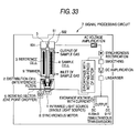
- Fig. 33 is a view showing a structure of an example of the infrared gas analyzer of the related art.
- infrared light emitted from an infrared light source 1 is divided into two by a distribution cell 2 to be respectively incident upon a reference cell 3 and a sample cell 4.
- gas not containing a measurement component, such as inactive gas is filled. Sample gas flows in the sample cell 4. Therefore, infrared light that has been divided into two by the distribution cell 2 is absorbed by the measurement component only on the sample cell 4 side, and reaches a detector 5.
- the detector 5 has two chambers, which are a reference side chamber 501 which receives light from the reference cell 3 and a sample side chamber 502 which receives light from the sample cell 4.
- a thermal flow sensor 51 for detecting a gas flow is attached in a gas flow channel linking the two chambers.
- gas detection gas
- the infrared light is absorbed by the measurement component in the detection gas. Accordingly, the detection gas in the reference side chamber 501 and the detection gas in the sample side chamber 502 are respectively thermally expanded.
- the reference gas in the reference cell 3 does not contain a measurement component, infrared light passing through the reference cell 3 is not absorbed by the measurement component.
- the sample gas in the sample cell 4 contains the measurement component, a portion of the infrared light is absorbed there. Therefore, in the detector 5, a quantity of infrared light incident upon the sample side chamber 502 is reduced, and a thermal expansion of the detection gas in the reference side chamber 501 becomes greater than a thermal expansion of the detection gas in the sample side chamber 502.
- the infrared light is turned on and off by a rotating sector 6. Therefore, the infrared light is repeatedly irradiated and shut off. When the infrared light is shut off, the infrared light is incident upon neither the reference side chamber 501 nor the sample side chamber 502. Accordingly, the detection gas is not expanded.
- a pressure difference is generated periodically according to a concentration of the measurement component that is contained in the sample gas. Accordingly, the detection gas flows back and forth through the gas flow channel arranged between the chambers. The behavior of the detection gas is detected by the thermal flow sensor 51. AC voltage amplification is performed on the detected signal by a signal processing circuit 7 and the amplified signal is outputted as a signal corresponding to the concentration of the measurement component.
- Reference numeral 8 is a synchronous motor that drives the rotating sector 6.
- Reference numeral 9 is a trimmer to adjust a balance between the infrared light incident upon the reference cell 3 and the infrared light incident upon the sample cell 4.
- the concentration of the measurement component that is contained in the sample gas is changed, the quantity of infrared light incident upon the detector 5 (the sample side chamber 502) is changed. Therefore, it is possible to obtain an output signal corresponding to the concentration of the measurement component via the signal processing circuit 7.
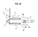
- Fig. 34 is a conceptual view for explaining an influence of vibration.
- the same reference numerals are used to indicate similar parts in Figs. 33 and 34.
- U sig is a moving direction of the detection gas generated in the gas flow channel by the absorption of the infrared light
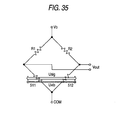
- a first heater wire 511 and a second heater wire 512 of the thermal flow sensor 51 are arranged along the gas moving (flowing) direction U sig with a predetermined distance.
- the first heater wire 511 and the second heater wire 512 generate changes in temperature (resistance) according to the movement of the detection gas.
- Figs. 36(a) and 36(b) are waveform diagrams showing an influence of vibration applied to the infrared gas analyzer.
- Fig. 36(a) is an output signal waveform of the thermal flow sensor 51 in a measurement state, when external vibration is applied to the infrared gas analyzer at time t o .
- Fig. 36(b) is an output signal waveform of the thermal flow sensor 51 in a state that the infrared light source 1 is turned off.
- JP-A-2002-131230 is referred to as the related art.
- An object of the present invention is to provide an infrared gas analyzer capable of conducting a highly accurate measurement operation by removing an influence of external vibration applied to the infrared gas analyzer.
- the present invention provides an infrared gas analyzer, comprising:
- the infrared gas analyzer further comprising:
- the compensation section compensates for a noise component caused by a vibration, based on the respective outputs of the first and the second thermal flow sensors.
- each of the first and the second thermal flow sensors is a bridge circuit having at least two heater wires.
- each of the first and the second thermal flow sensors has at least two heater wires
- the compensation section is a bridge circuit that includes the heater wires of the first and the second thermal flow sensors.
- each of the first and the second thermal flow sensors has at least two heater wires arranged in parallel with respect to a direction for detecting a flow of the detection gas.
- the second thermal flow sensor detects an influence (a noise component) of the vibration applied to the infrared gas analyzer.
- the second thermal flow sensor is not sensitive to a flow (a signal component) of the detection gas corresponding to the concentration of the measurement component. Accordingly, an output of the first thermal flow sensor is compensated by an output of the second thermal flow sensor, thereby it is possible to remove an influence of the external vibration applied to the infrared gas analyzer. Therefore, a highly accurate measurement action can be conducted.
- the present invention provides an infrared gas analyzer, comprising:
- the infrared gas analyzer further comprising:
- the compensation section compensates for a noise component caused by a vibration, based on the respective outputs of the first and the second thermal flow sensors.
- each of the first and the second thermal flow sensors is a bridge circuit having at least two heater wires.
- each of the first and the second thermal flow sensors has at least two heater wires
- the compensation section is a bridge circuit that includes the heater wires of the first and the second thermal flow sensors.
- each of the first and the second thermal flow sensors has at least two heater wires arranged in parallel with respect to the flow direction of the detection gas.
- the gas flow channel has U-shaped portions for respectively making the detection gas being branched at the branch portion flow in a reverse direction
- the detector has a third and a fourth thermal flow sensors arranged in the gas flow channel being folded at the U-shaped portions, in the same direction as the direction of the first and the second thermal flow sensors.
- an influence (a noise component) of the vibration applied to the infrared gas analyzer acts in an opposite polarity. Accordingly, an output of the first thermal flow sensor is compensated by an output of the second thermal flow sensor, thereby it is possible to remove an influence of the external vibration applied to the infrared gas analyzer. Therefore, a highly accurate measurement operation can be conducted.
- the present invention provides an infrared gas analyzer, comprising:
- the infrared gas analyzer further comprising:
- the compensation section compensates for a noise component caused by a vibration, based on the respective outputs of the first and the second thermal flow sensors.
- each of the first and the second thermal flow sensors is a bridge circuit having at least two heater wires.
- each of the first and the second thermal flow sensors has at least two heater wires
- the compensation section is a bridge circuit that includes the heater wires of the first and the second thermal flow sensors.
- each of the first and the second thermal flow sensors has at least two heater wires arranged in parallel with respect to the flow direction of the detection gas.
- an influence (a noise component) of the vibration applied to the infrared gas analyzer acts in an opposite polarity. Accordingly, an output of the first thermal flow sensor is compensated by an output of the second thermal flow sensor, thereby it is possible to remove an influence of the external vibration applied to the infrared gas analyzer. Therefore, a measurement can be highly accurately conducted.
- the present invention provides an infrared gas analyzer, comprising:
- the infrared gas analyzer further comprising:
- a shape of the compensation detector is the same as that of the measurement detector, and the compensation detector does not receive the infrared light.
- the measurement detector and the compensation detector are formed integrally.
- the compensation section obtains a difference between an output of the first thermal flow sensor and an output of the second thermal flow sensor.
- each of the first and the second thermal flow sensors is a bridge circuit having at least two heater wires.
- each of the first and the second thermal flow sensors has at least two heater wires
- the compensation section is a bridge circuit that includes the heater wires of the first and the second thermal flow sensors.
- each of the first and the second thermal flow sensors has at least two heater wires arranged in parallel with respect to the flow direction of the detection gas.
- an influence of the vibration applied to the infrared gas analyzer is detected by the compensation detector and an output of the measurement detector is thereby compensated. Therefore, it is possible to remove an influence of the external vibration given to the infrared gas analyzer and conduct a highly accurate measurement action.
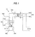
- Fig. 1 is a view showing a configuration of an embodiment of the infrared gas analyzer of the present invention. Same reference numerals are used to indicate similar parts in Fig. 1 and Figs. 33 to 35.
- Reference numerals 1503, 1504 are gas flow channels through which the detection gas flows in a right angle direction.
- a thermal flow sensor 151 for detecting a flow (a signal component: arrow U sig ) of the detection gas corresponding to a concentration of a measurement component is arranged.
- a thermal flow sensor 153 including heater wires 1531, 1532 is arranged in the same direction as that of heater wires 1511, 1512 of the thermal flow sensor 151.
- a flow of the detection gas (a signal component) corresponding to the concentration of the detection component flows in the gas flow channels 1503, 1504, which are bent to form a right angle, as shown by the arrow U sig .
- a flow of the detection gas (a noise component) caused by vibration acts in the gas flow channels 1503, 1504 as shown by the arrow U vib .
- thermal flow sensor 151 detects the noise component U vib together with the signal component U sig .
- the thermal flow sensor 153 detects the noise component U vib , the thermal flow sensor 153 is not sensitive to the signal component U sig .
- Fig. 2 is a circuit diagram showing an example of the specific configuration of a detecting section for detecting outputs of the thermal flow sensors 151, 153.
- reference numerals 111, 112 are bridge circuits for detecting changes in resistance (changes in temperature) of the heater wires 1511, 1512, 1531, 1532 of the thermal flow sensors 151, 153.
- Reference numeral 113 is a compensation section for compensating a noise component caused by vibration, based on a difference between the output V o 11 of the bridge circuit 111 and the output V o 12 of the bridge circuit 112.
- the compensation section 113 of this embodiment obtains the difference while taking account of the polarity of the output V o 11 of the bridge circuit 111 and the polarity of the output V o 12 of the bridge circuit 112.
- Fig. 3 is a view showing a configuration of a second embodiment of the infrared gas analyzer of the present invention. Same reference numerals are used to indicate similar parts in Figs. 1 and 3.
- a bridge circuit is provided in the compensation section 113, and an output signal V o 13 from which a vibration noise component is removed is directly obtained from the bridge circuit.
- Fig. 4 is a circuit diagram showing a specific example of the configuration of the compensation section 113. As shown in Fig. 4, heater wires 1511, 1512, 1531, 1532 of the thermal flow sensors 151, 153 are inserted in different sides of the bridge circuit, and the output signal V o 13 corresponding to a difference between the outputs of two thermal flow sensors 151, 153 is obtained from the output of the bridge circuit.
- the heater wires 1531, 1532 of the thermal flow sensor 153 are inserted in different sides of the bridge circuit in a direction that compensates for noise components superimposed on the heater wires 1511, 1512 of the thermal flow sensor 151. Therefore, two bridge circuits 111, 112 shown in Fig. 2 are omitted and the structure can be made simple.
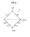
- Fig. 5 is a circuit diagram showing a variation of the bridge circuit in the compensation section 113.
- heater wires 1511, 1512, 1531, 1532 of the thermal flow sensors 151, 153 are inserted in common sides of the bridge circuit. That is, when the heater wires 1531, 1532 of the thermal flow sensor 153 are inserted in the common sides of the bridge circuit in a direction that compensates for the noise components superimposed on the heater wires 1511, 1512 of the thermal flow sensor 151, the same noise removing effect as that of Fig. 4 can be provided.
- Fig. 6 is a view showing a configuration of a third embodiment of the infrared gas analyzer of the present invention. Same reference numerals are used to indicate similar parts in Figs. 1 to 5 and Fig. 6.
- the thermal flow sensors 151, 153 are respectively made up of four heater wires 1511, 1512, 1513, 1514, and 1531, 1532, 1533, 1534.
- heater wire portions arranged on the upstream side and the downstream side of the gas flow respectively include two heater wires. These heater wires are arranged in parallel with respect to the direction of the flow of the detection gas.
- Fig. 7 is a circuit diagram showing a specific example of the configuration of the compensation section (the bridge circuit) 113.
- the heater wires 1511, 1512, 1513, 1514, 1531, 1532, 1533, 1534 of the thermal flow sensors 151, 153 are respectively inserted in the sides of the bridge circuit in a direction that increases the outputs of the respective sensors. Therefore, it is possible to realize the same noise removing effect as that of Fig. 4. Further, it is possible to obtain an output signal V o 15, the magnitude of which is twice as large as that of Fig. 4.
- the number of heater wires of the thermal flow sensors 151, 153 is not necessarily limited to four.
- the outputs of the thermal flow sensors 151, 153 are detected with the bridge circuit.
- positions where the respective heater wires of the thermal flow sensors 151, 153 are inserted are not limited to the above specific embodiment shown in the drawing.
- Fig. 8 is a view showing a configuration of a fourth embodiment of the infrared gas analyzer of the present invention. Same reference numerals are used to indicate similar parts in Fig. 8 and Figs. 33 to 35.
- Reference numerals 2503, 2504 are gas flow channels, and reference numeral 252 is its branch portion. In this structure, the detection gas is made to flow in the reverse directions with respect to the branch portion 252.
- the thermal flow sensor 251 is arranged in one gas flow channel 2503, the thermal flow sensor 251 is arranged.
- the thermal flow sensor 253 including heater wires 2531, 2532 is arranged.
- the heater wires 2531, 2532 of the thermal flow sensor 253 are arranged in the same direction as that of the heater wires 2511, 2512 of the thermal flow sensor 251.
- a flow of the detection gas which corresponds to the concentration of the detection component flows through the gas flow channels 2503, 2504, which are folded back, as shown by the arrow U sig .
- a flow of the detection gas, which is caused by vibration acts as the arrow U vib in the gas flow channels 2503, 2504.
- the detection gas reciprocates in the gas flow channels 2503, 2504 when infrared light is turned on and off.
- the flow of the detection gas is illustrated by the arrow (flow) in one direction. This matter is the same with respect to the flow (the arrow U vib ) of the detection gas caused by vibration.
- two thermal flow sensors 251, 253 are arranged while the directions of the two thermal flow sensors 251, 253 are being made to be the same. Then, concerning the thermal flow sensors 251, 253, with respect to the flow (the arrow U sig ) of the detection gas corresponding to the concentration of the measurement component, an influence of vibration (the arrow U vib ) acts in the reverse phase.
- the arrow U sig and the arrow U vib are in the same direction at the position of the thermal flow sensor 251, and the arrow U sig and the arrow U vib are in the opposite direction at the position of the thermal flow sensor 253.
- Fig. 9 is a circuit diagram showing a specific configuration of a detecting section for detecting outputs of the thermal flow sensors 251, 253.
- reference numerals 211, 212 are bridge circuits for detecting changes in resistance (changes in temperature) of the heater wires 2511, 2512, 2531, 2532 of the thermal flow sensors 251, 253.
- Reference numeral 213 is a compensation section for compensating a noise component caused by vibration, based on a difference between the output V o 21 of the bridge circuit 11 and the output V o 22 of the bridge circuit 212.
- the compensation section 213 of this embodiment while the polarities of the output V o 21 of the bridge circuit 211 and the output V o 22 of the bridge circuit 212 are being taken into account, a difference between them is obtained.
- the movement (the arrow U sig ) of the detection gas corresponding to the concentration of the measurement gas and the movement (the arrow U vib ) of the detection gas caused by vibration are detected.
- the output signal V o 21 contains a vibration noise component.
- the arrows U sig and U vib are directed in the same direction.
- the output signal V o 22 containing the vibration noise component is obtained.
- the arrow U sig and the arrow U vib are directed in the opposite direction.
- Fig. 10 is a view showing a configuration of a fifth embodiment of the infrared gas analyzer of the present invention. Same reference numerals are used to indicate similar parts in Figs. 8 and 10.
- a bridge circuit is provided in the compensation section 213, and a vibration noise component is directly removed from the bridge circuit so as to obtain an output signal V o 23.
- Fig. 11 is a circuit diagram showing an example of the specific configuration of the compensation section 213.
- the heater wires 2511, 2512, 2531, 2532 of the thermal flow sensors 251, 253 are inserted in different sides of the bridge circuit. Therefore, from an output of the bridge circuit, it is possible to obtain an output signal V o 23 corresponding to a difference between the outputs of the two thermal flow sensors 251, 253.
- the heater wires 2531, 2532 of the thermal flow sensor 253 are inserted in different sides of the bridge circuit in a direction that compensates for the noise component superimposed on the heater wires 2511, 2512 of the thermal flow sensor 251 with respect to the influence (noise component) of vibration. Therefore, two bridge circuits 211, 212 shown in Fig. 9 can be omitted and the structure can be made simple.
- Fig. 12 is a circuit diagram showing a variation of the bridge circuit in the compensation section 213.
- the heater wires 2511, 2512, 2531, 2532 of the thermal flow sensors 251, 253 are inserted in common sides of the bridge circuit. That is, when the heater wires 2531, 2532 of the thermal flow sensor 253 are inserted in common sides of the bridge circuit in a direction that compensates for the noise components superimposed on the heater wires 2511, 2512 of the thermal flow sensor 251 with respect to the influence (the noise component) of vibration, the same noise removing effect as that of Fig. 11 can be realized.
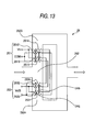
- Fig. 13 is a view showing a configuration of a sixth embodiment of the infrared gas analyzer of the present invention. Same reference numerals are used to indicate similar parts in Figs. 8 to 13.
- the thermal flow sensors 251, 253 are respectively made up of four heater wires 2511, 2512, 2513, 2514 and 2531, 2532, 2533, 2534.
- the heater wire portions arranged on the upstream side and the downstream side of the gas flow respectively include two heater wires, and these heater wires are arranged in parallel with respect to the flow direction of the detection gas.
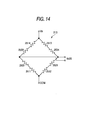
- Fig. 14 is a circuit diagram showing a specific example of the configuration of the compensation section (the bridge circuit) 213.
- the heater wires 2511, 2512, 2513, 2514, 2531, 2532, 2533, 2534 of the thermal flow sensor 251, 253 are inserted in the respective sides of the bridge circuit in a direction that increases the sensor outputs of themselves. Therefore, the same noise removing effect as that of Fig. 11 can be realized. Further, it is possible to obtain an output signal V o 25, the magnitude of which is twice as large as that of Fig. 11. It should be noted that the number of heater wires of the thermal flow sensors 251, 253 is not limited to four.
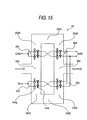
- Fig. 15 is a view showing a configuration of a seventh embodiment of the infrared gas analyzer of the present invention. Same reference numerals are used to indicate similar parts in Figs. 8-14 and 15.
- U-shaped portions 2521, 2522 are provided to the branched gas flow channels 2503, 2504, so that gas flow channels 2505, 2506 through which the detection gas flows in the opposite direction to the gas flow channels 2503, 2504 can be formed, and the thermal flow sensors 254, 255 are arranged in these gas flow channels 2505, 2506.
- thermal flow sensors 251, 253, 254, 255 are arranged in the same direction.
- a relation between the signal component (the arrow U sig ) and the noise component (the arrow U vib ) at each thermal flow sensor position is shown in the drawing.
- Fig. 16 is a view showing a configuration of an eighth embodiment of the infrared gas analyzer of the present invention. Same reference numerals are used to indicate similar parts in Fig. 16 and Figs. 33 and 35.
- a U-shaped portion 352 is provided between the gas flow channels 3503 and 3504. Therefore, a direction of the flow of the detection gas flowing through the gas flow channel 3503 and a direction of the flow of the detection gas flowing through the gas flow channel 3504 are opposite to each other.
- the thermal flow sensor 351 is arranged in one gas flow channel 3503, the thermal flow sensor 351 is arranged.
- the thermal flow sensor 353 including heater wires 3531, 3532 is arranged. The heater wires 3531, 3532 of the thermal flow sensor 353 are arranged in the same direction as that of the heater wires 3511, 3512 of the thermal flow sensor 351.
- a flow of the detection gas caused by vibration acts as the arrow U vib in the gas flow channels 3503, 3504.
- the detection gas reciprocates in the gas flow channels 3503, 3504 when the infrared light is turned on and off.
- the flow of the detection gas is shown by an arrow (flow) in one direction. With respect to the flow (the arrow U vib ) of the detection gas caused by vibration, the circumstances are the same.
- thermal flow sensors 351, 353 When two thermal flow sensors 351, 353 are arranged in the same direction in the gas flow channels 3503, 3504, which are folded back, as shown in Fig. 16, an influence of vibration (the arrow U vib ) acts in an opposite phase with respect to the flow of the detection gas (the arrow U sig ) corresponding to the concentration of the measurement component, in the thermal flow sensors 351, 353.
- the arrow U sig and the arrow U vib are in the same direction at the position of the thermal flow sensor 351, and the arrow U sig and the arrow U vib are in opposite directions at the position of the thermal flow sensor 353.
- Fig. 17 is a circuit diagram showing a specific example of the configuration of a detection section for detecting outputs of the thermal flow sensors 351, 353.
- reference numerals 311, 312 are bridge circuits for detecting changes in resistance (changes in temperature) of the heater wires 3511, 3512, 3531, 3532 of the thermal flow sensors 351, 353.
- Reference numeral 313 is a compensation section for compensating a noise component caused by vibration based on a difference between the output V o 31 of the bridge circuit 311 and the output V o 32 of the bridge circuit 312.
- the compensation section 113 of this embodiment while the polarities of the output V o 31 of the bridge circuit 311 and the output V o 32 of the bridge circuit 312 are taken into account, a difference between them is obtained.
- the movement (the arrow U sig ) of the detection gas corresponding to the concentration of the measurement gas and the movement (the arrow U vib ) of the detection gas caused by vibration are detected, and the output signal V o 31 contains a vibration noise component.
- the arrows U sig and U vib are directed in the same direction.
- the movement (the arrow U sig ) of the detection gas corresponding to the concentration of the measurement gas and the movement (the arrow U vib ) of the detection gas caused by vibration are detected.
- the output signal V o 32 containing the vibration noise component is obtained.
- the arrow U sig and the arrow U vib are directed in opposite directions.
- Fig. 18 is a view showing a configuration of a ninth embodiment of the infrared gas analyzer of the present invention. Same reference numerals are used to indicate similar parts in Figs. 16 and 18.
- a bridge circuit is provided in the compensation section 313, and a vibration noise component is directly removed from the bridge circuit so as to obtain an output signal V o 33.
- Fig. 19 is a circuit diagram showing a specific example of the configuration of the compensation section 313.
- the heater wires 3511, 3512, 3531, 3532 of the thermal flow sensors 351, 353 are inserted in different sides of the bridge circuit. Therefore, from an output of the bridge circuit, it is possible to obtain an output signal V o 33 corresponding to a difference between the outputs of the two thermal flow sensors 351, 353.
- the heater wires 3531, 3532 of the thermal flow sensor 353 are inserted in different sides of the bridge circuit in a direction that compensates for the noise component superimposed on the heater wires 3511, 3512 of the thermal flow sensor 351 with respect to an influence (noise component) of vibration. Therefore, two bridge circuits 311, 312 shown in Fig. 17 can be omitted and the structure can be made simple.
- Fig. 20 is a circuit diagram showing a variation of the bridge circuit of the compensation section 313.
- the heater wires 3511, 3512, 3531, 3532 of the thermal flow sensors 351, 353 are inserted in common sides of the bridge circuit. That is, the heater wires 3531, 3532 of the thermal flow sensor 353 are inserted in common sides of the bridge circuit in a direction so that noise components superimposed on the heater wires 3511, 3512 of the thermal flow sensor 351 can be compensated with respect to an influence (a noise component) of vibration. In this way, the same noise removing effect as that of Fig. 19 can be realized.
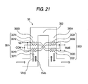
- Fig. 21 is a view showing a configuration of a tenth embodiment of the infrared gas analyzer of the present invention. Same reference numerals are used to indicate similar parts in Fig. 21 and Figs. 33 to 35.
- the thermal flow sensors 351, 353 respectively include four heater wires 3511, 3512, 3513, 3514, and 3531, 3532, 3533, 3534.
- heater wire portions arranged on the upstream side and the downstream side of the gas flow include two heater wires respectively. These heater wires are arranged in parallel with respect to the detection gas flow direction.
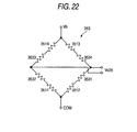
- Fig. 22 is a circuit diagram showing a specific example of the configuration of the compensation section (the bridge circuit) 313.
- the heater wires 3511, 3512, 3513, 3514, 3531, 3532, 3533, 3534 of the thermal flow sensors 351, 353 are inserted in respective sides of the bridge circuit in a direction so that an output of each sensor can be increased. Therefore, the same noise removing effect as that of Fig. 19 can be realized. Further, it is possible to obtain an output signal V o 35, the magnitude of which is twice as large as that of Fig. 19.
- the number of the heater wires of the thermal flow sensors 351, 353 is not necessarily limited to four.
- Fig. 23 is a view showing a configuration of an eleventh embodiment of the infrared gas analyzer of the present invention. Same reference numerals are used to indicate similar parts in Fig. 23 and Figs. 33 to 35.
- Reference numeral 52 is a detector for compensation, and has a thermal flow sensor 53 including heater wires 531, 532.
- the compensation detector 52 has a space in which the detection gas containing the measurement component is filled and formed in a shape similarly as that of the gas flow channel of the detector 5, and a thermal flow sensor 53 is arranged in the space.
- room-shaped spaces which are a little larger than the gas flow channel are exemplarily shown as spaces in which the thermal flow sensors 51, 53 are arranged.
- the shape of the space is not limited to the above specific embodiment.
- the compensation detector 52 is fixed together with the detector 5 or formed integrally with the detector 5 so that the compensation detector 52 can be given an influence of the vibration in the same manner as that of the detector 5. Further, the heater wires 531, 532 of the thermal flow sensor 53 are arranged in the same direction as that of the heater wires 511, 512 of the thermal flow sensor 51. In this connection, infrared light is not incident upon the compensation detector 52.
- Reference numerals 11, 12 are bridge circuits for detecting changes in resistance (changes in temperature) of the heater wires 511, 512, 531, 532 of the thermal flow sensors 51, 53.
- Reference numeral 13 is a compensation section for obtaining a difference between the output of the bridge circuit 11 and the output of the bridge circuit 12.
- Fig. 24 is a circuit diagram showing a specific example of the configuration of the bridge circuits 11, 12. As shown in Fig. 24, the heater wires 511, 512, 531, 532 of the thermal flow sensors 51, 53 are respectively inserted in two sides of the bridge circuits 11, 12. Therefore, changes in resistance caused by a movement of the detection gas are detected as changes in the output voltages V o 1, V o 2.
- a movement (the arrow U sig ) of the detection gas corresponding to the concentration of the measurement gas and a movement (the arrow U vib ) of the detection gas caused by vibration are detected, and the output signal V o 1 contains a vibration noise component.
- the bridge circuit 12 only the movement (the arrow U vib ) of the detection gas caused by vibration is detected and the output signal V o 2 corresponding to it is obtained.
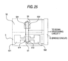
- Fig. 25 is a view showing a configuration of a twelfth embodiment of the infrared gas analyzer of the present invention. Same reference numerals are used to indicate similar parts in Figs. 23 and 25.
- a bridge circuit is provided in the compensation section 13, and an output signal from which a vibration noise component is removed is directly obtained from the bridge circuit.
- Fig. 26 is a circuit diagram showing a specific example of the configuration of the compensation section 13. As shown in Fig. 26, the heater wires 511, 512, 531, 532 of the thermal flow sensors 51, 53 are inserted in different sides of the bridge circuit. Therefore, from an output of the bridge circuit, it is possible to obtain an output signal V o 3 corresponding to a difference between the outputs of the two thermal flow sensors 51, 53.
- the heater wires 531, 532 of the thermal flow sensor 53 are inserted in different sides of the bridge circuit in a direction that compensates for noise components superimposed on the heater wires 511, 512 of the thermal flow sensor 51. Therefore, two bridge circuits 11, 12 shown in Fig. 23 can be omitted and the structure can be made simple.
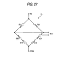
- Fig. 27 is a circuit diagram showing a variation of the bridge circuit of the compensation section 13.
- the heater wires 511, 512, 531, 532 of the thermal flow sensors 51, 53 are inserted in common sides of the bridge circuit. That is, in this embodiment, the heater wires 531, 532 of the thermal flow sensor 53 are inserted in common sides of the bridge circuit in a direction so that noise components superimposed on the heater wires 511, 512 of the thermal flow sensor 51 can be compensated. In this way, the same noise removing effect as that of Fig. 26 can be realized.
- Fig. 28 is a view showing a configuration of a thirteenth embodiment of the infrared gas analyzer of the present invention. Same reference numerals are used to indicate similar parts in Figs. 23-27 and Fig. 28.
- the thermal flow sensors 51, 53 include four heater wires 511, 512, 513, 514, and 531, 532, 533, 534, respectively.
- heater wire portions arranged on the upstream side and the downstream side of the gas flow respectively include two heater wires. These heater wires are arranged in parallel with respect to the direction of the flow of the detection gas.
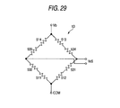
- Fig. 29 is a circuit diagram showing a specific example of the configuration of the compensation section (the bridge circuit) 13.
- heater wires 511, 512, 513, 514, 531, 532, 533, 534 of the thermal flow sensors 51, 53 are respectively inserted in respective sides of the bridge circuit in a direction that increases the sensor output. Therefore, it is possible to realize the same noise removing effect as that of Fig. 26. Further, it is possible to obtain an output signal V o 5, the magnitude of which is twice as large as that of Fig. 26.
- the number of heater wires of the thermal flow sensors 51, 53 is not necessarily limited to four.
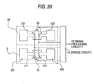
- Fig. 30 is a view showing a configuration of a fourteenth embodiment of the infrared gas analyzer of the present invention. Same reference numerals are used to indicate similar parts in Figs. 23-29 and Fig. 30.
- a space having the same shape as that of the reference side chamber 501 and the sample side chamber 502 of the measurement detector 5 is formed in the compensation detector 52. As described before, infrared light is not incident upon the space of the compensation detector 52.
- the compensation detector 52 is completely the same as the measurement detector 5 in the shape and the size. Accordingly, the detection gas in the compensation detector 52 behaves completely in the same manner as the detection gas in the measurement detector 5 with respect to the applied vibration. Therefore, it is possible to more accurately remove vibration noise.
- Figs. 31 and 32 are views respectively showing a configuration of another embodiment of the infrared gas analyzer of the present invention. Same reference numerals are used to indicate similar parts in Figs. 23-30 and Figs. 31 and 32.
- the space of the measurement detector 5 and the space of the compensation detector 52 are connected by a flow channel.
- the reference side chamber 501 and the sample side chamber 502 of the detector 5 are connected via the space of the compensation detector 52. According to the embodiments shown in Figs.
- the detection gas in the compensation detector 52 when the detection gas in the compensation detector 52 is made to flow, a state of the detection gas in the compensation detector 52 can always be maintained in the same state as that of the detection gas in the detector 5.
- the detection gas in the thermal flow sensor 53 flows.
- the heater wires 531, 532 are arranged in parallel with respect to the flow of the detection gas, the thermal flow sensor 53 does not detect the flow of the detection gas.
Landscapes
- Physics & Mathematics (AREA)
- Spectroscopy & Molecular Physics (AREA)
- Health & Medical Sciences (AREA)
- Life Sciences & Earth Sciences (AREA)
- Chemical & Material Sciences (AREA)
- Analytical Chemistry (AREA)
- Biochemistry (AREA)
- General Health & Medical Sciences (AREA)
- General Physics & Mathematics (AREA)
- Immunology (AREA)
- Pathology (AREA)
- Investigating Or Analysing Materials By Optical Means (AREA)
Applications Claiming Priority (5)
| Application Number | Priority Date | Filing Date | Title |
|---|---|---|---|
| JP2004380571A JP4419835B2 (ja) | 2004-12-28 | 2004-12-28 | 赤外線ガス分析計およびその出力補償方法 |
| JP2004380572A JP4419836B2 (ja) | 2004-12-28 | 2004-12-28 | 赤外線ガス分析計およびその出力補償方法 |
| JP2004380574A JP4419838B2 (ja) | 2004-12-28 | 2004-12-28 | 赤外線ガス分析計およびその出力補償方法 |
| JP2004380573A JP4419837B2 (ja) | 2004-12-28 | 2004-12-28 | 赤外線ガス分析計およびその出力補償方法 |
| PCT/JP2005/023983 WO2006070843A1 (fr) | 2004-12-28 | 2005-12-27 | Analyseur a infrarouge |
Publications (2)
| Publication Number | Publication Date |
|---|---|
| EP1832865A1 true EP1832865A1 (fr) | 2007-09-12 |
| EP1832865A4 EP1832865A4 (fr) | 2008-09-10 |
Family
ID=36614955
Family Applications (1)
| Application Number | Title | Priority Date | Filing Date |
|---|---|---|---|
| EP05822777A Withdrawn EP1832865A4 (fr) | 2004-12-28 | 2005-12-27 | Analyseur a infrarouge |
Country Status (3)
| Country | Link |
|---|---|
| US (1) | US20080093556A1 (fr) |
| EP (1) | EP1832865A4 (fr) |
| WO (1) | WO2006070843A1 (fr) |
Family Cites Families (11)
| Publication number | Priority date | Publication date | Assignee | Title |
|---|---|---|---|---|
| US3560736A (en) * | 1968-10-09 | 1971-02-02 | Mine Safety Appliances Co | Non-dispersive infrared gas analyzer with unbalanced operation |
| US3731092A (en) * | 1971-11-11 | 1973-05-01 | Mine Safety Appliances Co | Non-dispersive infrared gas analyzer having sample and reference beams using flow sensitive detector and with unbalanced operation |
| DE2656487C3 (de) * | 1976-12-14 | 1981-01-29 | Leybold-Heraeus Gmbh, 5000 Koeln | Mikroströmungsfühler für Gase |
| US4860574A (en) * | 1987-06-29 | 1989-08-29 | Yokogawa Electric Corporation | Paramagnetic oxygen analyzer |
| JP3175887B2 (ja) * | 1992-10-27 | 2001-06-11 | 株式会社半導体エネルギー研究所 | 測定装置 |
| JPH09236539A (ja) * | 1995-12-28 | 1997-09-09 | Toray Ind Inc | 赤外線ガス分析計 |
| JPH09229853A (ja) * | 1996-02-22 | 1997-09-05 | Fuji Electric Co Ltd | 赤外線ガス分析計用検出器 |
| DE19924544A1 (de) * | 1998-05-29 | 1999-12-02 | Horiba Ltd | Detektor zur Anwendung in einem Infrarotanalysator, Durchflußdetektor und Verfahren zur Herstellung desselben |
| JPH11344379A (ja) * | 1998-05-29 | 1999-12-14 | Horiba Ltd | 赤外線ガス分析計用検出器 |
| JP2002131230A (ja) * | 2000-10-27 | 2002-05-09 | Horiba Ltd | 赤外線ガス分析計用検出器 |
| JP2004144560A (ja) * | 2002-10-23 | 2004-05-20 | Horiba Ltd | フローセンサ素子およびフローセンサ |
-
2005
- 2005-12-27 WO PCT/JP2005/023983 patent/WO2006070843A1/fr not_active Ceased
- 2005-12-27 US US11/721,824 patent/US20080093556A1/en not_active Abandoned
- 2005-12-27 EP EP05822777A patent/EP1832865A4/fr not_active Withdrawn
Also Published As
| Publication number | Publication date |
|---|---|
| EP1832865A4 (fr) | 2008-09-10 |
| US20080093556A1 (en) | 2008-04-24 |
| WO2006070843A1 (fr) | 2006-07-06 |
Similar Documents
| Publication | Publication Date | Title |
|---|---|---|
| CN111812270A (zh) | 包括环境传感器的传感器装置中的流量测量 | |
| CA2895475C (fr) | Ensemble capteur d'ecoulement a reponse de capteur hybride pouvant etre traitee pour obtenir une mesure de debit volumetrique sur une large plage dynamique | |
| JP2010513846A (ja) | 周期的信号およびIrms計算から雑音を除去するためのフィルタリング技術 | |
| US7823444B2 (en) | Device and process for measuring the velocity of flow of a fluid using pulse signal generated based on feedback | |
| EP1832865A1 (fr) | Analyseur a infrarouge | |
| Zakrzewski et al. | Improving sensitivity and selectivity of SnO/sub 2/gas sensors by temperature variation | |
| US20130211767A1 (en) | Offset compensation for flow sensing devices | |
| JP2004309296A (ja) | 吸光式分析計 | |
| Scarano et al. | A simple hot wire temperature drift correction based on temperature sensitivity applied to a turbulent shear layer | |
| CA2238464A1 (fr) | Detecteur de gaz a montage electrique possedant plusieurs niveaux de sensibilite | |
| CN101091110A (zh) | 红外线气体分析器 | |
| JP4419838B2 (ja) | 赤外線ガス分析計およびその出力補償方法 | |
| JP4419837B2 (ja) | 赤外線ガス分析計およびその出力補償方法 | |
| JP4419836B2 (ja) | 赤外線ガス分析計およびその出力補償方法 | |
| JP4702247B2 (ja) | 赤外線ガス分析計およびその出力補償方法 | |
| JP4702248B2 (ja) | 赤外線ガス分析計およびその出力補償方法 | |
| JP4790330B2 (ja) | ガス濃度測定装置 | |
| US6411380B1 (en) | Detection device for a spectrophotometer | |
| EP3346240A1 (fr) | Débitmètre d'air | |
| US20240393272A1 (en) | Methods for operating thermal conductivity sensors | |
| RU2246099C2 (ru) | Тепловой микрорасходомер газа | |
| CN121594990A (zh) | 一种多工作模式的热式气体微流量传感器 | |
| JP2709586B2 (ja) | 流体変調方式による連続測定形化学発光式ガス分析計 | |
| WO2025158824A1 (fr) | Capteur de débit et programme | |
| SU868521A1 (ru) | Термокондуктометрический детектор |
Legal Events
| Date | Code | Title | Description |
|---|---|---|---|
| PUAI | Public reference made under article 153(3) epc to a published international application that has entered the european phase |
Free format text: ORIGINAL CODE: 0009012 |
|
| 17P | Request for examination filed |
Effective date: 20070508 |
|
| AK | Designated contracting states |
Kind code of ref document: A1 Designated state(s): DE GB |
|
| DAX | Request for extension of the european patent (deleted) | ||
| RBV | Designated contracting states (corrected) |
Designated state(s): DE GB |
|
| A4 | Supplementary search report drawn up and despatched |
Effective date: 20080812 |
|
| STAA | Information on the status of an ep patent application or granted ep patent |
Free format text: STATUS: THE APPLICATION IS DEEMED TO BE WITHDRAWN |
|
| 18D | Application deemed to be withdrawn |
Effective date: 20081108 |