EP1832984B1 - Appareil de traitement d'informations, système de traitement d'informations et procédé de communication de données - Google Patents
Appareil de traitement d'informations, système de traitement d'informations et procédé de communication de données Download PDFInfo
- Publication number
- EP1832984B1 EP1832984B1 EP07251009A EP07251009A EP1832984B1 EP 1832984 B1 EP1832984 B1 EP 1832984B1 EP 07251009 A EP07251009 A EP 07251009A EP 07251009 A EP07251009 A EP 07251009A EP 1832984 B1 EP1832984 B1 EP 1832984B1
- Authority
- EP
- European Patent Office
- Prior art keywords
- traffic
- information processing
- processing apparatus
- data
- class
- Prior art date
- Legal status (The legal status is an assumption and is not a legal conclusion. Google has not performed a legal analysis and makes no representation as to the accuracy of the status listed.)
- Not-in-force
Links
Images


Classifications
-
- G—PHYSICS
- G06—COMPUTING OR CALCULATING; COUNTING
- G06F—ELECTRIC DIGITAL DATA PROCESSING
- G06F13/00—Interconnection of, or transfer of information or other signals between, memories, input/output devices or central processing units
- G06F13/38—Information transfer, e.g. on bus
- G06F13/40—Bus structure
- G06F13/4004—Coupling between buses
- G06F13/4022—Coupling between buses using switching circuits, e.g. switching matrix, connection or expansion network
-
- G—PHYSICS
- G06—COMPUTING OR CALCULATING; COUNTING
- G06F—ELECTRIC DIGITAL DATA PROCESSING
- G06F2213/00—Indexing scheme relating to interconnection of, or transfer of information or other signals between, memories, input/output devices or central processing units
- G06F2213/0026—PCI express
Definitions
- the present invention relates to an information processing apparatus, information processing system, and data communication method, in which a plurality of devices are connected through a high-speed serial switch fabric that can perform a mapping of traffic classes capable of differentiating traffics onto virtual channels.
- PCI peripheral component interconnect
- a parallel-type PCI bus there are problems of racing and skews, for example, and its transfer rate is low at this stage for use in high-speed image forming apparatuses with high image quality.
- a high-speed serial interface such as IEEE 1394 or USB has been considered for use.
- the use of a high-speed serial interface such as IEEE 1394 or USB is suggested for use as an internal interface.
- PCI Express registered trademark
- PCI Express is a succeeding version of the PCI bus standard and is now at the stage of actual use (for example, refer to " Outline of the PCI Express Standard," Takashi Satomi, Interface, July 2003 ).
- this PCI Express system is configured as a data communication network with a tree structure, such as a root complex-switch (arbitrary layer)-device as shown in Fig. 1 in " Outline of the PCI Express Standard," Takashi Satomi, Interface, July 2003 .
- Advanced Switching Interconnect which is a high-speed serial switch fabric based on the PCI Express architecture
- This Advanced Switching Interconnect supports a wider range of applications while still adopting the technology regarding the physical layer and the link layer for PCI Express high-speed serial transmission, and its connection targets are assured to be Chip-to-Chip and Board-to-Board.
- traffic classes are mapped to virtual channels, thereby making it possible to differentiate (assign priorities to) traffics.
- US 2006/0026327 discloses a method, apparatus, and system for controlling data flow operations in a data processing system.
- a traffic class mechanism in conjunction with virtual channel resources are used for such data flow control.
- US 2005/0254085 relates to an image forming system that utilises a high-speed bus to allow for high-speed image processing when timing restrictions and line synchronous transfer exists.
- the embodiments use PCI Express (registered trademark), which is one type of high-speed serial bus.
- PCI Express registered trademark
- the high-speed serial bus means an interface allowing data to be exchanged at high speed (equal to or higher than approximately 100 megabits per second) through serial transmission by using one transmission line.
- a PCI Express bus is a standard expansion bus for use in computers in general as a succeeding version of PCI.
- the PCI Express bus has features, such as low-voltage differential signal transmission, a point-to-point communication channel with independent transmission and reception, packetized split transaction, and high scalability for different link configuration.
- FIG. 1 A configuration example of an existing PCI system is shown in Fig. 1
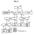
- a configuration example of a PCI Express system is shown in Fig. 2
- a Central Processing Unit 100 an Accelerated Graphics Port (AGP) graphics 101, and a memory 102 are connected to a host bridge 103, to which PCI-X (a standard to which PCI is upwardly-compatible) devices 104a and 104b are connected through a PCI-X bridge 105a and to which a PCI bridge 105b having connected thereto PCI devices 104c and 104d and a PCI bridge 107 having connected thereto a PCI bus slot 106 are connected through a PCI bridge 105c, thereby forming a tree structure.
- PCI-X a standard to which PCI is upwardly-compatible
- a CPU 110 and a memory 111 are connected to a root complex 112, to which a PCI Express graphics 113 is connected through PCI Express 114a and to which a switch 117a having connected thereto an end point 115a and a legacy end point 116a through PCI Express 114b is connected through PCI Express 114c.
- a switch 117c is connected to the root complex 112 through PCI Express 114f.
- the switch 117c has connected thereto a switch 117b through PCI Express 114d and a PCI bridge 119 through PCI Express 114e.
- the switch 117b has connected thereto an end point 115b and a legacy end point 116b, and the PCI bridge 119 has connected thereto a PCI bus slot 118.
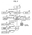
- FIG. 3 An example of a PCI Express platform that can be practically assumed is shown in Fig. 3 , which is an example of application to a desktop/mobile computer.
- a CPU 121 is connected through a CPU host bus 122.
- a memory 123 is connected to a memory hub 124 (is equivalent to a root complex), to which a graphics 125 is connected through PCI Express x16 126a and an Input/Output (I/O) hub 127 with a converting function is connected through PCI Express 126b.
- I/O hub 127 for example, a storage 129 is connected through a Serial ATA 128, a local I/O 131 is connected through a Low Pin Count (LPC) 130, and also USB 2.0 132 and a PCI bus slot 133 are connected.
- LPC Low Pin Count
- the I/O hub 127 has connected thereto a switch 134 through PCI Express 126c.
- the switch 134 has connected thereto a mobile dock 135 through PCI Express 126d, a gigabit Ethernet 136 (Ethernet is a registered trademark) through PCI Express 126e, and an add-in card 137 through PCI Express 126f.
- PCI Express in the PCI Express system, conventional PCI, PCI-X, and AGP are replaced by PCI Express, and a bridge is used for connecting the existing PCI/PCI-X devices.
- a connection between chip sets is also replaced by a PCI Express connection, and the existing buses of IEEE 1394, Serial ATA, USB 2.0 and others are connected to PCI Express through an I/O hub.
- a configuration of a physical layer is shown in Fig. 4 .
- a port is physically in the same semiconductor and is a collection of transmitters/receivers forming a link. Logically, the port means an interface for point-to-point connection between components and the link.
- the transfer rate is set as, for example, 2.5 gigabits per second in one direction.
- a lane is a set of pairs of differential signals with 0.8 volts, and is formed of a signal pair (two signals) on a transmission side and a signal pair (two signals) on a reception side.
- the link is a collection of lanes connecting between two ports and is a dual simplex communication bus between components.
- N 1, 2, 4, 8, 16, 32
- the root complex 112 is positioned at the top of the I/O configuration, and connects the CPU and a memory subsystem to the I/O.
- the root complex is often represented as a "memory hub".
- the root complex 112 (or 124) has one or more PCI Express ports (root ports) (in Fig. 2 , represented as rectangles in the root complex 112), each port forming an independent I/O layer domain.
- the I/O layer domain may be a simple end point (for example, the one on the end point 115a side in Fig. 2 ), or may be formed of many switches and end points (for example, the one on the side of the end point 115b and the switches 117b and 117c in Fig. 2 ).
- the end points 115 are devices having a configuration space header of type 00h (specifically, a device other than a bridge), and are divided into a legacy end point and a PCI Express end point. A significant difference between them is that the PCI Express end point is a Base Address Register (BAR) and does not require an I/O resource, and therefore does not make an I/O request. Neither does the PCI Express end point support a lock request.
- BAR Base Address Register
- the switches 117 connect two or more ports for packet routing among ports. From configuration software, as shown in Fig. 6 , each switch is recognized as a collection of virtual PCI-PCI bridges 141. In the drawing, double-headed arrows represent PCI Express links 114 (or 126), and 142a to 142d represent ports. Of these, the port 142a is an upstream port near the root complex, whilst the ports 142b to 142d are downstream ports away from the root complex.
- PCI Express A connection from PCI Express to PCI/PCI-X is provided. With this, the existing PCI/PCI-X devices can be used on the PCI Express system.
- the conventional PCI architecture has a structure in which a protocol and signaling are closely related to each other as shown in Fig. 7A , and the concept of hierarchy is not there.
- PCI Express has an independent hierarchal structure as shown in Fig. 7B , and specifications are defined for each layer. That is, the structure is such that, between software 151 at the top layer and a mechanical unit 152 at the bottom layer, there are a transaction layer 153, a data link layer 154, and a physical layer 155.
- modulability of each layer is ensured, thereby allowing scalability and reuse of modules. For example, when a new signal coding scheme or transmission medium is adopted, in order to support this, all what is required is to change the physical layer, and neither the data link layer nor the transaction layer has to be changed.
- the main components are the transaction layer 153, the data link layer 154, and the physical layer 155. Each of these layers functions as explained below with reference to Fig. 8 .
- the transaction layer 153 is positioned at the top, and has a function of assembling and disassembling a transaction layer packet (TLP).
- the transaction layer packet (TLP) is used for transmission of transactions, such as read/write and various events. Also, the transaction layer 153 performs flow control using a credit for the transaction layer packet (TLP).
- TLP transaction layer packet
- the outlines of the transaction layer packet (TLP) in each of the layers 153 to 155 are shown in Fig. 9 (details will be explained further below).
- the main function of the data link layer 154 is to ensure data integrity of the transaction layer packet (TLP) through error detection/correction (retransmission) and perform link management. Between data link layers 154, a packet for link management and flow control is exchanged. Such a packet is called a data link layer packet so as to be differentiated from the transaction layer packet (TLP).
- TLP transaction layer packet
- the physical layer 155 includes necessary circuits for interface operation, such as a driver, input buffer, parallel-serial/serial-parallel converter, Phase-Locked Loop (PLL), and impedance matching circuit. Also, as a logical function, the physical layer 155 has a function of initializing and maintaining the interface. Furthermore, the physical layer 155 has a function of making the data link layer 154/transaction layer 153 independent from signal technologies used in an actual link.
- PLL Phase-Locked Loop
- a technology called embedded clock is adopted.
- no clock signal is present and clock timing is embedded in a data signal.
- a clock is extracted.
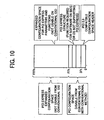
- PCI Express has a configuration space. However, in contrast to the size of the configuration space in the convention PCI being 256 bytes, the size is expanded to 4096 bytes as shown in Fig. 10 . With this, a sufficient space that may be required in future is ensured even for a device (such as a host bridge) requiring many device-specific register sets.
- access to the configuration space is performed through access to a flat memory space (configuration read/write), and the bus/device/function/register number are mapped to memory addresses.
- This space has 256 bytes at the head, which can be accessed as a PCI configuration space even from a Basic Input Output System (BIOS) or the conventional Operating System (OS) through a scheme of using an I/O port.
- BIOS Basic Input Output System
- OS Operating System
- a function of converting the conventional access to PCI Express access is implemented on the host bridge.
- a PCI 2.3-compatible configuration header is formed by 00h to 3Fh.
- the conventional OS and software can be used except for functions obtained through expansion in PCI Express. That is, the software layer in PCI Express has inherited a load store architecture compatible with the existing PCI (a scheme in which a processor directly accesses an I/O register).
- functions obtained through expansion in PCI Express for example, functions of synchronous transfer and Reliability, Availability and Serviceability (RAS)
- RAS synchronous transfer and Reliability, Availability and Serviceability
- the PCI Express can take various form factors (shapes). Specific examples are an add-in card, a plug-in card (Express Card), and Mini PCI Express.
- the transaction layer 153, the data link layer 154, and the physical layer 155 which are main portions of the PCI Express architecture, are respectively explained.
- the main function of the transaction layer 153 is, as explained above, to assemble and disassemble a transaction layer packet (TLP) between the upper software layer 151 and the lower data link layer 154.
- TLP transaction layer packet
- a message space is added (for in-band event notification and general message transmission (exchange) between PCI Express devices, and an interrupt request or confirmation is transmitted by using a message as a "virtual wire"). Therefore, four address spaces are defined. For each space, a transaction type is defined (the memory space, the I/O space, and the configuration space is defined as read/write, whilst the message space is defined as basic (including vendor definition)).
- the header length of the header is 3DW (DW is an abbreviation of double words and 3DW is 12 bytes) or 4DW (16 bytes).
- the header contains information, such as the format of the Transaction Layer Packet (TLP) (the header length and the presence or absence of a payload), the transaction type, a Traffic Class (TC), an attribute, and a payload length.
- the maximum payload length in a packet is 1024 DW (4096 bytes).
- End-to-end Cyclic Redundancy Check is to ensure end-to-end data integrity, and is 32 bits CRC in a part of the Transaction Layer Packet (TLP). ECRC is used because if an error occurs to the Transaction Layer Packet (TLP) inside the switch, the error cannot be detected through link CRC (LCRC) (because the LCRC is recalculated in the TLP where the error occurs).
- TLP Transaction Layer Packet
- LCRC link CRC
- Requests include a request that requires a complete packet and a request that does not require the complete packet.
- Upper software can differentiate traffics by using traffic classes (TCs). For example, video data can be transferred with priority over network data.
- the traffic classes (TC) are classified into eight classes TC0 to TC7.
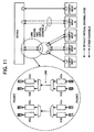
- Virtual Channels are virtual communication buses independent from one another (with a mechanism in which a plurality of independent data flow buffers sharing the same link are used) and each have a resource (a buffer and a queue).
- the virtual channels each perform independent flow control. With this, even if a buffer of one virtual channel is full, a transfer with another virtual channel can be performed. That is, the physically single link can be effectively used by being divided into a plurality of virtual channels. For example, as shown in Fig. 11 , when a root link is divided into links to a plurality of devices through a switch, priorities of traffics to the respective devices can be controlled.
- VC0 is indispensable, and other virtual channels (VC1 to VC7) are implemented according to a tradeoff between cost and performance.
- solid arrow lines represent default virtual channel (VCO) and broken arrow lines represent other virtual channels (VC1 to VC7).
- the Traffic Classes (TCs) are mapped to the Virtual Channels (VCs).
- VC Virtual Channel
- one or plurality of Traffic Classes (TCs) can be mapped (when the number of Virtual Channels (VCs) is small).
- TCs Traffic Classes
- TC0-VC0 mapping is indispensable/fixed, and other mapping is controlled by the upper software.
- the software can control the priorities of transactions.
- FC Flow Control
- the flow control in PCI Express is performed on a credit base (using a mechanism in which the empty state of a reception side buffer is confirmed before starting data transmission to avoid overflow and underflow). That is, the reception side notifies a transmission side of a buffer capacity (a credit value) at the time of initializing the link, and the transmission side then compares the credit value with the length of the packet to be transmitted and transmits the packet only when there is a certain remaining capacity. There are six types of credits.
- Data Link Layer Packet (DLLP) of the data link layer.
- the flow control is applied only to the Transaction Layer Packet (TLP) and is not applied to the Data Link Layer Packet (DLLP) (DLLP can always be transmitted and received).
- the main function of the data link layer 154 is to provide a function of highly reliable Transaction Layer packet (TLP) exchange between two or more components on the link.
- a Transaction Layer Packet (TLP) received from the transaction layer 153 is provided with a sequence number of 2 bytes at its head and an LCRC (link CRC) of 4 bytes at its tail, and is then passed to the physical layer 155 (refer to Fig. 9 ).
- the Transaction Layer Packet (TLP) is stored in a retry buffer and retransmitted to a destination until an acknowledgment (ACK) is received from the destination.
- ACK acknowledgment
- TLP Transaction Layer Packets
- the sequence number and the Link CRC (LCRC) of the Transaction Layer Packet (TLP) received from the physical layer 155 are examined, and if they are normal, the TLP is sent to the transaction layer 153. If there is an error, retransmission is requested.
- LCRC Link CRC
- the Transaction Layer Packet When transmitted from the physical layer, the Transaction Layer Packet (TLP) is automatically divided into Data Link Layer Packets (DLLPs) as shown in Fig. 12 for transmission to each lane.
- a packet generated by the data link layer 154 is called a Data Link Layer Packet (DLLP), and is exchanged between the data link layers 154.
- the Data Link Layer Packet (DLLP) has the following types. Ack/Nak: reception confirmation and retry (retransmission) of TLP; InitFC1/InitFC2/UpdateFC: initialization and update of flow control; and DLLP for Power source management.
- the length of the Data Link Layer Packet is 6 bytes, and is composed of a DLLP type (1 byte) for indicating a type, information specific to the type of the DLLP (3 bytes), and CRC (2 bytes).
- the main function of a logical sub-block 156 in the physical layer 155 shown in Fig. 8 is to convert a packet received from the data link layer 154 to a format that can be transmitted at an electrical sub-block 157. Also, the logical sub-block 156 has a function of controlling and managing the physical layer 155.
- 8B/10B conversion is used for data encoding.
- serial conversion is applied to the converted data and is then transmitted from a least significant bit (LSB) onto a lane.
- LSB least significant bit
- data is allocated to each lane in units of bytes before encoding. In this case, although this looks like a parallel bus at first sight, transferring is independently performed in each lane and, consequently, skewing being a problem in the parallel bus is greatly reduced.
- link states L0/L0s/L1/L2 are defined.
- L0 is a normal mode and power consumption is more lowered from the L0s to L2, but time requiring for recovery to L0 becomes longer.
- Fig. 15 by actively performing active-state power source management in addition to power source management by software, power consumption can be minimized as much as possible.
- the main function of the electrical sub-block 157 in the physical layer 155 is to transmit data serialized by the logical sub-block 156 onto a lane and to receive data from a lane for transfer to the logical sub-block 156.
- a capacitor for AC coupling is mounted at the transmission side of the link. With this, it is not necessary that a DC common mode voltage be the same at the transmission side and the reception side. Therefore, different designs, different semiconductor processes, and different power supply voltages can be used between the transmission side and the reception side.
- the present embodiment uses Advanced Switching Interconnect utilizing the PCI Express technology. As a premise of the present invention, outlines of Advanced Switching Interconnect are explained.
- ASI Advanced Switching Interconnect
- Fig. 16 A relation between a PCI Express and an ASI (Advanced Switching Interconnect) protocol stack is shown in Fig. 16 .
- ASI Advanced Switching Interconnect
- ASI Advanced Switching Interconnect
- PCI transactions developed in computing have been inherited as they are in PCI Express
- ASI Advanced Switching Interconnect
- ASI Advanced Switching Interconnect
- the connection structure has been expanded from the tree structure in PCI Express to allow a more flexible fabric structure, thereby also supporting a multi-CPU environment.
- ASI Advanced Switching Interconnect
- a routing scheme has been significantly improved compared with other standards allowing a similar fabric structure (such as Ethernet (registered trademark) or Infiniband), and therefore the speed has been increased.
- a fabric management function (AS Fabric Mngmnt) shown in Fig. 16 is part of the ASI (Advanced Switching Interconnect) protocol configured by software, supporting various services, such as setting up and removal of connection, event management, monitoring of performance and operation state, redundant route, path nullification, resource assignment, and load leveling.
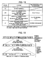
- Fig. 17 is a drawing of an initialization sequence in the fabric management function.
- ASI Advanced Switching Interconnect
- PI Protocol Encapsulation Interface
- ASI Advanced Switching Interconnect
- PCI Express features of PCI Express, such as high speed, bandwidth scalability, expandability of the physical layer with the hierarchical configuration, and data reliability, as well as the following features unique to ASI (Advanced Switching Interconnect):
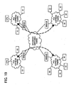
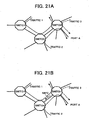
- Such features allow sharing of storages and I/O resources among a plurality of devices as shown in Fig. 19 .
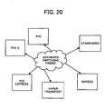
- the use of the ASI (Advanced Switching Interconnect) technology also allows mutual communication as shown in Fig. 20 to be achieved in a simple manner, thereby increasing the speed of communication between devices.
- a local system achieving communication such as TCP/IP at higher speed than that of normal Ethernet processing can be configured.
- redundancy is provided to the system by supporting the fabric structure so as to increase robustness, and also dynamic routing path switching can be performed.
- Advanced Switching Interconnect has the physical layer and the data link layer of PCI Express superposed with an optimized transaction layer, thereby providing various functions.
- Characteristic features of the transaction layer include multilevel Quality of Service (QoS).
- QoS Quality of Service
- the QoS supports 20 virtual channels (VCs) and eight traffic classes (TCs).
- the fabric management function (AS Fabric Mngmnt), which is upper software for controlling ASI (Advanced Switching Interconnect), can differentiate (assign priorities to) traffics by using traffic classes (TCs). For example, video data can be transferred with priority over network data.
- Traffic classes (TC) are classified into eight classes TC0 to TC7
- the virtual Channels are virtual communication buses independent from one another (with a mechanism in which a plurality of independent data flow buffers sharing the same link are used) and each have a resource (a buffer and a queue).
- the virtual channels each perform independent flow control. With this, even if a buffer of one virtual channel is full, a transfer with another virtual channel can be performed. That is, the physically single link can be effectively used by being divided into a plurality of virtual channels.
- the Traffic Classes (TCs) are mapped to the Virtual Channels (VCs).
- VCs Virtual Channels
- TCs Traffic Classes
- TCO-VCO mapping is indispensable/fixed, and other mapping is controlled by the upper software.
- a Congestion state may occur due to the occurrence of excessive traffics.
- a packet response time is increased, thereby posing a problem that it is impossible to keep a certain service level.
- SBFC Status-Based Flow Control
- VCs virtual channels
- ASI Advanced Switching Interconnect
- BVC Bypass Capable Unicast
- OFC Ordered-Only Unicast
- MVC Multicast
- BVC Bypass Capable Unicast
- Multicast As shown in Fig. 24 , an input queue is subjected to multicast output.
- Fig. 25 is a schematic block diagram of a configuration example of an information processing apparatus 1 according a first embodiment of the present invention.
- the information processing apparatus 1 is applied to equipment, such as Multifunction product (MFP).
- MFP Multifunction product
- various end point devices and switch output ports (hereinafter, “devices") are connected together through ASI (Advanced Switching Interconnect) 2, which is a high-speed serial switch fabric.
- ASI Advanced Switching Interconnect
- a system controller 3 a scanner 4 as an image input device, a plotter 5 as an image output device, a first image memory 6 as a storage device, a second image memory 7 as a storage device, an image processing unit 13, an external I/O 9, and an operation panel 10 are connected together.
- the system controller 3 includes a Central Processing Unit (CPU) in charge of controlling the entire apparatus according to a program (software) installed therein, and represents a device portion (printer controller) that performs processes, such as route control and route determination.
- CPU Central Processing Unit
- printer controller printer controller
- the scanner 4 represents a device or unit portion for taking image data based on a document image or the like into the system, and includes, for example, a scanner engine that photoelectrically reads the document image to obtain image data, and others.
- the plotter 5 represents a device or unit portion for print output of image data onto paper or the like, and includes, for example, an electrophotographic plotter (printer) engine, and others.
- various schemes can be used as a printing scheme of the plotter 5, including electrophotography, ink jet, dye-sublimation thermal transfer, silver halide photography, direct thermal recording, and thermofusible transfer.
- the image memories 6 and 7 are Hard Disk Drives (HDDs) or Random Access Memories (RAMs), for example, storing image data read by the scanner 4.
- HDDs Hard Disk Drives
- RAMs Random Access Memories
- the external I/O 9 performs exchange of image data, control data, and other data with another connected device.
- the operation panel 10 includes a touch panel or a display panel, thereby accepting inputs of various instructions to the apparatus.
- the image processing unit 13 performs various image processes to the image data read by the scanner 4 according to a user instruction or the characteristics of the information processing apparatus 1.
- the image processing unit 13 outputs image data after processing to the plotter 5.
- the information processing apparatus 1 gives traffic priorities to various devices for assignment to different Virtual Channels (VCs). This is explained in detail below.
- VCs Virtual Channels
- Figs. 26A and 26B are block diagrams that partially depicts the configuration of the information processing apparatus 1 of Fig. 25 in detail.
- a state is depicted in which the scanner 4, the image processing unit 13, and the plotter 5 are connected through the ASI 2.
- Each device is configured of: a communication core 20 composed of a Transaction Layer (TL), a Data Link Layer (DL), and a Physical layer (PL); a function unique to the device other than the communication core (a data input unit 4a for the scanner 4; an image process unit 13a for the image processing unit 13; and a data output unit 5a for the plotter 5), a data transfer module 30, and a traffic-class setting unit 40.
- TL Transaction Layer
- DL Data Link Layer
- PL Physical layer
- the traffic-class setting unit 40 has a function of assigning a traffic occurring at each data transfer module 30 to a traffic class.
- the Transaction Layer (TL) of the communication core 20 includes a channel setting unit 50 for assigning a Traffic Class (TC) to a Virtual Channel (VC).
- TC Traffic Class
- VC Virtual Channel
- the traffic-class setting unit 40 and the channel setting unit 50 may be configured, as shown in Figs. 26A and 26B , to allow assignment to be freely controlled, or may be configured so that association is narrowed down so as to make a traffic from the data transfer module 30 is uniquely determined with respect to a Virtual Channel (VC).
- VC Virtual Channel
- Fig. 27 is a block diagram of a detailed configuration of the device. The operation of each unit forming the device is explained in detail with reference to Fig. 27 .
- traffics are exemplarily depicted.
- the traffic-class setting unit 40 includes a setting table 40a, a selector 40b, and an arbiter 40c.
- the traffic of each data transfer module 30 can be set at any of the Traffic Classes (TCs).
- TCs Traffic Classes
- a configuration in which the minimum necessary association can be achieved does not pose a problem. In this case, all what is required is to provide only the minimum number of selectors 40b and arbiters 40c.
- Fig. 28 is a schematic drawing of one example of the setting table 40a.
- the setting table 40a stores a Traffic Class (TC) to be set by the traffic-class setting unit 40 for each traffic (for each type of a command of the traffic).
- TC Traffic Class
- a data transfer module (1) and a data transfer module (2) issue a memory write command
- a data transfer module (3) issues a memory read command.
- the Traffic Class (TC) to be associated is determined for each type of the command of the traffic. Therefore, to assign the data transfer module (1) and the data transfer module (2) to TC0, the setting table 40a issues "0", which is a control command to a selector (1) and a selector (2). To assign the data transfer module (3) to TC6, the setting table 40a issues "6", which is a control command to a selector (3).
- the channel setting unit 50 includes a setting table 50a and an arbiter 50b. In the configuration shown in Fig. 27 , only the minimum necessary association can be achieved. Alternatively, so as to be able to set traffics of each Traffic Class (TC) to all Virtual Channels (VCs), a selector may be provided for each Traffic Class (TC). In this case, as with the traffic-class setting unit 40, the channel setting unit 50 includes a setting table, a selector, and an arbiter.
- a control signal is sent from the setting table 40a of the traffic-class setting unit 40 to the selector (1) and an arbiter (00).
- the selector (1) selects an output port based on the received control signal, and notifies the arbiter (00) of the traffic (1).
- the arbiter (00) performs arbitration of the input signal based on the control signal from the setting table 40a, although no conflicting traffic is input in the example shown in Fig. 27 . As a result, the traffic (1) is assigned to TC0.
- a control signal is sent from the setting table 40a of the traffic-class setting unit 40 to the selector (2) and an arbiter (01).
- the selector (2) selects an output port based on the received control signal, and notifies the arbiter (01) of the traffic (2).
- the arbiter (01) performs arbitration of the input signal based on the control signal from the setting table 40a, although no conflicting traffic is input in the example shown in Fig. 27 . As a result, the traffic (2) is assigned to TC1.
- a control signal is sent from the setting table 40a of the traffic-class setting unit 40 to the selector (3) and an arbiter (06).
- the selector (3) selects an output port based on the received control signal, and notifies the arbiter (06) of the traffic (3).
- the arbiter (06) performs arbitration of the input signal based on the control signal from the setting table 40a, although no conflicting traffic is input in the example shown in Fig. 27 . As a result, the traffic (3) is assigned to TC6.
- Traffics of TC0 (traffic (1)) and TC1 (traffic (2)) are input to an arbiter (10).
- the arbiter (10) performs arbitration of the input signal based on the control signal form the setting table 50a.
- the traffics of TC0 (traffic (1)) and TC1 (traffic (2)) are assigned to VC0.
- traffics of TC6 (traffic (3)) and TC7 (no traffic) are input to an arbiter (13).
- the arbiter (13) performs arbitration of the input signal based on the control signal form the setting table 50a, although no conflicting traffic is input in the example shown in Fig. 27 .
- the traffic of TC6 (traffic (3)) is assigned to VC3.
- a traffic class is used to give a priority of data communication.
- the priorities of the data communication are determined by the traffic-class setting unit 40 as: Traffic 2>Traffic 1>Traffics 3, 4, and 5.
- Each Traffic Class (TC) with its priority of data communication determined has a Virtual Channel (VC) mapped by the channel setting unit 50. It is assumed according to the present embodiment that one Traffic Class (TC) is mapped to one Virtual Channel (VC). With this, the fabric management function (AS Fabric Management), which is upper software controlling ASI (Advanced Switching Interconnect), can control the priorities of transactions by using the Traffic Classes (TC).
- AS Fabric Management which is upper software controlling ASI (Advanced Switching Interconnect)
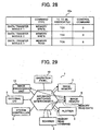
- a copy operation as shown in Fig. 29 is considered, in which data read by the scanner 4 of the information processing apparatus 1 is transferred to the memory 6 and the image data stored in the image memory 6 is then output from the plotter 5.
- a memory write command for the image data is preferably issued after all memory read commands for the image data are issued. This is because, if the memory read command is not prioritized, in view of timing restriction of line synchronous transfer, the memory read command may not be received within a line effective period.
- Traffic 2 (memory read command)>Traffic 1 (memory write Command) .
- a traffic class is set for each traffic at the devices 3 to 10 where a conflict occurs, and a different virtual channel is assigned to each set traffic class to give a priority of data communication, thereby freely expanding the devices 3 to 10 having various traffics of different characteristics with respect to ASI (Advanced Switching Interconnect)2, which is a high-speed serial switch fabric.
- ASI Advanced Switching Interconnect
- Fig. 30 is a schematic block diagram of a configuration example of an information processing system 60 according to the present embodiment.
- information processing apparatuses 61 including a single image memory 6 are coupled via ASI (Advanced Switching Interconnect).
- ASI Advanced Switching Interconnect
- Traffic 2 (memory read command)>Traffic 1 (memory write command).
- Traffic 2 (memory read command)>Traffic 1 (memory write command).
- Traffic 2 (memory read command)>Traffic 1 (memory write command).
- FIG. 34 to 38 A third embodiment of the present invention is explained with reference to Figs. 34 to 38 .
- portions identical to those in the first embodiment or the second embodiment are provided with the same reference numerals and are not explained herein.
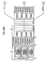
- Fig. 34 is a schematic block diagram of a configuration example of the information processing apparatus 1 according to the present embodiment.
- the information processing apparatus 1 according to the present embodiment is applied to equipment, such as an MFP.
- various end point devices and switch output ports (hereinafter, “devices") are connected together through ASI (Advanced Switching Interconnect) 2, which is a high-speed serial switch fabric.
- ASI Advanced Switching Interconnect
- the system controller 3 the scanner 4, the plotter 5, the image memory 6, a body-information input device 14, a human-body detection sensor 8, an individual detection sensor 11, the operation panel 10, the external I/O 9, a Network Interface Controller (NIC) 12, and the image processing unit 13.
- NIC Network Interface Controller
- the system controller 3 includes a Central Processing Unit (CPU) in charge of controlling the entire apparatus according to a program (software) installed therein, and represents a device portion (printer controller) that performs processes, such as route control and route determination.
- CPU Central Processing Unit
- printer controller printer controller
- the scanner 4 represents a device or unit portion for taking image data based a document image or the like into the system, and includes, for example, a scanner engine that photoelectrically reads the document image to obtain image data, and others.
- the plotter 5 represents a device or unit portion for print output of image data onto paper or the like, and includes, for example, an electrophotographic plotter (printer) engine, and others.
- various schemes can be used as a printing scheme of the plotter 5, including electrophotography, ink jet, dye-sublimation thermal transfer, silver halide photography, direct thermal recording, and thermofusible transfer.
- the image memory 6 is a Hard Disk Drive (HDD) or Random Access Memory (RAM), for example, storing image data read by the scanner 4.
- HDD Hard Disk Drive
- RAM Random Access Memory
- the body-information input device 14 causes a user to enter biometrics information, such as a fingerprint, iris image, face, and vein, for use in personal authentication.
- the human-body detection sensor 8 detects a change in temperature caused by a motion of a person. When it is detected by the human-body detection sensor 8 that nobody is near here, the apparatus is caused to be in a wait state, thereby achieving power saving.
- the individual detection sensor 11 identifies individual information (attributes) through communication with an electronic tag (radiofrequency identification (RFID)) attached to an identification (ID) card owned by the user.
- RFID radiofrequency identification
- the operation panel 10 includes a touch panel or a display panel, thereby accepting inputs of various instructions to the apparatus.
- the external I/O 9 performs exchange of image data, control data, and other data with another connected device.
- the NIC 12 is connected to a network, such as a Local Area Network (LAN) or the Internet, to exchange image data, control data, and other data with another device connected to the network according to a communication protocol.
- a network such as a Local Area Network (LAN) or the Internet
- the image processing unit 13 performs various image processes to the image data read by scanner 4 according to a user instruction or the characteristics of the information processing apparatus 1.
- the image processing unit 13 outputs image data after processing to the plotter 5.
- the information processing apparatus 1 classifies data communication between devices into groups according to a predetermined condition and gives traffic priorities to various devices for assignment to different Virtual Channels (VCs). This is explained in detail below.
- VCs Virtual Channels
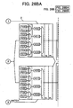
- Figs. 35A and 35B are block diagrams that partially depicts the configuration of the information processing apparatus 1 of Fig. 34 in detail.
- a state is depicted in which the scanner 4, the image processing unit 13, and the plotter 5 are connected through the ASI 2.
- Each device is configured of: a communication core 20 composed of a Transaction Layer (TL), a Data Link Layer (DL), and a Physical layer (PL); a function unique to the device other than the communication core (a data input unit 4a for the scanner 4; an image process unit 13a for the image processing unit 13; and a data output unit 5a for the plotter 5), a data transfer module 30, and a traffic-class setting unit 40.
- TL Transaction Layer
- DL Data Link Layer
- PL Physical layer
- the traffic-class setting unit 40 has a function of assigning a traffic occurring at each data transfer module 30 to a traffic class.
- the Transaction Layer (TL) of the communication core 20 includes a channel setting unit 50 for assigning a Traffic Class (TC) to a Virtual Channel (VC).
- TC Traffic Class
- VC Virtual Channel
- the traffic-class setting unit 40 and the channel setting unit 50 may be configured, as shown in Figs. 35A and 35B , to allow assignment to be freely controlled, or may be configured so that association is narrowed down so as to make a traffic from the data transfer module 30 is uniquely determined with respect to a Virtual Channel (VC).
- VC Virtual Channel
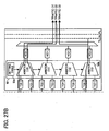
- Fig. 36 is a block diagram of a detailed configuration of the device. The operation of each unit forming the device is explained in detail with reference to Fig. 36 .
- traffics are exemplarily depicted.
- the traffic-class setting unit 40 includes a setting table 40a, a selector 40b, and an arbiter 40c.
- the traffic of each data transfer module 30 can be set at any of the Traffic Classes (TCs).
- TCs Traffic Classes
- a configuration in which the minimum necessary association can be achieved does not pose a problem. In this case, all what is required is to provide only the minimum number of selectors 40b and arbiters 40c.
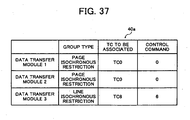
- Fig. 37 is a schematic drawing of one example of the setting table 40a.
- the setting table 40a stores a Traffic Class (TC) to be set by the traffic-class setting unit 40 for each group.
- a data transfer module (1) and a data transfer module (2) are of a traffic group with page isochronous restriction, whilst a data transfer module (3) is of a traffic group with line isochronous restriction.
- the Traffic Class (TC) to be associated is determined for each type of traffic group.
- the setting table 40 issues "0", which is a control command to a selector (1) and a selector (2).
- the setting table 40a issues "6", which is a control command to a selector (3).
- the channel setting unit 50 includes a setting table 50a and an arbiter 50b.
- a selector may be provided for each Traffic Class (TC).
- the channel setting unit 50 includes a setting table, a selector, and an arbiter.
- a control signal is sent from the setting table 40a of the traffic-class setting unit 40 to the selector (1) and an arbiter (00).
- the selector (1) selects an output port based on the received control signal, and notifies the arbiter (00) of the traffic (1).
- the arbiter (00) performs arbitration of the input signal based on the control signal from the setting table 40a, although no conflicting traffic is input in the example shown in Fig. 36 . As a result, the traffic (1) is assigned to TC0.
- a control signal is sent from the setting table 40a of the traffic-class setting unit 40 to the selector (2) and an arbiter (01).
- the selector (2) selects an output port based on the received control signal, and notifies the arbiter (01) of the traffic (2).
- the arbiter (01) performs arbitration of the input signal based on the control signal from the setting table 40a, although no conflicting traffic is input in the example shown in Fig. 36 . As a result, the traffic (2) is assigned to TC1.
- a control signal is sent from the setting table 40a of the traffic-class setting unit 40 to the selector (3) and an arbiter (06).
- the selector (3) selects an output port based on the received control signal, and notifies the arbiter (06) of the traffic (3).
- the arbiter (06) performs arbitration of the input signal based on the control signal from the setting table 40a, although no conflicting traffic is input in the example shown in Fig. 36 . As a result, the traffic (3) is assigned to TC6.
- Traffics of TC0 (traffic (1)) and TC1 (traffic (2)) are input to an arbiter (10).
- the arbiter (10) performs arbitration of the input signal based on the control signal form the setting table 50a.
- the traffics of TC0 (traffic (1)) and TC1 (traffic (2)) are assigned to VC0.
- traffics of TC6 (traffic (3)) and TC7 (no traffic) are input to an arbiter (13).
- the arbiter (13) performs arbitration of the input signal based on the control signal form the setting table 50a, although no conflicting traffic is input in the example shown in Fig. 27 .
- the traffic of TC6 (traffic (3)) is assigned to VC3.
- the Traffic Classes (TCs) of data is classified based on, for example, "isochrony” and "lossless/lossy".
- classification is as listed further below.
- a perishable bit (refer to Fig. 38 ) of an AS packet (allowing packet dropping)
- a lossy function can be turned ON. Therefore, for group classification according to "lossless/lossy", the perishable bit of the AS packet can be referred to. That is, by referring to the perishable bit of the AS packet, lossless/lossy can be easily identified.
- a priority of data communication is given by using a Traffic Class (TC).
- the priorities of the data communication are determined by the traffic-class setting unit 40 as Group A>Group B>Group C>Group D. That is, in data communication between devices, a group with a high isochronous restriction is subjected to data communication with a higher priority. Also, even without isochronous restriction, a lossless group is subjected to data communication with a higher priority.
- traffics with isochronous restriction requiring data transmission within a predetermined period of time are classified as a group.
- the priority of a traffic with isochronous restriction output from such a device as the scanner 4 or the plotter 5 can be made higher than that of a traffic without isochronous restriction. Therefore, isochrony can be ensured for the scanner 4 and the plotter 5, for example, at the time of mixture of traffics.
- traffics with isochronous restriction for each line synchronizing signal are classified as a group. With this, the priority of a traffic with isochronous restriction for each line synchronizing signal from such a device as the scanner 4 or the plotter 5 can be made higher than that of a traffic with isochronous restriction for each page.
- isochrony can be ensured for the scanner 4 and the plotter 5, for example, at the time of mixture of traffics.
- traffics with isochronous restriction for each page are classified as a group. With this, the priority of a traffic with isochronous restriction for each page can be made higher than that of a traffic without isochronous restriction. Therefore, isochrony can be ensured at the time of mixture of traffics.
- traffics without isochronous restriction are classified into groups according to lossless/lossy in a data compression scheme. With this, even without isochronous restriction, a lossless group can be subjected to data communication with priority.
- a Virtual Channel For each Traffic Class (TC) with its priority of data communication determined, a Virtual Channel (VC) is mapped by the channel setting unit 50. It is assumed according to the present embodiment that one Traffic Class (TC) is mapped to one Virtual Channel (VC).
- AS Fabric Mngmnt which is upper software controlling ASI (Advanced Switching Interconnect)
- TC Traffic Classes
- a traffic class is set for each group according to the group table in which group classification is made based on the property of the traffic between devices, and the each set traffic class is assigned to each different virtual channel to give a priority of data communication, thereby freely expanding the devices having various traffics of different characteristics with respect to the high-speed serial switch fabric.
- data communication between devices is classified into groups based on “isochrony” and “lossless/lossy”. This is merely an example, and classification can be arbitrary as long as Traffic Classes (TCs) of different properties can be obtained through classification.
- TCs Traffic Classes
Landscapes
- Engineering & Computer Science (AREA)
- Physics & Mathematics (AREA)
- General Engineering & Computer Science (AREA)
- Theoretical Computer Science (AREA)
- Mathematical Physics (AREA)
- Computer Hardware Design (AREA)
- General Physics & Mathematics (AREA)
- Information Transfer Systems (AREA)
Claims (15)
- Dispositif de traitement d'informations comprenant :une matrice de commutation en série haut débit (2) configurée de manière à mettre en oeuvre une mise en concordance de classe de trafics apte à différencier des trafics sur un canal virtuel, la matrice de commutation en série haut débit (2) connectant une pluralité de dispositifs ;une unité de définition de classe de trafic (40) qui définit, en cas de contention entre les trafics envoyés par des dispositifs connectés à la matrice de commutation en série haut débit (2), la classe de trafic pour chacun des trafics présentant la contention ;une unité de définition de canal (50) qui affecte chacune des classes de trafic définies à des canaux virtuels distincts, et attribue une priorité de communication de données à chacune des classes de trafic définies ; caractérisé en ce qu'il comprend en outre :une table de groupes dans laquelle une communication de données entre les dispositifs est classée en groupes sur la base de propriétés d'un trafic entre les dispositifs, oùl'unité de définition de classe de trafic (40) définit la classe de trafic pour chacun des groupes selon la table de groupes.
- Dispositif de traitement d'informations selon la revendication 1, dans lequel l'unité de définition de classe de trafic (40) définit la classe de trafic pour chacun des types de commande des trafics.
- Dispositif de traitement d'informations selon la revendication 1, dans lequel la matrice de commutation en série haut débit (2) est une matrice de commutation conforme aux normes d'interconnexion de commutation avancée.
- Dispositif de traitement d'informations selon la revendication 1, dans lequel l'unité de définition de canal (50) définit une priorité de la classe de trafic d'un trafic avec restriction isochrone dans des unités de signal de synchronisation de ligne, afin qu'elle soit supérieure à une priorité de la classe de trafic d'un trafic avec restriction isochrone dans des unités de page selon une définition du canal virtuel.
- Dispositif de traitement d'informations selon la revendication 1, dans lequel l'unité de définition de canal (50) définit une priorité de la classe de trafic d'une transaction de lecture en mémoire, afin qu'elle soit supérieure à une priorité de la classe de trafic d'une transaction d'écriture en mémoire selon une définition du canal virtuel.
- Dispositif de traitement d'informations selon la revendication 1, dans lequel des trafics avec restriction isochrone, qui nécessitent une transmission de données pendant une période de temps prédéterminée, sont classés en tant qu'un groupe dans la table de groupes.
- Dispositif de traitement d'informations selon la revendication 6, dans lequel des trafics avec restriction isochrone, dans des unités de signal de synchronisation de ligne, sont classés en tant qu'un groupe dans la table de groupes.
- Dispositif de traitement d'informations selon la revendication 6, dans lequel des trafics avec restriction isochrone, dans des unités de page, sont classés en tant qu'un groupe dans la table de groupes.
- Dispositif de traitement d'informations selon la revendication 6, dans lequel des trafics sans restriction isochrone sont classés dans des groupes selon un critère « sans perte / avec perte » dans un schéma de compression de données dans la table de groupes.
- Dispositif de traitement d'informations selon la revendication 9, dans lequel, lors de la classification des trafics en des groupes sur la base du critère « sans perte / avec perte » dans le schéma de compression de données, l'unité de définition de canal (50) se réfère à un bit périssable dans un paquet d'interconnexion de commutation avancée.
- Dispositif de traitement d'informations selon la revendication 1, dans lequel la pluralité de dispositifs comprend :un dispositif d'entrée d'image lequel lit des données d'image ;un dispositif de stockage lequel stocke des données d'image lues ; etun dispositif de génération en sortie d'images lequel génère en sortie des données d'image stockées.
- Système de traitement d'informations selon la revendication 11, dans lequel, lorsque les données d'image lues par le dispositif d'entrée d'image de l'un des dispositifs de traitement d'informations sont transférées par multidiffusion au dispositif de stockage de chacun des dispositifs de traitement d'informations, et les données d'image stockées dans chaque dispositif de stockage sont générées en sortie à partir du dispositif de génération en sortie d'image de chacun des dispositifs de traitement d'informations, l'unité de définition de canal (50) définit une priorité de communication de données dans les canaux virtuels de la matrice de commutation en série haut débit (2) sous la forme :commande d'écriture en mémoire > commande de lecture en mémoire.
- Système de traitement d'informations selon la revendication 11, dans lequel, lorsque les données d'image lues par le dispositif d'entrée d'image de l'un des dispositifs de traitement d'informations sont transférées au dispositif de stockage, et lorsque le dispositif de génération en sortie d'image de chacun des dispositifs de traitement d'informations émet une commande de lecture en mémoire vers le dispositif de stockage en vue de générer en sortie les données d'image stockées dans le dispositif de stockage, l'unité de définition de canal (50) définit une priorité de communication de données dans les canaux virtuels de la matrice de commutation en série haut débit (2), sous la forme :commande de lecture en mémoire > commande d'écriture en mémoire.
- Système de traitement d'informations selon la revendication 11, dans lequel, lorsque les données d'image lues par le dispositif d'entrée d'image de l'un des dispositifs de traitement d'informations sont transférées au dispositif de stockage, un transfert d'écriture en mémoire par multidiffusion est amené à être occasionné pour les données d'image stockées dans le dispositif de stockage, et les données d'image sont générées en sortie à partir du dispositif de génération en sortie d'image de chacun des dispositifs de traitement d'informations, l'unité de définition de canal (50) définit une priorité de communication de données dans les canaux virtuels de la matrice de commutation en série haut débit (2) sous la forme
commande d'écriture en mémoire > commande de lecture en mémoire. - Procédé de communication de données comprenant les étapes ci-dessous consistant à :définir, en cas de contention entre les trafics envoyés par des dispositifs, la classe de trafic pour chacun des trafics présentant la contention, où les dispositifs connectés à une matrice de commutation en série haut débit (2) sont configurés de manière à mettre en oeuvre une mise en concordance d'une classe de trafic apte à différencier le trafic sur un canal virtuel ;affecter chacune parmi des classes de trafic définies à des canaux virtuels distincts, et affecter une priorité de communication de données à chacune des classes de trafic définies, et caractérisé en ce qu'il comporte l'étape ci-dessous consistant à :classer, dans des groupes en vue de former une table de groupes, une communication de données entre les dispositifs sur la base des propriétés d'un trafic entre les dispositifs, dans laquellela classe de trafic pour chacun des groupes est définie sur la base de la table de groupes.
Applications Claiming Priority (4)
| Application Number | Priority Date | Filing Date | Title |
|---|---|---|---|
| JP2006066364 | 2006-03-10 | ||
| JP2006073413 | 2006-03-16 | ||
| JP2007012023A JP2007282187A (ja) | 2006-03-16 | 2007-01-22 | 情報処理装置、情報処理システムおよびデータ通信方法 |
| JP2007014281A JP2007272871A (ja) | 2006-03-10 | 2007-01-24 | 情報処理装置およびデータ通信方法 |
Publications (2)
| Publication Number | Publication Date |
|---|---|
| EP1832984A1 EP1832984A1 (fr) | 2007-09-12 |
| EP1832984B1 true EP1832984B1 (fr) | 2011-05-04 |
Family
ID=38119687
Family Applications (1)
| Application Number | Title | Priority Date | Filing Date |
|---|---|---|---|
| EP07251009A Not-in-force EP1832984B1 (fr) | 2006-03-10 | 2007-03-12 | Appareil de traitement d'informations, système de traitement d'informations et procédé de communication de données |
Country Status (3)
| Country | Link |
|---|---|
| US (1) | US7664904B2 (fr) |
| EP (1) | EP1832984B1 (fr) |
| DE (1) | DE602007014284D1 (fr) |
Families Citing this family (24)
| Publication number | Priority date | Publication date | Assignee | Title |
|---|---|---|---|---|
| US8223745B2 (en) * | 2005-04-22 | 2012-07-17 | Oracle America, Inc. | Adding packet routing information without ECRC recalculation |
| US7698484B2 (en) * | 2005-09-21 | 2010-04-13 | Ricoh Co., Ltd. | Information processor configured to detect available space in a storage in another information processor |
| US8103993B2 (en) * | 2006-05-24 | 2012-01-24 | International Business Machines Corporation | Structure for dynamically allocating lanes to a plurality of PCI express connectors |
| JP4992296B2 (ja) * | 2006-05-30 | 2012-08-08 | 株式会社日立製作所 | 転送処理装置 |
| US7966440B2 (en) * | 2007-05-14 | 2011-06-21 | Ricoh Company, Limted | Image processing controller and image forming apparatus |
| KR100902773B1 (ko) * | 2007-08-02 | 2009-06-15 | 포항공과대학교 산학협력단 | 무선 통신 시스템에서의 자원 관리 방법 |
| US20090077274A1 (en) * | 2007-09-19 | 2009-03-19 | Advanced Micro Devices | Multi-Priority Communication in a Differential Serial Communication Link |
| US7793030B2 (en) * | 2007-10-22 | 2010-09-07 | International Business Machines Corporation | Association of multiple PCI express links with a single PCI express port |
| US20100002714A1 (en) * | 2008-07-01 | 2010-01-07 | George Madathilparambil George | PCI express network |
| JP2010250665A (ja) * | 2009-04-17 | 2010-11-04 | Toshiba Corp | PCIExpressのTLP処理回路、及びこれを備える中継デバイス |
| US8199759B2 (en) * | 2009-05-29 | 2012-06-12 | Intel Corporation | Method and apparatus for enabling ID based streams over PCI express |
| US8160072B1 (en) * | 2009-12-11 | 2012-04-17 | Brocade Communications Systems, Inc. | Method and system for facilitating QoS zoning in a network |
| JP5577776B2 (ja) * | 2010-03-17 | 2014-08-27 | 株式会社リコー | メモリ制御装置及びマスクタイミング制御方法 |
| US8352630B2 (en) * | 2010-09-01 | 2013-01-08 | Sonus Networks, Inc. | Dynamic classification and grouping of network traffic for service application across multiple nodes |
| EP2474938B1 (fr) | 2011-01-05 | 2018-12-26 | Ricoh Company, Ltd. | Appareil et système de formation d'images |
| CN102694712B (zh) | 2011-06-27 | 2014-11-26 | 威盛电子股份有限公司 | 网络系统及网络至网络桥接器 |
| JP5754273B2 (ja) | 2011-07-11 | 2015-07-29 | 株式会社リコー | メモリ制御装置、情報処理装置およびメモリ制御方法 |
| KR20150090181A (ko) * | 2012-12-05 | 2015-08-05 | 캐논 가부시끼가이샤 | 화상 형성 장치 및 화상 형성 장치의 제어 방법 |
| JP2015152844A (ja) * | 2014-02-18 | 2015-08-24 | キヤノン株式会社 | 画像形成装置、画像形成装置の制御方法、及びプログラム |
| US10039046B2 (en) * | 2014-07-21 | 2018-07-31 | Cisco Technology, Inc. | Traffic class capacity allocation in computer networks |
| JP2019016063A (ja) | 2017-07-04 | 2019-01-31 | 株式会社リコー | データ転送装置及びデータ転送方法 |
| WO2019136120A1 (fr) * | 2018-01-03 | 2019-07-11 | Convida Wireless, Llc | Découverte inter-domaines entre des systèmes de couche de service et des systèmes de l'internet des objets |
| DE112020002491T5 (de) | 2019-05-23 | 2022-04-28 | Hewlett Packard Enterprise Development Lp | System und verfahren zur erleichterung der dynamischen befehlsverwaltung in einer netzwerkschnittstellensteuerung (nic) |
| KR20240126086A (ko) * | 2023-02-13 | 2024-08-20 | 에스케이하이닉스 주식회사 | 프로그램 동작 시 데이터 입력 이후 메모리 셀 타입을 결정하는 하는 스토리지 장치 및 그 동작 방법 |
Family Cites Families (17)
| Publication number | Priority date | Publication date | Assignee | Title |
|---|---|---|---|---|
| US5487170A (en) | 1993-12-16 | 1996-01-23 | International Business Machines Corporation | Data processing system having dynamic priority task scheduling capabilities |
| JP3983453B2 (ja) | 1999-04-27 | 2007-09-26 | 株式会社リコー | 画像情報処理装置および画像情報処理システム |
| US7283468B1 (en) * | 2002-03-15 | 2007-10-16 | Packeteer, Inc. | Method and system for controlling network traffic within the same connection with different packet tags by varying the policies applied to a connection |
| US6760793B2 (en) | 2002-07-29 | 2004-07-06 | Isys Technologies, Inc. | Transaction credit control for serial I/O systems |
| JP4425766B2 (ja) | 2003-11-10 | 2010-03-03 | 株式会社リコー | 画像形成システム |
| US20050248584A1 (en) | 2004-05-10 | 2005-11-10 | Koji Takeo | Imaging system and image processing apparatus |
| US20050254085A1 (en) | 2004-05-12 | 2005-11-17 | Koji Oshikiri | Image forming system |
| US7266631B2 (en) | 2004-07-29 | 2007-09-04 | International Business Machines Corporation | Isolation of input/output adapter traffic class/virtual channel and input/output ordering domains |
| JP2006092286A (ja) | 2004-09-24 | 2006-04-06 | Ricoh Co Ltd | データ転送装置及び画像形成システム |
| JP4476088B2 (ja) | 2004-09-28 | 2010-06-09 | 株式会社リコー | データ転送装置及び画像形成システム |
| US20060114918A1 (en) | 2004-11-09 | 2006-06-01 | Junichi Ikeda | Data transfer system, data transfer method, and image apparatus system |
| US20060140126A1 (en) * | 2004-12-27 | 2006-06-29 | Intel Corporation | Arbitrating virtual channel transmit queues in a switched fabric network |
| JP4928732B2 (ja) | 2005-01-17 | 2012-05-09 | 株式会社リコー | データ転送システム及び電子機器 |
| JP2006195871A (ja) | 2005-01-17 | 2006-07-27 | Ricoh Co Ltd | 通信装置、電子機器、及び画像形成装置 |
| JP4704050B2 (ja) | 2005-01-19 | 2011-06-15 | 株式会社リコー | データ転送システム及び電子機器 |
| JP4564855B2 (ja) | 2005-01-31 | 2010-10-20 | 株式会社リコー | データ転送システム及び電子機器 |
| EP1722547A3 (fr) | 2005-04-11 | 2008-10-01 | Ricoh Company, Ltd. | Appareil de traitement d'images et appareil de formation d'images |
-
2007
- 2007-03-09 US US11/684,229 patent/US7664904B2/en not_active Expired - Fee Related
- 2007-03-12 DE DE602007014284T patent/DE602007014284D1/de active Active
- 2007-03-12 EP EP07251009A patent/EP1832984B1/fr not_active Not-in-force
Also Published As
| Publication number | Publication date |
|---|---|
| US7664904B2 (en) | 2010-02-16 |
| EP1832984A1 (fr) | 2007-09-12 |
| DE602007014284D1 (de) | 2011-06-16 |
| US20070211746A1 (en) | 2007-09-13 |
Similar Documents
| Publication | Publication Date | Title |
|---|---|---|
| EP1832984B1 (fr) | Appareil de traitement d'informations, système de traitement d'informations et procédé de communication de données | |
| EP1879115B1 (fr) | Appareil de traitement d'informations et dispositif de communication de données | |
| US7813362B2 (en) | Communication apparatus, electronic apparatus, imaging apparatus | |
| US7698484B2 (en) | Information processor configured to detect available space in a storage in another information processor | |
| JP4928732B2 (ja) | データ転送システム及び電子機器 | |
| US7454540B2 (en) | Data transferring system and electronic apparatus | |
| US20050254085A1 (en) | Image forming system | |
| JP4308680B2 (ja) | 画像形成装置 | |
| JP4564740B2 (ja) | 画像機器システム | |
| JP4425766B2 (ja) | 画像形成システム | |
| JP4928715B2 (ja) | シリアルデータ転送装置、画像出力装置、画像入力装置及び画像形成装置 | |
| JP4564855B2 (ja) | データ転送システム及び電子機器 | |
| JP5218377B2 (ja) | 画像形成システム | |
| JP4777723B2 (ja) | 情報処理システム、プログラムおよびデータ転送方法 | |
| JP2007272871A (ja) | 情報処理装置およびデータ通信方法 | |
| JP2007282187A (ja) | 情報処理装置、情報処理システムおよびデータ通信方法 | |
| JP4271558B2 (ja) | データ転送システム、画像形成システム及びデータ転送用プログラム | |
| JP4828899B2 (ja) | 情報処理装置および記憶デバイス共有方法 | |
| JP2009163633A (ja) | 情報処理装置およびデータ通信方法 | |
| JP4690828B2 (ja) | 情報処理システム、プログラムおよびパケット通信方法 | |
| JP4824422B2 (ja) | 制御装置、画像処理システムおよびデータ転送経路切替方法 | |
| JP2007241882A (ja) | データ通信装置および画像形成システム | |
| JP2007226494A (ja) | データ転送システム | |
| JP2005332372A (ja) | 画像処理装置及び画像形成装置 |
Legal Events
| Date | Code | Title | Description |
|---|---|---|---|
| PUAI | Public reference made under article 153(3) epc to a published international application that has entered the european phase |
Free format text: ORIGINAL CODE: 0009012 |
|
| 17P | Request for examination filed |
Effective date: 20070319 |
|
| AK | Designated contracting states |
Kind code of ref document: A1 Designated state(s): AT BE BG CH CY CZ DE DK EE ES FI FR GB GR HU IE IS IT LI LT LU LV MC MT NL PL PT RO SE SI SK TR |
|
| AX | Request for extension of the european patent |
Extension state: AL BA HR MK YU |
|
| AKX | Designation fees paid |
Designated state(s): DE FR GB |
|
| GRAP | Despatch of communication of intention to grant a patent |
Free format text: ORIGINAL CODE: EPIDOSNIGR1 |
|
| GRAS | Grant fee paid |
Free format text: ORIGINAL CODE: EPIDOSNIGR3 |
|
| GRAA | (expected) grant |
Free format text: ORIGINAL CODE: 0009210 |
|
| AK | Designated contracting states |
Kind code of ref document: B1 Designated state(s): DE FR GB |
|
| REG | Reference to a national code |
Ref country code: GB Ref legal event code: FG4D |
|
| REF | Corresponds to: |
Ref document number: 602007014284 Country of ref document: DE Date of ref document: 20110616 Kind code of ref document: P |
|
| REG | Reference to a national code |
Ref country code: DE Ref legal event code: R096 Ref document number: 602007014284 Country of ref document: DE Effective date: 20110616 |
|
| PLBE | No opposition filed within time limit |
Free format text: ORIGINAL CODE: 0009261 |
|
| STAA | Information on the status of an ep patent application or granted ep patent |
Free format text: STATUS: NO OPPOSITION FILED WITHIN TIME LIMIT |
|
| 26N | No opposition filed |
Effective date: 20120207 |
|
| REG | Reference to a national code |
Ref country code: DE Ref legal event code: R097 Ref document number: 602007014284 Country of ref document: DE Effective date: 20120207 |
|
| PGFP | Annual fee paid to national office [announced via postgrant information from national office to epo] |
Ref country code: DE Payment date: 20140328 Year of fee payment: 8 |
|
| PGFP | Annual fee paid to national office [announced via postgrant information from national office to epo] |
Ref country code: FR Payment date: 20140319 Year of fee payment: 8 |
|
| PGFP | Annual fee paid to national office [announced via postgrant information from national office to epo] |
Ref country code: GB Payment date: 20140319 Year of fee payment: 8 |
|
| REG | Reference to a national code |
Ref country code: DE Ref legal event code: R119 Ref document number: 602007014284 Country of ref document: DE |
|
| GBPC | Gb: european patent ceased through non-payment of renewal fee |
Effective date: 20150312 |
|
| REG | Reference to a national code |
Ref country code: FR Ref legal event code: ST Effective date: 20151130 |
|
| PG25 | Lapsed in a contracting state [announced via postgrant information from national office to epo] |
Ref country code: DE Free format text: LAPSE BECAUSE OF NON-PAYMENT OF DUE FEES Effective date: 20151001 Ref country code: GB Free format text: LAPSE BECAUSE OF NON-PAYMENT OF DUE FEES Effective date: 20150312 |
|
| PG25 | Lapsed in a contracting state [announced via postgrant information from national office to epo] |
Ref country code: FR Free format text: LAPSE BECAUSE OF NON-PAYMENT OF DUE FEES Effective date: 20150331 |