EP1833048A1 - Hologrammaufzeichnungsgerät - Google Patents
Hologrammaufzeichnungsgerät Download PDFInfo
- Publication number
- EP1833048A1 EP1833048A1 EP07103426A EP07103426A EP1833048A1 EP 1833048 A1 EP1833048 A1 EP 1833048A1 EP 07103426 A EP07103426 A EP 07103426A EP 07103426 A EP07103426 A EP 07103426A EP 1833048 A1 EP1833048 A1 EP 1833048A1
- Authority
- EP
- European Patent Office
- Prior art keywords
- recording
- wavelength
- incident angle
- hologram
- page
- Prior art date
- Legal status (The legal status is an assumption and is not a legal conclusion. Google has not performed a legal analysis and makes no representation as to the accuracy of the status listed.)
- Granted
Links
Images




Classifications
-
- G—PHYSICS
- G03—PHOTOGRAPHY; CINEMATOGRAPHY; ANALOGOUS TECHNIQUES USING WAVES OTHER THAN OPTICAL WAVES; ELECTROGRAPHY; HOLOGRAPHY
- G03H—HOLOGRAPHIC PROCESSES OR APPARATUS
- G03H1/00—Holographic processes or apparatus using light, infrared or ultraviolet waves for obtaining holograms or for obtaining an image from them; Details peculiar thereto
- G03H1/26—Processes or apparatus specially adapted to produce multiple sub- holograms or to obtain images from them, e.g. multicolour technique
-
- G—PHYSICS
- G11—INFORMATION STORAGE
- G11B—INFORMATION STORAGE BASED ON RELATIVE MOVEMENT BETWEEN RECORD CARRIER AND TRANSDUCER
- G11B7/00—Recording or reproducing by optical means, e.g. recording using a thermal beam of optical radiation by modifying optical properties or the physical structure, reproducing using an optical beam at lower power by sensing optical properties; Record carriers therefor
- G11B7/004—Recording, reproducing or erasing methods; Read, write or erase circuits therefor
- G11B7/0065—Recording, reproducing or erasing by using optical interference patterns, e.g. holograms
-
- G—PHYSICS
- G03—PHOTOGRAPHY; CINEMATOGRAPHY; ANALOGOUS TECHNIQUES USING WAVES OTHER THAN OPTICAL WAVES; ELECTROGRAPHY; HOLOGRAPHY
- G03H—HOLOGRAPHIC PROCESSES OR APPARATUS
- G03H1/00—Holographic processes or apparatus using light, infrared or ultraviolet waves for obtaining holograms or for obtaining an image from them; Details peculiar thereto
- G03H1/04—Processes or apparatus for producing holograms
-
- G—PHYSICS
- G03—PHOTOGRAPHY; CINEMATOGRAPHY; ANALOGOUS TECHNIQUES USING WAVES OTHER THAN OPTICAL WAVES; ELECTROGRAPHY; HOLOGRAPHY
- G03H—HOLOGRAPHIC PROCESSES OR APPARATUS
- G03H1/00—Holographic processes or apparatus using light, infrared or ultraviolet waves for obtaining holograms or for obtaining an image from them; Details peculiar thereto
- G03H1/26—Processes or apparatus specially adapted to produce multiple sub- holograms or to obtain images from them, e.g. multicolour technique
- G03H1/28—Processes or apparatus specially adapted to produce multiple sub- holograms or to obtain images from them, e.g. multicolour technique superimposed holograms only
-
- G—PHYSICS
- G11—INFORMATION STORAGE
- G11B—INFORMATION STORAGE BASED ON RELATIVE MOVEMENT BETWEEN RECORD CARRIER AND TRANSDUCER
- G11B7/00—Recording or reproducing by optical means, e.g. recording using a thermal beam of optical radiation by modifying optical properties or the physical structure, reproducing using an optical beam at lower power by sensing optical properties; Record carriers therefor
- G11B7/007—Arrangement of the information on the record carrier, e.g. form of tracks, actual track shape, e.g. wobbled, or cross-section, e.g. v-shaped; Sequential information structures, e.g. sectoring or header formats within a track
- G11B7/00772—Arrangement of the information on the record carrier, e.g. form of tracks, actual track shape, e.g. wobbled, or cross-section, e.g. v-shaped; Sequential information structures, e.g. sectoring or header formats within a track on record carriers storing information in the form of optical interference patterns, e.g. holograms
-
- G—PHYSICS
- G11—INFORMATION STORAGE
- G11B—INFORMATION STORAGE BASED ON RELATIVE MOVEMENT BETWEEN RECORD CARRIER AND TRANSDUCER
- G11B7/00—Recording or reproducing by optical means, e.g. recording using a thermal beam of optical radiation by modifying optical properties or the physical structure, reproducing using an optical beam at lower power by sensing optical properties; Record carriers therefor
- G11B7/08—Disposition or mounting of heads or light sources relatively to record carriers
- G11B7/085—Disposition or mounting of heads or light sources relatively to record carriers with provision for moving the light beam into, or out of, its operative position or across tracks, otherwise than during the transducing operation, e.g. for adjustment or preliminary positioning or track change or selection
- G11B7/08547—Arrangements for positioning the light beam only without moving the head, e.g. using static electro-optical elements
- G11B7/08564—Arrangements for positioning the light beam only without moving the head, e.g. using static electro-optical elements using galvanomirrors
-
- G—PHYSICS
- G11—INFORMATION STORAGE
- G11B—INFORMATION STORAGE BASED ON RELATIVE MOVEMENT BETWEEN RECORD CARRIER AND TRANSDUCER
- G11B7/00—Recording or reproducing by optical means, e.g. recording using a thermal beam of optical radiation by modifying optical properties or the physical structure, reproducing using an optical beam at lower power by sensing optical properties; Record carriers therefor
- G11B7/12—Heads, e.g. forming of the optical beam spot or modulation of the optical beam
- G11B7/125—Optical beam sources therefor, e.g. laser control circuitry specially adapted for optical storage devices; Modulators, e.g. means for controlling the size or intensity of optical spots or optical traces
- G11B7/127—Lasers; Multiple laser arrays
-
- G—PHYSICS
- G11—INFORMATION STORAGE
- G11B—INFORMATION STORAGE BASED ON RELATIVE MOVEMENT BETWEEN RECORD CARRIER AND TRANSDUCER
- G11B7/00—Recording or reproducing by optical means, e.g. recording using a thermal beam of optical radiation by modifying optical properties or the physical structure, reproducing using an optical beam at lower power by sensing optical properties; Record carriers therefor
- G11B7/12—Heads, e.g. forming of the optical beam spot or modulation of the optical beam
- G11B7/135—Means for guiding the beam from the source to the record carrier or from the record carrier to the detector
- G11B7/1362—Mirrors
-
- G—PHYSICS
- G11—INFORMATION STORAGE
- G11B—INFORMATION STORAGE BASED ON RELATIVE MOVEMENT BETWEEN RECORD CARRIER AND TRANSDUCER
- G11B7/00—Recording or reproducing by optical means, e.g. recording using a thermal beam of optical radiation by modifying optical properties or the physical structure, reproducing using an optical beam at lower power by sensing optical properties; Record carriers therefor
- G11B7/12—Heads, e.g. forming of the optical beam spot or modulation of the optical beam
- G11B7/135—Means for guiding the beam from the source to the record carrier or from the record carrier to the detector
- G11B7/139—Numerical aperture control means
-
- G—PHYSICS
- G11—INFORMATION STORAGE
- G11B—INFORMATION STORAGE BASED ON RELATIVE MOVEMENT BETWEEN RECORD CARRIER AND TRANSDUCER
- G11B7/00—Recording or reproducing by optical means, e.g. recording using a thermal beam of optical radiation by modifying optical properties or the physical structure, reproducing using an optical beam at lower power by sensing optical properties; Record carriers therefor
- G11B7/12—Heads, e.g. forming of the optical beam spot or modulation of the optical beam
- G11B7/135—Means for guiding the beam from the source to the record carrier or from the record carrier to the detector
- G11B7/1392—Means for controlling the beam wavefront, e.g. for correction of aberration
-
- G—PHYSICS
- G11—INFORMATION STORAGE
- G11C—STATIC STORES
- G11C13/00—Digital stores characterised by the use of storage elements not covered by groups G11C11/00, G11C23/00, or G11C25/00
- G11C13/04—Digital stores characterised by the use of storage elements not covered by groups G11C11/00, G11C23/00, or G11C25/00 using optical elements ; using other beam accessed elements, e.g. electron or ion beam
-
- G—PHYSICS
- G03—PHOTOGRAPHY; CINEMATOGRAPHY; ANALOGOUS TECHNIQUES USING WAVES OTHER THAN OPTICAL WAVES; ELECTROGRAPHY; HOLOGRAPHY
- G03H—HOLOGRAPHIC PROCESSES OR APPARATUS
- G03H1/00—Holographic processes or apparatus using light, infrared or ultraviolet waves for obtaining holograms or for obtaining an image from them; Details peculiar thereto
- G03H1/26—Processes or apparatus specially adapted to produce multiple sub- holograms or to obtain images from them, e.g. multicolour technique
- G03H1/2645—Multiplexing processes, e.g. aperture, shift, or wavefront multiplexing
- G03H1/265—Angle multiplexing; Multichannel holograms
-
- G—PHYSICS
- G03—PHOTOGRAPHY; CINEMATOGRAPHY; ANALOGOUS TECHNIQUES USING WAVES OTHER THAN OPTICAL WAVES; ELECTROGRAPHY; HOLOGRAPHY
- G03H—HOLOGRAPHIC PROCESSES OR APPARATUS
- G03H1/00—Holographic processes or apparatus using light, infrared or ultraviolet waves for obtaining holograms or for obtaining an image from them; Details peculiar thereto
- G03H1/04—Processes or apparatus for producing holograms
- G03H1/0476—Holographic printer
- G03H2001/0482—Interference based printer
-
- G—PHYSICS
- G03—PHOTOGRAPHY; CINEMATOGRAPHY; ANALOGOUS TECHNIQUES USING WAVES OTHER THAN OPTICAL WAVES; ELECTROGRAPHY; HOLOGRAPHY
- G03H—HOLOGRAPHIC PROCESSES OR APPARATUS
- G03H2222/00—Light sources or light beam properties
- G03H2222/50—Geometrical property of the irradiating beam
- G03H2222/56—Conjugated beam
Definitions
- the present invention relates to hologram recorders for multiple hologram recording by an multiple angle method, for example.
- a conventional hologram recorder is disclosed in e.g. JP-A-H04-93881 .
- This hologram recorder uses the so-called multiple angle method.
- a recording beam which is modulated in accordance with information to be recorded and a reference beam of the same wavelength are applied to a unit recording region of the hologram recording medium, and variable control is made so that the reference beam has a plurality of incident angles.
- the recording beam is directed to the unit recording region so that it will make interference each time the reference beam takes a predetermined angle, whereby multiple recording of holograms is achieved with each page containing a hologram which is specific to the incident angle of the reference beam.
- variable control is performed so that the reference beam incident angle becomes the same as the one used for the recording.
- the reference beam is applied to the unit recording region. If the reference beam incident angle is not exactly the same as during the recording, diffraction efficiency will be very low and it becomes impossible to obtain a reproduction beam of a desired luminance from the unit recording region. Therefore, according to the conventional hologram recorder disclosed in JP-A-H04-93881 , an index region is provided in the vicinity of the unit recording region, and incident angle information is written in the index region when a hologram is recorded. For reproduction, the incident angle information is read out, and the reference beam incident angle is aligned on the basis of the incident angle information.
- the present invention has been proposed under the above-described circumstances. It is therefore an object of the present invention to provide a hologram recorder capable of enjoying increased reproduction speed.
- a hologram recorder for multiple holographic recording.
- the recorder includes: an optical system for applying a recording beam and a reference beam to a unit recording region of a hologram recording medium, the recording beam being modulated in accordance with information to be recorded, the reference beam having a same wavelength as the recording beam; and an incident angle controller for adjusting an incident angle of one of the recording beam and the reference beam to predetermined set angles, the adjustment of the incident angle to a selected one of the set angles enabling holographic recording for a page.
- the set angles include at least one reference angle associated with an angular interval containing the reference angle.
- the incident angle controller causes the incident angle to continuously vary within the angular interval when the incident angle is to be adjusted to the reference angle. The continuous variation of the incident angle is performed with the recording beam and the reference beam kept irradiating the unit recording region.
- the angular interval may be shorter than an interval between the set angles.
- address information necessary for access may be recorded in the page by holographic recording.
- a hologram recorder for multiple holographic recording.
- the recorder includes: an optical system for applying a recording beam and a reference beam to a unit recording region of a hologram recording medium, the recording beam being modulated in accordance with information to be recorded, the reference beam having a beam wavelength same as a beam wavelength of the recording beam; and a wavelength controller for adjusting the beam wavelength to predetermined set wavelengths, the adjustment of the beam wavelength to a selected one of the set wavelengths enabling holographic recording for a page.
- the set wavelengths include at least one reference wavelength associated with a wavelength range containing the reference wavelength.
- the wavelength controller causes the beam wavelength to continuously vary within the wavelength range when the beam wavelength is to be adjusted to the reference wavelength. The continuous variation of the beam wavelength is performed with the recording beam and the reference beam kept irradiating the unit recording region.
- a hologram recorder for multiple holographic recording.
- the recorder includes: an optical system for applying a recording beam and a reference beam to a unit recording region of a hologram recording medium, the recording beam being modulated in accordance with information to be recorded, the reference beam having a wavelength same as a wavelength of the recording beam and being speckle-modulated; and a speckle size controller for adjusting a speckle size of the reference beam to predetermined set sizes, the adjustment of the speckle size to a selected one of the set sizes enabling holographic recording for a page.
- the set sizes include at least one reference size associated with a size range containing the reference size.
- the speckle size controller causes the speckle size to continuously vary within the size range when the speckle size is to be adjusted to the reference size. The continuous variation of the speckle size is performed with the recording beam and the reference beam kept irradiating the unit recording region.
- a hologram recording method for multiple holographic recording.
- the method comprises the steps of: applying a recording beam and a reference beam to a unit recording region of a hologram recording medium, the recording beam being modulated in accordance with information to be recorded, the reference beam having a same wavelength as the recording beam; adjusting an incident angle of one of the recording beam and the reference beam to predetermined set angles; and recording a hologram for a page every time the incident angle is adjusted to one of the set angles.
- the set angles include at least one reference angle associated with an angular interval containing the reference angle.
- the incident angle is caused to continuously vary within the angular interval when the incident angle is to be adjusted to the reference angle.
- the continuous variation of the incident angle is performed with the recording beam and the reference beam kept irradiating the unit recording region.
- a hologram recording method for multiple holographic recording.
- the method comprises the steps of: applying a recording beam and a reference beam to a unit recording region of a hologram recording medium, the recording beam being modulated in accordance with information to be recorded, the reference beam having a beam wavelength same as a beam wavelength of the recording beam; adjusting the beam wavelength of the recording beam and the reference beam to predetermined set wavelengths; and recording a hologram for a page every time the beam wavelength is adjusted to one of the set wavelengths.
- the set wavelengths include at least one reference wavelength associated with a wavelength range containing the reference wavelength.
- the beam wavelength is caused to continuously vary within the wavelength range when the beam wavelength is to be adjusted to the reference wavelength.
- the continuous variation of the beam wavelength is performed with the recording beam and the reference beam kept irradiating the unit recording region.
- a hologram recording method for multiple holographic recording.
- the method comprises the steps of: applying a recording beam and a reference beam to a unit recording region of a hologram recording medium, the recording beam being modulated in accordance with information to be recorded, the reference beam having a wavelength same as a wavelength of the recording beam and being speckle-modulated; adjusting a speckle size of the reference beam to predetermined set sizes; and recoding a hologram for a page every time the speckle size is adjusted to one of the set sizes.
- the set sizes include at least one reference size associated with a size range containing the reference size.
- the speckle size is caused to continuously vary within the size range when the speckle size is to be adjusted to the reference size.
- the continuous variation of the speckle size is performed with the recording beam and the reference beam kept irradiating the unit recording region.
- the arrangements according to the present invention can provide such an advantage as increased reproduction speed through a lowered reproduction condition.
- Such an advantage as described above is also achievable in e.g. multiple wavelength method in which the beam wavelength of the recording beam and of the reference beam is varied whereby multiple recording is made at a predetermined wavelength interval: In this case the beam wavelength is continuously varied within a predetermined wavelength range when aligning the beam wavelength with a specific reference wavelength.
- multiple speckle method in which the speckle size of the reference beam is varied whereby multiple recording is made at a predetermined size range: In this case, the speckle size is continuously varied within a predetermined size range when aligning the speckle size with a specific reference size.
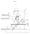
- the hologram recorder A is configured to operate in accordance with the so-called multiple angle method for performing multiple holographic recording, while also configured to be capable of reproducing holograms.
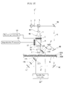
- the optical system of the recorder A includes a light source 1, a collimating lens 2, a first beam splitter 3, beam expanders 4A, 4B, a spatial light modulator 5, a second beam splitter 6, relay lenses 7A, 7B, an object lens 7, fixed mirrors 8A, 8B, 8C, a recording galvanometer mirror 9, recording condenser lenses 10A, 10B, a reproduction galvanometer mirror 11, reproduction condenser lenses 12A, 12B, and a photo detector 13. These elements are mounted on a pickup, which is not shown.
- the spatial light modulator 5 is controlled by a recording controller 20.
- the recording and the reproduction galvanometer mirrors 9, 11 are controlled by an incident angle controller 30.
- the photo detector 13 is connected with a reproduction processor 40.
- Other elements which are not illustrated include, for example, a rotation mechanism for rotating a disc-shaped hologram recording medium B, a tracking servo mechanism for moving the pickup unit in radially of the hologram recording medium B, and a microcomputer which provides overall control.
- the recording controller 20, the incident angle controller 30, and the reproduction processor 40 are connected with the microcomputer.
- the hologram recording medium B which is used in the hologram recorder A has a recording layer 91 sandwiched between two optically transparent protective layers 90A, 90B. Beams can be applied to the recording layer 91 from both sides. As a recording beam S and a reference beam R interfere with each other while crossing at a predetermined angle, holograms each having an interference stripe pattern specific to the crossing angle are recorded in the recording layer 91. For reproduction, only the reference beam R is applied as indicated by phantom lines, to the hologram recording medium B from the opposite side as was during the recording. If the beam is applied to a recorded portion of the recording layer 91, the reference beam R interferes with the recorded hologram thereby generating a diffraction beam, and the diffraction beam which serves as a reproduction beam travels to the object lens 7.
- the light source 1 which is provided by e.g. a semiconductor laser device, outputs a laser beam serving as coherent light at the time of recording and reproducing.
- the collimating lens 2 converts the laser beam from the light source 1 into a parallel beam.
- the parallel beam from the collimating lens 2 travels to the first beam splitter 3.
- the first beam splitter 3 splits the incoming parallel beam into a recording beam S which travels to the spatial light modulator 5, and a reference beam R which travels through a different optical path to the recording and the reproduction galvanometer mirrors 9, 11.
- the wavelength of the reference beam R at a time recording is always identical with the wavelength of the recording beam S.
- the beam expanders 4A, 4B provided by combined lenses, expand the diameter of the recording beam S while introducing the recording beam S to the spatial light modulator 5.
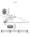
- the spatial light modulator 5 provided by e.g. a liquid crystal display device, works at the time of recording, and modulates the incoming beam into a recording beam S which represents a two-dimensional spatial modulation pattern (pixel patterns indicated by reference codes S20 through S24 in Fig. 2).
- the recording controller 20 controls the spatial light modulator 5 so that different spatial modulation patterns S20 through S24 will be generated in accordance with information to be recorded.
- the spatial modulation patterns S20 through S24 are two-dimensional pixel patterns created by conversion of data such as images and texts as an object of recording, as wall as e.g. address information.
- the address information is assigned to four ID areas A0 shown as bold-line boxes, while other information is assigned to another area than the ID area A0, i.e. a user area A1. These four ID areas A0 are signed with identical address information for the sake of redundancy, which serves to minimize error in reading address information.
- the address information includes information indicating physical position (position address information) such as a position on the track in the hologram recording medium B, as well as information indicating a page (page address information) related to a specific beam incident angle of the reference beam R.
- the page address information is expressed as a page number p-1 through p-66 as shown in Fig. 2.
- there is still another kind of information recorded by holography in the hologram recording medium B including data management information which indicates what data is recorded on each page.
- the recording beam S from the spatial light modulator 5 passes through the second beam splitter 6, the relay lenses 7A, 7B and the object lens 7, and then hits the hologram recording medium B.
- the reference beam R from the first beam splitter 3 travels via the fixed mirrors 8A, 8B to the recording galvanometer mirror 9, reflects upon the galvanometer mirror 9, passes through the condenser lenses 10A, 10B, and then hits the hologram recording medium B to interfere with the recording beam S.
- application of the recording beam S and the reference beam R is made for each unit recording region T, so as to make the beam cross each other at the unit recording region T.
- the unit recording region T as described is generally called book.
- the unit recording region T is formed sequentially along circumferential directions. It should be noted here that mutually adjacent unit recording regions T may overlap with each other within a range which will not cause crosstalk.
- the recording beam S is applied substantially perpendicularly (at zero incident angle) to the unit recording region T.
- the reference beam R is applied from diagonally above, and the incident angle of the reference beam R is variably controlled in a predetermined angular interval ⁇ by a biasing movement of the galvanometer mirror 9.
- On n represents an integer.
- the predetermined angular interval ⁇ is a constant interval.
- the angular interval ⁇ may be of inconsistent pitches.
- the incident angle of the reference beam R is aligned to a plurality of predetermined angles ⁇ 20 through ⁇ 24 which are set at a predetermined angular interval ⁇ .
- the predetermined angle ⁇ 22 serves as a reference angle.
- the predetermined angles ⁇ n including the reference angle ⁇ 22 serve as target values in controlling the incident angle of reference beam R.
- the actual amount which is controlled is the deflection angle of the galvanometer mirror 9.
- the incident angle controller 30 controls the galvanometer mirror 9 and continuously varies the incident angle of the reference beam R within a predetermined angular range ⁇ which includes the reference angle ⁇ 22 under constant application of the recording beam S and the reference beam.
- the spatial modulation pattern S22 of the recording beam S for example, is not changed.
- a hologram H22 which is made of one specific interference stripe pattern is recorded at a high density on page p-22 which is a page tuned in the reference angle ⁇ 22.
- Those pages which are tuned in the reference angle ( ⁇ 22, etc.) will be called key pages hereinafter.
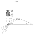
- a reference beam R' is guided via the fixed mirror 8C to the reproduction galvanometer mirror 11.
- the reproduction galvanometer mirror 11 varies the incident angle of the reference beam R' with respect to the unit recording region T at the time of reproduction.
- the galvanometer mirror 11 directs the reference beam R' toward the unit recording region T from the opposite side of the hologram recording medium B as was during the recording.
- the reference beam R' from the reproduction galvanometer mirror 11 becomes a conjugated beam whose direction is opposite to the direction at the time of recording.
- the reference beam R' passes through the condenser lenses 12A, 12B and comes to the unit recording region T.
- the spatial light modulator 5 is controlled so as not to apply the recording beam S to the unit recording region T.
- a reproduction beam P occurs in accordance with each of the holograms H20 through H24.
- the reproduction beam P travels in the opposite direction to the direction of the recording beam S, passes through the second beam splitter 6, and is received by the photo detector 13 via this second beam splitter 6 (See Fig. 1).
- the photo detector 13, which is provided by e.g. a CMOS image sensor, receives the reproduction beam P for each of the holograms H20 through H24, and detects pixel patterns P20 through P24.
- the photo detector 13 as described is capable of making a scan for each part of the ID area A0 and the user area A1 of the spatial modulation patterns S20 through S24 which were described earlier (The scanning becomes possible by using the CMOS as an imaging device in a partial scanning mode). If reproduction was made without errors, the pixel patterns P20 through P24 are identical with the earlier-described spatial modulation patterns S20 through S24 which were created at the time of recording.
- the reproduction processor 40 reproduces the information recorded in the holograms H20 through H24 based on the pixel pattern P20 through P24.
- the hologram H22 which is recorded on the key page at the reference angle ⁇ 22, has a milder curve in its diffraction efficiency with respect to angular deviation than in Fig. 5A. This means that the reproduction beam P will have an appropriate luminance even when the incident angle of the reference beam R' is slightly out of alignment at the time of reproduction, since the hologram H22 is recorded at a high density.
- the angular interval ⁇ in the variable control of the incident angle of the reference beam R at the time of recording is set to a specific value, or more specifically about 0.03 degrees. This is a value at which diffraction efficiency minimizes second time as the angular deviation gradually increases from zero degree.
- the value ⁇ which is a value when the incident angle of the reference beam R is continuously varied near the reference angle ⁇ 22 is set to a smaller vale than the angular interval ⁇ , i.e. ⁇ .
- This arrangement serves to eliminate crosstalk between the key page p-22 which is recorded at the reference angle ⁇ 22 and its adjacent user pages i.e. p-21 and p-23.
- the arrangement may be ⁇ > ⁇ , alternatively.
- the reference beam incident angle cannot be varied at an equal angular interval ⁇ , yet the arrangement offers an advantage of increased tolerance in the angular error of the reference beam when reading the key page (increased error resistance).
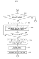
- a request for recording data for N pages comes from e.g. an unillustrated, external host computer (S1).
- the microcomputer of the hologram recorder A obtains position address information and page address information which indicate where the requested data is to be recorded, based on data management information.
- the microcomputer moves the pick up to a unit recording region T indicated by the position address information (S2).
- the incident angle controller 30 controls the deflection angle of the galvanometer mirror 9, thereby setting the incident angle of the reference beam R to an initial angle ⁇ 1 (S4). During this period, no application of the reference beam R or the recording beam S is made to the unit recording region T. Note that in the present embodiment, the initial angle ⁇ 1 is the reference angle.
- the incident angle controller 30 dynamically varies the deflection angle of the galvanometer mirror 9, thereby steplessly varies the incident angle of the reference beam R within the angular range ⁇ including the initial angle (reference angle) ⁇ 1. While the incident angle of the reference beam R is being varied, the reference beam R and the recording beam S are continuously applied to the unit recording region T. During this process, the recording beam S is modulated by the spatial light modulator 5 into a beam of spatial modulation pattern that only includes page address information n the ID areas A0. Thus, a key page tuned to the reference angle ⁇ 1 is formed in the unit recording region T by holography, and the page address information is recorded in the key page (S5).
- the recording beam of the spatial modulation pattern may also include data which is to be recorded in the user area, so that the data is recorded together with the page address information.
- a key page has a large tolerance to the angular error of the reference beam at the time of reproduction, making possible to increase user data protection by storing prioritized data (such as index files in file systems, information added to data for redundancy, etc.) in the key page.
- the incident angle controller 30 varies the deflection angle of the galvanometer mirror 9 by a predetermined angle, thereby shifting the incident angle of the reference beam R by a predetermined angular interval ⁇ (S6). Specifically, the incident angle of the reference beam R is now set to the predetermined angle ⁇ .
- the reference beam R is maintained at the predetermined angle ⁇ 2
- the reference beam R and the recording beam S are applied.
- the recording beam S is modulated by the spatial light modulator 5 into a beam of spatial modulation pattern that includes page address information in the ID areas A0, and a page of data as an object of recording in the user area A1.
- a user page tuned to the predetermined angle ⁇ 2 is formed in the unit recording region T by holography, with the page address information and a page of data recorded in the user page (S7).
- the microcomputer Upon completion of recording the data for the N pages (S8: YES), the microcomputer checks if the next page is supposed to be a key page, based on the incident angle of the reference beam R from the data management information, etc (S9).
- next page is a key page (S9: YES)
- the microcomputer has the incident angle controller 30 perform the same routine as in S4 and S5, thereby setting the incident angle of the reference beam R to the next reference angle ⁇ 22, and records page address information in the next key page (S10). Thereafter, the microcomputer finishes the series of recording procedures.
- S9 finds that the next page is a user page (S9: NO)
- the microcomputer finishes the recording procedures, with the next user page left as a blank page.
- S8 finds that recording of the data for the N pages is not completed (S8: NO)
- the microcomputer checks if the page after the next page is supposed to be a key page, based on data management information, etc. (S11).
- S11 finds that the page is a user page (S11: NO)
- the microcomputer brings the process back to S6. Specifically, the incident angle of the reference beam R is shifted by the predetermined angular interval ⁇ , and page address information and a page of data are recorded in the next user page.
- the microcomputer makes the system perform the same routine as S10, thereby recording the page address information in the next key page (S12).
- the microcomputer checks if there is any user page available for recording in the current unit recording region T, based on data management information, etc. (S13) .
- the microcomputer brings the process back to S6.
- the incident angle of the reference beam R is shifted by the predetermined angular interval ⁇ , and page address information and a page of data are recorded in the next user page.
- the microcomputer moves the pick up to the next unit recording region T based on the position address information (S14), and then brings the process back to S4.
- the data is recorded over a plurality of unit recording regions T.
- the incident angle controller 30 controls the deflection angle of the galvanometer mirror 9, thereby setting the incident angle of the reference beam R to a predetermined angle that is tuned in a blank user page (S15), and then the process goes to S7.
- S3 finds that data is already recorded in some user pages in the current unit recording region T, based on the data management information (S3: YES)
- the incident angle controller 30 controls the deflection angle of the galvanometer mirror 9, thereby setting the incident angle of the reference beam R to a predetermined angle that is tuned in a blank user page (S15), and then the process goes to S7.
- a data reproduction request comes from an external host computer.
- the microcomputer of the hologram recorder A obtains position address information and page address information of the requested data, based on data management information. Then, the microcomputer sets a scan area of the photo detector 13 trained upon the ID areas A0 (S20).
- the microcomputer moves the pick up to a unit recording region T indicated by the position address information (S21).
- the microcomputer calculates the number m of key pages which exist between the head page and the first page for the reply in the current unit recording region T based on the page address information on the basis of data management information (S22).
- the incident angle controller 30 controls the deflection angle of the galvanometer mirror 11, thereby setting the incident angle of the reference beam R' to an initial angle ⁇ 1- ⁇ (S23).
- the reference beam R' is not yet applied to the unit recording region T.
- the incident angle of the reference beam R' is not set exactly to the initial angle ⁇ 1 but to ⁇ 1- ⁇ : This is to compensate for a certain amount of error in the incident angle off the original setting at the time of recording which is anticipated from shrinkage of the medium when the laser beam is applied, wavelength variation, tilt of the medium, setting variation of the deflection angle of the galvanometer mirror 11, etc.
- the reference beam R' is applied to the unit recording region T.
- the incident angle controller 30 varies the galvanometer mirror 11 steplessly at a high speed sp1.
- a reproduction beam P of a sufficient luminance tuned in the key page occurs in the unit recording region T as described earlier with reference to Fig. 5B if an alignment is achieved between the incident angle of the reference beam R' and the reference angle used at the time of recording within a certain tolerance range.
- the photo detector 13 receives the reproduction beam P which is tuned in the key page, in the scan area which is trained upon the ID areas A0, and based on the beam reception signal from the photo detector 13, the reproduction processor 40 detects the key page (S24).
- the microcomputer keeps the reference beam R' applied on the unit recording region T whereas the incident angle controller 30 operates the galvanometer mirror 11 at a middle speed sp2, down from the high speed sp1.
- the photo detector 13 receives a reproduction beam P which is tuned in the user page; and since the reproduction beam is received by a part of scan area which is trained upon the ID areas A0, the obtained reproduction beam has a sufficient luminance.
- the reproduction processor 40 reads page address information from the ID areas A0 based on the beam reception signal from the photo detector 13 (S26).
- the microcomputer sets the scan area of the photo detector 13 to train upon the ID areas A0 and the user area A1 (S28).
- the microcomputer causes the incident angle controller 30 to correct the deflection angle of the galvanometer mirror 11 (S29). Specifically, this means that a correction value is obtained as a difference between the deflection angle of the galvanometer mirror 9 at the time of recording and the current deflection angle of the galvanometer mirror 11, and that an deflection angle of the galvanometer mirror 11 at which the amount of beam reception becomes largest is obtained based on this correction value.
- the photo detector 13 receives a reproduction beam P tuned in the user page, and outputs a corresponding beam reception signal.
- the reproduction processor 40 can reliably reproduction the data recorded in the user area A1, based on the beam reception signal from the photo detector 13 (S30).
- the microcomputer checks if the currently accessed user page is the last page to be reproduced, based on the obtained page address information (S31). If the current page is the last user page (S31: YES), the microcomputer finishes the sequence of reproduction process.
- S31 finds there is a remaining user page(s) to be reproduced (S31: NO)
- the microcomputer checks if the current user page is the last user page in the current unit recording region T (S32).
- the microcomputer sets the scan area of the photo detector 13 again to the ID areas A0 (S33).
- the incident angle controller 30 operates the galvanometer mirror 11 at a middle speed sp2 so that the incident angle of the reference beam R' will shift by a predetermined interval ⁇ .
- the reference beam R' is applied again to the unit recording region T.
- the photo detector 13 receives a reproduction beam P which is tuned in the user page, with a part of its scan area trained upon the ID areas A0, and the reproduction processor 40 reads the page address information from the ID areas A0 based on the beam reception signal from the photo detector 13 (S34).
- the microcomputer makes fine tuning of the deflection angle for maximum amount of beam reception in the scan area trained upon the ID area A0 of the photo detector 13 while operating the galvanometer mirror 11 at a low speed sp3 (S36) .
- S36 low speed sp3
- a reproduction beam P tuned in the user page and thus having a sufficient luminance cannot be obtained during this process unless the incident angle of the reference beam R' is exactly equal to the predetermined angle used at the time of recording.
- the operation speed of the galvanometer mirror 11 is the slowest sp3, it is possible to make an exact tuning by making fine adjustments on the incident angle of the reference beam R'.
- the microcomputer trains the scan area of the photo detector 13 again upon the ID areas A0 and the user area A1 (S37).
- the photo detector 13 efficiently receives the reproduction beam P which is tuned in the user page, and outputs equivalent beam reception signal.
- the reproduction processor 40 can accurately reproduction the data recorded in the user area A1, based on the beam reception signal from the photo detector 13 (S38). Thereafter,the microcomputer brings the process back to S31.
- S35 finds that the currently accessed user page is not a user page to be reproduced next (S35: NO), the microcomputer brings the process back to S34, to repeat the sequence of procedures.
- S27 finds that the currently accessed user page is not the first page to be reproduced (S27: NO), the microcomputer brings the process back to S26.
- the hologram recorder A provided by the present embodiment, it is possible to read target record data accurately and quickly at the time of reproduction, and by lowering reproduction conditions, it is also possible to offer such an advantage as increased reproduction speed.
- the hologram recorder A conducts variable control of the reference beam incident angle in order to achieve multiple recording.
- optical methods of making multiple recording under the same optical principle as varying the incident angle.
- Such methods include variable control of a laser beam wavelength, and variable control of a speckle size after the reference beam is converted into a speckle beam (in other words, "speckle-modulated").
- speckle-modulated variable control of a laser beam wavelength
- speckle-modulated variable control of a speckle size after the reference beam is converted into a speckle beam
- Fig. 9 and Fig. 10 show these other embodiments of the hologram recorder according to the present invention. Note that in describing these embodiments, those components which are the same as or similar to those in the previous embodiment will be indicated by the same reference codes, and description will be made only on differences.
- a hologram recorder A' in Fig. 9 is configured for multiple recording through variable control of laser beam wavelength, and includes a beam wavelength controller 30'. Specifically, the beam wavelength of the laser beam which comes from a light source 1 is variably controlled by the beam wavelength controller 30'. Note that the embodiment described earlier includes galvanometer mirrors 9, 11 for variable control of the incident angles of reference beams R, R'; however, in the hologram recorder A' according to the present embodiment, these will be replaced by fixed mirrors 9', 11'.
- Diffraction efficiency in user page is expressed by a curve similar to the one in Fig. 5A, with the horizontal axis representing the wavelength deviation. Therefore, by utilizing the same reproduction procedures for reproduction process as in the embodiment described earlier, it becomes possible to achieve increase in reproduction speed.
- Fig. 10 shows a hologram recorder A" in which the reference beams R, R' are converted into speckle beams and their speckle size is variably controlled for multiple recording.
- the recorder includes a speckle size controller 30". Specifically, the reference beams R, R' from the fixed mirrors 9', 11' are converted by the diffuser plates 10C, 12C into speckle beams, and these reference beams R, R' in the form of speckle beams are applied to the unit recording region T via liquid crystal filters 10D, 12D and object lenses 10E, 12E.
- the speckle size is dependent upon the numerical aperture of the object lenses 10E, 12E.
- the speckle size controller 30" can control the speckle size.
- Diffraction efficiency in user pages is expressed by a curve similar to the one in Fig. 5A, with the horizontal axis representing the dimensional deviation of the speckle size. Therefore, by utilizing the same reproduction procedures for reproduction process as in the embodiment described earlier, it becomes possible to achieve increase in reproduction speed.
Landscapes
- Physics & Mathematics (AREA)
- Optics & Photonics (AREA)
- General Physics & Mathematics (AREA)
- Optical Recording Or Reproduction (AREA)
- Holo Graphy (AREA)
- Optical Head (AREA)
Applications Claiming Priority (1)
| Application Number | Priority Date | Filing Date | Title |
|---|---|---|---|
| JP2006059118A JP2007240581A (ja) | 2006-03-06 | 2006-03-06 | ホログラム記録装置 |
Publications (2)
| Publication Number | Publication Date |
|---|---|
| EP1833048A1 true EP1833048A1 (de) | 2007-09-12 |
| EP1833048B1 EP1833048B1 (de) | 2010-04-28 |
Family
ID=38222604
Family Applications (1)
| Application Number | Title | Priority Date | Filing Date |
|---|---|---|---|
| EP07103426A Not-in-force EP1833048B1 (de) | 2006-03-06 | 2007-03-02 | Hologrammaufzeichnungsgerät und Hologrammaufzeichnungsverfahren |
Country Status (7)
| Country | Link |
|---|---|
| US (1) | US20070206255A1 (de) |
| EP (1) | EP1833048B1 (de) |
| JP (1) | JP2007240581A (de) |
| KR (1) | KR100831859B1 (de) |
| CN (1) | CN101034280A (de) |
| DE (1) | DE602007006086D1 (de) |
| TW (1) | TW200739290A (de) |
Families Citing this family (22)
| Publication number | Priority date | Publication date | Assignee | Title |
|---|---|---|---|---|
| JP4974960B2 (ja) * | 2008-04-28 | 2012-07-11 | 日本放送協会 | 角度多重ホログラム記録角度特定方法 |
| WO2010029608A1 (ja) * | 2008-09-09 | 2010-03-18 | パイオニア株式会社 | ホログラム装置及び記録方法 |
| WO2010029613A1 (ja) * | 2008-09-09 | 2010-03-18 | パイオニア株式会社 | ホログラム装置及び記録方法 |
| JP5104695B2 (ja) * | 2008-09-29 | 2012-12-19 | 株式会社日立製作所 | 情報記録装置 |
| JP2010225243A (ja) * | 2009-03-24 | 2010-10-07 | Toshiba Corp | 光情報記録方法および装置 |
| WO2011081107A1 (ja) * | 2009-12-28 | 2011-07-07 | 日本電気株式会社 | 光学的情報処理装置及び光学的情報処理方法 |
| JP5183667B2 (ja) * | 2010-04-21 | 2013-04-17 | 日立コンシューマエレクトロニクス株式会社 | 再生装置および再生方法 |
| JP5581111B2 (ja) * | 2010-05-12 | 2014-08-27 | 日立コンシューマエレクトロニクス株式会社 | 光情報再生装置および光情報再生方法 |
| JP5358530B2 (ja) * | 2010-07-28 | 2013-12-04 | 日立コンシューマエレクトロニクス株式会社 | 光情報記録再生装置及び再生装置 |
| JP5753767B2 (ja) | 2011-11-18 | 2015-07-22 | 日立コンシューマエレクトロニクス株式会社 | 光情報記録再生装置、光情報記録再生方法、光情報記録媒体 |
| JP2012133879A (ja) * | 2012-01-06 | 2012-07-12 | Hitachi Ltd | 情報記録装置、情報再生装置および記録媒体 |
| EP2650655B1 (de) * | 2012-04-12 | 2014-09-03 | Siemens Aktiengesellschaft | Messwertgeber zum Erhalt einer Positionsinformation |
| US20150364151A1 (en) * | 2012-04-23 | 2015-12-17 | Toshiki Ishii | Optical information recording and reproducing device, optical information recording and reproducing method, and reproducing device |
| JP2015082327A (ja) * | 2013-10-21 | 2015-04-27 | 株式会社日立エルジーデータストレージ | 光情報再生装置、光情報再生方法および光情報記録方法 |
| WO2016017023A1 (ja) * | 2014-08-01 | 2016-02-04 | 日立コンシューマエレクトロニクス株式会社 | 記録再生方法および記録再生装置 |
| KR102755294B1 (ko) * | 2017-01-17 | 2025-01-17 | 삼성전자주식회사 | 영상을 표시하는 방법, 장치 및 기록매체 |
| DE102019109437A1 (de) * | 2019-04-10 | 2020-10-15 | HELLA GmbH & Co. KGaA | Verfahren und Vorrichtung zur Herstellung eines computergenerierten Hologramms, Hologramm sowie Beleuchtungsvorrichtung für ein Fahrzeug |
| EP3886092A1 (de) | 2020-03-26 | 2021-09-29 | Microsoft Technology Licensing, LLC | Holographische speicherung |
| EP3886091A1 (de) | 2020-03-26 | 2021-09-29 | Microsoft Technology Licensing, LLC | Holografischer speicher |
| EP3886093A1 (de) | 2020-03-26 | 2021-09-29 | Microsoft Technology Licensing, LLC | Optische datenübertragung |
| EP3885646A1 (de) | 2020-03-26 | 2021-09-29 | Microsoft Technology Licensing, LLC | Wellenleiternetzwerk |
| WO2023117211A1 (en) * | 2021-12-22 | 2023-06-29 | Ams International Ag | Hologram recording system and method |
Citations (4)
| Publication number | Priority date | Publication date | Assignee | Title |
|---|---|---|---|---|
| EP0817201A2 (de) * | 1996-06-26 | 1998-01-07 | Lucent Technologies Inc. | Verfahren, Gerät und Medium für ein holographisches Datenspeichersystem |
| WO2004112045A2 (en) * | 2003-06-07 | 2004-12-23 | Aprilis, Inc. | High areal density holographic data storage system |
| JP2005031395A (ja) * | 2003-07-14 | 2005-02-03 | Tdk Corp | ホログラフィック記録媒体、ホログラフィック記録媒体へのアドレス情報付加方法及びアドレス方法 |
| US20060007512A1 (en) * | 2004-07-07 | 2006-01-12 | Sony Corporation | Hologram recording apparatus and hologram recording method |
Family Cites Families (11)
| Publication number | Priority date | Publication date | Assignee | Title |
|---|---|---|---|---|
| JP4108661B2 (ja) * | 1998-02-27 | 2008-06-25 | 株式会社オプトウエア | 光情報記録方法及び光情報再生方法 |
| US6958967B2 (en) * | 2000-11-17 | 2005-10-25 | Matsushita Electric Industrial Co., Ltd. | Holographic optical information recording/reproducing device |
| JP3844460B2 (ja) * | 2002-08-05 | 2006-11-15 | パイオニア株式会社 | 空間光変調器 |
| JP4449384B2 (ja) * | 2003-09-24 | 2010-04-14 | Tdk株式会社 | ホログラフィック記録装置 |
| JP4610976B2 (ja) * | 2004-03-12 | 2011-01-12 | 三星電子株式会社 | ホログラムメモリ媒体および記録装置、再生装置 |
| JP4355607B2 (ja) * | 2004-04-15 | 2009-11-04 | Tdk株式会社 | ホログラフィック記録方法、ホログラフィック記録装置、ホログラフィック記録再生方法、ホログラフィック記録再生装置及びホログラフィック記録媒体 |
| JP2005310308A (ja) * | 2004-04-23 | 2005-11-04 | Sony Corp | ホログラム記録再生装置及びホログラム記録再生方法 |
| JP2005332520A (ja) * | 2004-05-21 | 2005-12-02 | Alps Electric Co Ltd | ホログラム装置 |
| JP4459721B2 (ja) * | 2004-06-01 | 2010-04-28 | アルプス電気株式会社 | ホログラム記録媒体及びその書込み方法 |
| JP2006154163A (ja) | 2004-11-29 | 2006-06-15 | Sony Corp | ホログラム記録装置、ホログラム再生装置、ホログラム記録方法及びホログラム再生方法 |
| US7589877B2 (en) * | 2005-12-02 | 2009-09-15 | Inphase Technologies, Inc. | Short stack recording in holographic memory systems |
-
2006
- 2006-03-06 JP JP2006059118A patent/JP2007240581A/ja active Pending
-
2007
- 2007-02-28 KR KR1020070020050A patent/KR100831859B1/ko not_active Expired - Fee Related
- 2007-03-02 TW TW096107175A patent/TW200739290A/zh unknown
- 2007-03-02 DE DE602007006086T patent/DE602007006086D1/de active Active
- 2007-03-02 EP EP07103426A patent/EP1833048B1/de not_active Not-in-force
- 2007-03-05 US US11/713,842 patent/US20070206255A1/en not_active Abandoned
- 2007-03-06 CN CNA2007100867134A patent/CN101034280A/zh active Pending
Patent Citations (5)
| Publication number | Priority date | Publication date | Assignee | Title |
|---|---|---|---|---|
| EP0817201A2 (de) * | 1996-06-26 | 1998-01-07 | Lucent Technologies Inc. | Verfahren, Gerät und Medium für ein holographisches Datenspeichersystem |
| WO2004112045A2 (en) * | 2003-06-07 | 2004-12-23 | Aprilis, Inc. | High areal density holographic data storage system |
| JP2005031395A (ja) * | 2003-07-14 | 2005-02-03 | Tdk Corp | ホログラフィック記録媒体、ホログラフィック記録媒体へのアドレス情報付加方法及びアドレス方法 |
| US20070008598A1 (en) * | 2003-07-14 | 2007-01-11 | Tdk Corporation | Holographic recording medium, method for adding address information to holographic recording medium, and method of addressing |
| US20060007512A1 (en) * | 2004-07-07 | 2006-01-12 | Sony Corporation | Hologram recording apparatus and hologram recording method |
Also Published As
| Publication number | Publication date |
|---|---|
| EP1833048B1 (de) | 2010-04-28 |
| JP2007240581A (ja) | 2007-09-20 |
| TW200739290A (en) | 2007-10-16 |
| DE602007006086D1 (de) | 2010-06-10 |
| US20070206255A1 (en) | 2007-09-06 |
| KR20070091537A (ko) | 2007-09-11 |
| KR100831859B1 (ko) | 2008-05-22 |
| CN101034280A (zh) | 2007-09-12 |
Similar Documents
| Publication | Publication Date | Title |
|---|---|---|
| EP1833048B1 (de) | Hologrammaufzeichnungsgerät und Hologrammaufzeichnungsverfahren | |
| US8004950B2 (en) | Optical pickup, optical information recording and reproducing apparatus and method for optically recording and reproducing information | |
| WO2004102541A1 (en) | High data density volumetric holographic data storage method and system | |
| US8270278B2 (en) | Optical recording apparatus, optical recording method, recording medium, and reproducing method | |
| US7990830B2 (en) | Optical pickup, optical information recording apparatus and optical information recording and reproducing apparatus using the optical pickup | |
| US8787136B2 (en) | Holographic memory apparatus and method for adjusting incident angle of reference beam | |
| JP2009048002A (ja) | ホログラム再生装置およびホログラム記録再生装置 | |
| EP1843334B1 (de) | Optisches Informationswiedergabegerät und optisches Informationswiedergabeverfahren damit | |
| US20100128591A1 (en) | Optical information reproducing apparatus, optical information recording and reproducing apparatus | |
| JP2007240820A (ja) | ホログラム記録再生装置 | |
| JPH1152827A (ja) | 3次元ホログラフィックデータ格納システム | |
| US20090016189A1 (en) | Recording/reproducing apparatus, method of reproducing data, and servo controlling method | |
| KR20080112570A (ko) | 홀로그래픽 기록/재생 장치 | |
| EP2194529B1 (de) | Vorrichtung und verfahren zur aufzeichnung/wiedergabe optischer informationen und zum datenabruf durch bezug auf ein medium zur aufzeichnung optischer informationen | |
| US20060164705A1 (en) | Hologram system | |
| EP1850336B1 (de) | Optisches Informationswiedergabegerät und optisches Informationsaufzeichnungsgerät unter Verwendung von Holografie | |
| JP6894110B2 (ja) | ホログラム記録再生装置 | |
| WO2010029608A1 (ja) | ホログラム装置及び記録方法 | |
| JP6662521B2 (ja) | ホログラム記録再生装置およびホログラム記録再生方法 | |
| JP2008299992A (ja) | ホログラフィックメモリ記録装置、ホログラフィック再生装置、又はホログラフィック記録再生装置 | |
| WO2010029613A1 (ja) | ホログラム装置及び記録方法 | |
| EP1890285A1 (de) | Verfahren zur Servosteuerung in einem holografischen Speichersystem | |
| JP2012138148A (ja) | 情報記録再生装置および情報記録再生方法 | |
| JP2017147010A (ja) | 光情報記録再生装置、ホログラム記録再生方法 |
Legal Events
| Date | Code | Title | Description |
|---|---|---|---|
| PUAI | Public reference made under article 153(3) epc to a published international application that has entered the european phase |
Free format text: ORIGINAL CODE: 0009012 |
|
| AK | Designated contracting states |
Kind code of ref document: A1 Designated state(s): AT BE BG CH CY CZ DE DK EE ES FI FR GB GR HU IE IS IT LI LT LU LV MC MT NL PL PT RO SE SI SK TR |
|
| AX | Request for extension of the european patent |
Extension state: AL BA HR MK YU |
|
| 17P | Request for examination filed |
Effective date: 20080311 |
|
| 17Q | First examination report despatched |
Effective date: 20080411 |
|
| AKX | Designation fees paid |
Designated state(s): DE FR GB |
|
| RTI1 | Title (correction) |
Free format text: HOLOGRAM RECORDER AND HOLOGRAM RECORDING METHOD |
|
| GRAP | Despatch of communication of intention to grant a patent |
Free format text: ORIGINAL CODE: EPIDOSNIGR1 |
|
| GRAS | Grant fee paid |
Free format text: ORIGINAL CODE: EPIDOSNIGR3 |
|
| GRAA | (expected) grant |
Free format text: ORIGINAL CODE: 0009210 |
|
| AK | Designated contracting states |
Kind code of ref document: B1 Designated state(s): DE FR GB |
|
| REG | Reference to a national code |
Ref country code: GB Ref legal event code: FG4D |
|
| REF | Corresponds to: |
Ref document number: 602007006086 Country of ref document: DE Date of ref document: 20100610 Kind code of ref document: P |
|
| PLBE | No opposition filed within time limit |
Free format text: ORIGINAL CODE: 0009261 |
|
| STAA | Information on the status of an ep patent application or granted ep patent |
Free format text: STATUS: NO OPPOSITION FILED WITHIN TIME LIMIT |
|
| 26N | No opposition filed |
Effective date: 20110131 |
|
| PGFP | Annual fee paid to national office [announced via postgrant information from national office to epo] |
Ref country code: FR Payment date: 20110216 Year of fee payment: 5 |
|
| PGFP | Annual fee paid to national office [announced via postgrant information from national office to epo] |
Ref country code: DE Payment date: 20120103 Year of fee payment: 6 |
|
| PGFP | Annual fee paid to national office [announced via postgrant information from national office to epo] |
Ref country code: GB Payment date: 20120104 Year of fee payment: 6 |
|
| REG | Reference to a national code |
Ref country code: FR Ref legal event code: ST Effective date: 20121130 |
|
| PG25 | Lapsed in a contracting state [announced via postgrant information from national office to epo] |
Ref country code: FR Free format text: LAPSE BECAUSE OF NON-PAYMENT OF DUE FEES Effective date: 20120402 |
|
| GBPC | Gb: european patent ceased through non-payment of renewal fee |
Effective date: 20130302 |
|
| REG | Reference to a national code |
Ref country code: DE Ref legal event code: R119 Ref document number: 602007006086 Country of ref document: DE Effective date: 20131001 |
|
| PG25 | Lapsed in a contracting state [announced via postgrant information from national office to epo] |
Ref country code: DE Free format text: LAPSE BECAUSE OF NON-PAYMENT OF DUE FEES Effective date: 20131001 Ref country code: GB Free format text: LAPSE BECAUSE OF NON-PAYMENT OF DUE FEES Effective date: 20130302 |