EP1833060B1 - Grille d'espacement munie d'ailettes de mélange et assemblage de combustible nucléaire comportant une telle grille d'espacement - Google Patents
Grille d'espacement munie d'ailettes de mélange et assemblage de combustible nucléaire comportant une telle grille d'espacement Download PDFInfo
- Publication number
- EP1833060B1 EP1833060B1 EP07004872A EP07004872A EP1833060B1 EP 1833060 B1 EP1833060 B1 EP 1833060B1 EP 07004872 A EP07004872 A EP 07004872A EP 07004872 A EP07004872 A EP 07004872A EP 1833060 B1 EP1833060 B1 EP 1833060B1
- Authority
- EP
- European Patent Office
- Prior art keywords
- grid
- spacer grid
- mixing
- fuel rods
- piece
- Prior art date
- Legal status (The legal status is an assumption and is not a legal conclusion. Google has not performed a legal analysis and makes no representation as to the accuracy of the status listed.)
- Expired - Fee Related
Links
Images


Classifications
-
- G—PHYSICS
- G21—NUCLEAR PHYSICS; NUCLEAR ENGINEERING
- G21C—NUCLEAR REACTORS
- G21C3/00—Reactor fuel elements and their assemblies; Selection of substances for use as reactor fuel elements
- G21C3/30—Assemblies of a number of fuel elements in the form of a rigid unit
- G21C3/32—Bundles of parallel pin-, rod-, or tube-shaped fuel elements
- G21C3/322—Means to influence the coolant flow through or around the bundles
-
- G—PHYSICS
- G21—NUCLEAR PHYSICS; NUCLEAR ENGINEERING
- G21C—NUCLEAR REACTORS
- G21C3/00—Reactor fuel elements and their assemblies; Selection of substances for use as reactor fuel elements
- G21C3/30—Assemblies of a number of fuel elements in the form of a rigid unit
- G21C3/32—Bundles of parallel pin-, rod-, or tube-shaped fuel elements
- G21C3/34—Spacer grids
- G21C3/352—Spacer grids formed of assembled intersecting strips
-
- Y—GENERAL TAGGING OF NEW TECHNOLOGICAL DEVELOPMENTS; GENERAL TAGGING OF CROSS-SECTIONAL TECHNOLOGIES SPANNING OVER SEVERAL SECTIONS OF THE IPC; TECHNICAL SUBJECTS COVERED BY FORMER USPC CROSS-REFERENCE ART COLLECTIONS [XRACs] AND DIGESTS
- Y02—TECHNOLOGIES OR APPLICATIONS FOR MITIGATION OR ADAPTATION AGAINST CLIMATE CHANGE
- Y02E—REDUCTION OF GREENHOUSE GAS [GHG] EMISSIONS, RELATED TO ENERGY GENERATION, TRANSMISSION OR DISTRIBUTION
- Y02E30/00—Energy generation of nuclear origin
- Y02E30/30—Nuclear fission reactors
Definitions
- the present invention relates generally to nuclear reactors and, more particularly, to spacer grids for a nuclear fuel assembly, including mixing vanes to effectively mix coolant as it flows through the fuel assembly.
- Nuclear fuel assemblies for light water nuclear reactors such as, for example, pressurized water reactors (PWRs) and boiling water reactors (BWRs), generally include a plurality of fuel rods with circular cross-sections that are arranged parallel to one another at regularly or irregularly spaced intervals.
- Each fuel rod comprises a stack of fuel pellets (e.g., uranium oxide pellets) surrounded with cladding that is made from zirconium alloy or other suitable material.
- the fuel rods are held at the spaced intervals with respect to one another by one or more spacer grids.
- Each spacer grid includes a plurality of interlocking grid straps that are welded together to form an array of four-walled cells in an "egg-crate" configuration.
- a fuel rod may be contained within each of the four-walled cells.
- the entire fuel assembly typically has a square cross-section with a 14x14, 15x15, 16x16, or 17x17 array of fuel rods.
- One or more outer straps may encircle the periphery of each spacer grid.
- FIG 1 presents a partial perspective view of a conventional spacer grid 100 for a fuel assembly 102.
- the spacer grid 100 includes two sets of perpendicularly placed grid straps 112, 114.
- Each grid strap 112, 114 includes a series of regularly spaced notches (not shown) that allow for the assembly and interlocking of the grid straps 112, 114 to form an array of four-walled cells 116.
- Each four-walled cell 116 contains four intersections 118.
- the grid straps 112, 114 may be welded together at these intersections 118.
- the purpose of the four-walled cell 116 is to support a single fuel rod 130 ( Figure 2 ) in the square array of the fuel assembly 102.
- the periphery of the grid straps 112, 114 may be encircled with one or more outer straps 120.
- a plurality of springs 122 and a plurality of dimples 124 are integrally formed on, or attached to, the grid straps 112, 114 and extend inwardly within each four-walled cell 116.
- the springs 122 and dimples 124 provide support structures for contacting the fuel rod cladding and holding it within the four-walled cell 116.
- Figure 2 presents a cross-sectional top plan view of one of the aforementioned four-walled cells 116, with a fuel rod 130 contained therein. As shown, the springs 122 and dimples 124 extend inwardly within the four-walled cell 116 to engage and provide support for the fuel rod 130, as previously discussed.
- a coolant such as for example, water
- the temperature of the coolant varies as it travels upwards, absorbing thermal energy from the fuel rods.
- the coolant may be partially overheated, which can adversely affect the thermal performance of the fuel assembly and reduce the output power of the fuel rods.
- One way of alleviating these partially overheated regions is to design the spacer grids to more effectively deflect and mix the coolant as it flows upwards through the fuel assembly, thereby promoting a more uniform distribution of coolant temperature.
- Such a design can be accomplished by attaching "mixing vanes" to the top, downstream portion of the grid straps that comprise the spacer grid, as shown.
- the mixing vanes are intended to promote the flow of coolant in a lateral direction as well as a longitudinal direction along the fuel rod axes. This flow pattern allows the coolant to more effectively move between the fuel rods, and between the lower temperature regions and the partially overheated regions of the fuel assembly.
- Figure 3 presents a partial perspective view of a grid strap 140 and conventional PWR mixing vane 142, wherein the mixing vane 142 is disposed at the top, downstream portion of a cell wall 144.
- BWR vanes are typically much smaller in size.
- Other conventional mixing vane designs are disclosed in U.S. Patent No. 5,440,599 to Rodack et al. , U.S. Patent No. 6,807,246 to Kim et al. , U.S. Patent No. 3,862,000 to Pugh et al. , U.S. Patent No. 4, 758,403 to Noailly , U.S. Patent No.
- the pre-characterizing portion of claim 1 is based on prior art document EP 0 468 871 A1 .
- the present invention provides a spacer grid for a nuclear fuel assembly having a plurality of elongated fuel rods.
- the spacer grid employs novel mixing vanes which include an upper piece and a lower piece, which are connected to a middle ligament that is coupled to the top or downstream portion of a grid strap forming the spacer grid.
- each four-walled cell of the spacer grid may contain four mixing vanes - one positioned at the top, downstream portion of each wall.
- the upper piece, lower piece, and middle ligament may be bent, rotated, and/or twisted into various positions to more effectively mix the coolant and affect the coolant's flow as it moves upwards through the fuel assembly.
- the mixing vane has an "S" shape when viewed from an end elevational vantage point. More specifically, the middle ligament is positioned parallel to the longitudinal axes of the fuel rods, the upper piece is bent towards the fuel rod, and the lower piece is bent away from the fuel rod, thereby defining the general S-shape. In another preferred embodiment, the mixing vane has a parabolic shape when viewed from the end elevational vantage point. A nuclear fuel assembly employing such mixing vanes, is also disclosed.
- An object of the present invention is to provide a mixing vane that is tunable in order to affect ( i.e ., control or adjust) and thus optimize for the particular application at hand the coolant flow pattern that is formed, rather than merely deflecting the coolant flow.
- Another object of the present invention is to provide a mixing vane that promotes optimized even and sustained interchannel mixing.
- Yet another object of the present invention is to provide a mixing vane that more effectively mixes coolant as it moves upwards through the fuel assembly, thereby mitigating regions of varying coolant temperature.
- a further object of the present invention is to provide mixing vane that is easily manufactured using conventional die technology.
- Another object of the present invention is to provide a mixing vane with an upper piece, a lower piece, and a middle ligament, that are easily tuned or adjusted by bending, rotating, and twisting, in order to optimize the coolant flow.
- Figure 1 is a partial perspective view of a conventional spacer grid for use with a fuel assembly having a square cross-section.
- Figure 2 is a cross-sectional view of a four-walled cell and fuel rod located within a conventional spacer grid.
- Figure 3 is a partial perspective view of a grid strap and conventional mixing vane.
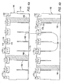
- Figures 4a and 4b are partial elevational views of two types of perpendicularly positioned, interlocking grid straps in accordance with a preferred embodiment of the present invention.
- Figure 5 is an elevational view of a portion of one grid strip which defines a single cell wall, and mixing vane that has been bent in accordance with a preferred embodiment of the present invention.
- Figures 6a and 6b are partial perspective and top plan views, respectively, of a grid strap intersection of a spacer grid in accordance with a preferred embodiment of the present invention.
- Figure 7 is a partial perspective view of a portion of a spacer grid and a single four-walled cell thereof in accordance with a preferred embodiment of the present invention.
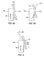
- FIGS 8a and 8b are schematic views of an S-shaped mixing vane with various bend angles in accordance with preferred embodiments of the present invention.
- Figure 9 is a schematic view of an S-shaped mixing vane that has been rotated in accordance with preferred embodiments of the present invention.
- Figures 10a and 10b are schematic views of S-shaped mixing vanes that have been twisted in accordance with preferred embodiments of the present invention.
- each mixing vane is contemplated as being formed from the grid strap material and connected to the grid strap as an integral component, that the mixing vanes could also be connected by welding, brazing, or mechanically securing them to the grid straps.
- the mixing vanes can also be made from any known or suitable material (e.g. , without limitation zirconium alloy or nickel-steel alloy).
- the terms “bend” and “bend angle” are used when referring to a bend in the upper or lower piece of the mixing vane.
- the terms “rotate” and “rotation angle” are used when referring to a rotation of the middle ligament.
- the terms “twist” and “degree of twist” are used when referring to a twist of the upper piece, lower piece, or middle ligament.
- FIGs 4a, 4b , 5, 6a , 6b and 7 illustrate a preferred embodiment of the present invention in which the grid straps of a spacer grid include generally S-shaped mixing vanes. While the present invention is not limited to any particular number of mixing vanes, four mixing vanes are positioned around each fuel rod and four-walled cell in the preferred embodiment (best shown in Figure 7 ).
- FIGs 4a and 4b are partial elevational views of two types of perpendicularly positioned, interlocking grid straps 160, 162.
- a plurality of these grid straps 160, 162 are placed perpendicular to each other and connected together such that the downwardly positioned notches 166 on the first type of grid strap 160, shown in Figure 4a , engage the upwardly positioned notches 168 on the second type of grid strap 162, shown in Figure 4b .
- the location where the notches 166, 168 are connected is known as a grid strap intersection 170 ( Figures 6a and 6b ).
- Each grid strap 160, 162 includes a plurality of mixing vanes 172, which are shown in a flattened state in the unassembled views of Figures 4a and 4b .
- Each mixing vane includes an upper piece 174 and a lower piece 176 that are connected to a middle ligament 178.
- the middle ligament 178 is connected to the grid strap 160, 162.
- each cell wall 180 two cell walls 180 are shown in cross-hatch in Figures 4a and 4b ) of each grid strap 160, 162 preferably contains a single mixing vane 172.
- the mixing vane 172 may be connected to the grid strap 160, 162 at its top or "downstream" portion 182.
- the mixing vane 172 is preferably connected to the grid strap 160, 162 so that the middle ligament extends outward from the grid strap 160,162 in a direction that is substantially orthogonal with respect to the longitudinal axis 184 of the cell wall 180.
- the grid straps 160, 162 in the examples of Figures 4a and 4b are shown without springs and dimples in the cell walls 180. It will, however, be appreciated that any suitable number and configuration of dimples and springs could be employed (see, for example, Figure 7 ).
- the mixing vanes 172 of Figures 4a and 4b are shown in a flattened position, prior to being assembled, the mixing vanes 172 are preferably bent and/or twisted into various positions to positively affect and thus optimize the flow of coolant as it moves through the fuel assembly. More specifically, the vanes 172 may be adjusted or fine tuned in order to optimize the coolant flow, as desired, for the particular application in which they are being employed.
- Figure 5 is an elevational view of a single cell wall 180 and mixing vane 172 that has been bent in accordance with a preferred embodiment of the invention.
- the upper piece 174 of the vane 172 has been bent at its connection with the middle ligament 178, and placed at a "bend angle" of approximately +45 degrees from the vertical.
- the vertical direction is defined by the longitudinal axis 184 of the cell wall 180.
- the lower piece 176 of the vane 172 has also been bent at its connection with the middle ligament 178, and placed at a "bend angle" of approximately -45 degrees from the vertical.
- the middle ligament 178 has been bent at its connection with the grid strap 160 and placed at a "rotation angle" of approximately -45 degrees with respect to the plane of the grid strap 160.
- a negative rotation angle for the middle ligament 178 indicates a counterclockwise rotation when viewed from the top of the fuel assembly, and a positive rotation angle indicates a clockwise rotation.
- the middle ligament 178 in the example shown, remains vertically aligned and parallel to the longitudinal axis 184 of the cell wall 180.
- the mixing vane 172 appears to have an S-shape when it is viewed directly from the side ( i.e., from the left end with respect to Figure 5 ).
- the grid strap 160 of Figure 5 does not show springs or dimples in cell wall 180, it will be appreciated that any suitable number and configuration of dimples and springs could be employed (see, for example, Figure 7 ).
- Figure 6a is a partial perspective view of a grid strap intersection 170 of the spacer grid
- Figure 6b is a top plan view of such intersection 170.
- the grid strap intersection 170 occurs where two grid straps 160, 162 have been perpendicularly positioned and interlocked together using their upwardly and downwardly positioned notches 166,168 ( Figures 4a and 4b ).
- each grid strap cell wall 180 contains a single mixing vane 172
- the grid strap intersection 170 is surrounded with a total of four mixing vanes 172, two per grid strap 160, 162.
- the upper piece 174 of each vane 172 has been bent at its connection with the middle ligament 178, and placed at a bend angle of approximately +45 degrees from the vertical.
- each vane 172 has been bent at its connection with the middle ligament 178, and angled approximately -45 degrees from the vertical.
- a positive angle for the upper or lower piece 174, 176 indicates that the piece has been bent away from the grid strap intersection 170, and towards an adjacent fuel rod (not shown).
- a negative angle for the upper or lower piece 174, 176 indicates that the piece has been bent towards the grid strap intersection 170, and away from an adjacent fuel rod (not shown).
- the middle ligament 178 of each vane 172 has been bent at its connection with the grid strap 160, 162, and placed at a rotation angle of approximately +30 degrees from the plane of each grid strap 160, 162.
- a positive rotation angle for the middle ligament 178 indicates a clockwise rotation when viewed from a top plan view perspective (see, for example, Figure 6b ), and a negative rotation angle indicates a counterclockwise rotation.
- FIG. 6b The top plan view of Figure 6b further shows the interaction of the mixing vanes 172 with fuel rods 210 of the fuel assembly.
- One complete fuel rod 210 shown in simplified form in phantom line drawing) and portions of the three adjacent fuel rods 210, are shown.
- FIG. 7 is a partial perspective view of a spacer grid 200 in accordance with the invention.
- the spacer grid 200 in accordance with the invention forms any known or suitable array of a plurality of four-walled cells 202, similar for example, to the spacer grid 100 shown in Figure 1 .
- Figure 7 and, in particular mixing vanes 172 are not drawn to scale.
- the four-walled cell 202 occurs where four grid straps 160, 162, 164, 165 interlock in a generally perpendicular configuration to create an opening for supporting a fuel rod 210 (shown in simplified form in phantom line drawing) therein.
- each grid strap 160, 162, 164, 165 includes a plurality of springs 186 and dimples 188 of any known or suitable orientation, for securing the fuel rod 210.
- each cell wall 180 includes a single mixing vane 172, a total of four mixing vanes 172 surround the fuel rod 210 and four-walled cell 202.
- the upper piece 174 of each vane 172 has a bend angle of approximately +45 degrees from the vertical 184. The positive angle indicates that the piece has been bent towards the fuel rod 210.
- the lower piece 176 of each vane 172 has a bend angle of approximately-45 degrees from the vertical.
- the negative angle indicates that the piece has been bent away from the fuel rod 210.
- the middle ligament 178 of each vane 172 has a rotation angle of approximately +45 degrees from the plane of each grid strap 160, 162, 164, 165, with the positive angle indicating a clockwise direction of rotation when viewed from a top plan view perspective.
- the spacer grid 200 includes a plurality of perpendicular, interlocking grid straps 160, 162, 164, 165 that define the aforementioned grid strap intersections 170 ( Figures 6a and 6b ) and the four-walled cells 202.
- each mixing vane 172 appears to have an S-shape. It is in this manner ( i.e.
- the exemplary mixing vanes 172 assist in mixing coolant to create optimized even and sustained mixing (e.g., without limitation, a strong swirl and interchannel mixing) of the coolant as it moves upwards through the fuel assembly.
- the present invention is not, however, limited to the embodiment shown hereinbefore. It will be appreciated that a wide variety of other mixing vane configurations are within the scope of the invention.
- the upper and lower pieces of the mixing vane can have any suitable positive or negative bend angle 220, 222 with respect to the vertical ( i.e. , the longitudinal axis 184 of the cell wall 180), ranging from about 0 to about +90 degrees or about 0 to about -90 degrees.
- Figure 8a is a side view of an S-shaped mixing vane 172 which shows how bend angles 220, 222 of the upper piece 174 and lower piece 176 are measured from the vertical or longitudinal axis 184 of the grid strap 160.
- Figure 8b illustrates example alternative bends 224, 226 for the upper piece 174 and lower piece 176 of the mixing vane 172 (with the alternatives shown in dashed line drawing).
- the upper piece 174 and/or lower piece 176 have bends 224, 226 ranging from about 0 to +45 degrees or about 0 to -45 degrees.
- the upper and lower pieces 174, 176 could alternatively both be bent towards an adjacent fuel rod, in order to form a parabolic-shaped mixing vane (not shown). It will also be appreciated that, rather than being bent, the upper and/or lower pieces 174, 176 could remain unbent ( i.e. , vertical at 0 degrees). It will still further be appreciated that while the upper and lower pieces 174, 176 are preferably bent at their connection with the middle ligament 178, a bend could occur at any location along the upper and lower piece 174, 176, and/or each piece 174, 176 can contain multiple bends (not shown).
- Figure 9 is a side view of an S-shaped mixing vane 172 which shows how the rotation angle 228, as previously defined herein, for the middle ligament 178 is measured from the vertical or longitudinal axis 184 of the grid strap ( i.e., 160).
- the middle ligament 178 may have any positive or negative rotation angle 228 with respect to the vertical, ranging from about 0 to +90 degrees or from about 0 to -90 degrees.
- the middle ligament 178 is rotated from about 0 to +45 degrees (towards a fuel rod) or from about 0 to -45 degrees (away from a fuel rod).
- the middle ligament 178 may remain at 0 degrees, parallel to the vertical. Additionally, while the example of Figure 9 shows a pivot point 230 that is located approximately at the center of the middle ligament 178, the pivot point may occur at any location on the middle ligament 178.
- a middle ligament 178 may also contain multiple pivot points (not shown) and therefore multiple rotation angles (not shown).
- the upper piece 174, lower piece 176, and middle ligament 178 may be "twisted" (i.e., subjected to torsion) in a clockwise or counterclockwise direction, as shown in Figures 10a and 10b.
- Figure 10a is a side view of two mixing vanes 172, wherein the upper piece 174 of each vane 172 is twisted.
- the "degree of twist” may range from about 0 to +90 degrees or from 0 to about -90 degrees (either clockwise or counterclockwise) with respect to axis 173.
- any suitable combination of twisting of one or both of the upper and lower pieces 174, 176 could be employed.
- Figure 10b is a partial perspective view of four mixing vanes 172 surrounding a grid strap intersection 170.
- the upper pieces 174 of two opposing mixing vanes 172 are twisted, while the upper pieces of the other two mixing vanes 172 are not.
- the degree of twist ranges from about 0 to +90 degrees or from about 0 to -90 degrees, in either a clockwise or counterclockwise direction.
- a single upper piece 174, lower piece 176, or middle ligament 178 may include multiple twists, and that the various mixing vanes 172 and components thereof, of a particular intersection 170 may have any suitable combination of bend, twist, and/or rotation.
- a spacer grid may contain fuel rods that are surrounded with mixing vanes and fuel rods that are not. Not every four-walled cell of a spacer grid is required to include a mixing vane.
- a fuel rod may be surrounded with anywhere from zero to four mixing vanes.
- a fuel rod is preferably surrounded with two or four mixing vanes.
- each mixing vane it is also preferable for the upper piece of each mixing vane to bend towards the fuel rod, and for the lower piece of each mixing vane to bend away from the fuel rod, although the mixing vanes in a given spacer grid may vary with respect to their bends, rotations, and twists. At least one upper piece may be twisted and/or bent with respect to the longitudinal axis of the cell walls, at least one lower piece may be twisted and/or bent with respect to the longitudinal axis of the cell walls, and/or at least one middle ligament may be twisted and/or bent with respect to a plane on which the grid strap resides.
Landscapes
- Physics & Mathematics (AREA)
- Engineering & Computer Science (AREA)
- Plasma & Fusion (AREA)
- General Engineering & Computer Science (AREA)
- High Energy & Nuclear Physics (AREA)
- Apparatus Associated With Microorganisms And Enzymes (AREA)
- Fuel Cell (AREA)
Claims (11)
- Grille d'espacement (200) pour un assemblage combustible nucléaire comprenant une pluralité de crayons de combustible allongés (210) et apte à recevoir un caloporteur s'écoulant sur les crayons de combustible (210), la grille d'espacement (200) comprenant :une pluralité de sangles de grille à enclenchement (160, 162,164,165) formant une pluralité de cellules à quatre parois (202) structurées pour supporter les crayons de combustible (210) à l'intérieur de celles-ci, les cellules à quatre parois comprenant chacune quatre parois de cellule (180) ayant un axe longitudinal ; et une pluralité d'ailettes de mixage (172) couplées à chacune des sangles de grille (160, 162, 164, 165),caractérisée en ce que chacune des ailettes de mixage (172) comprend un ligament médian (178) couplé à une portion supérieure d'une sangle de grille correspondante parmi les sangles de grille, une pièce supérieure (174) couplée à une portion supérieure du ligament médian (178), et une pièce inférieure (176) couplée à une portion inférieure du ligament médian (178), dans laquelle chacun de la pièce supérieure (174), de la pièce inférieure (176) et du ligament médian (178) a un angle de flexion prédéterminé (220, 222), un angle de rotation prédéterminé (228) et un degré prédéterminé de torsion, pour fournir un effet prédéterminé sur le caloporteur au fur et à mesure de son écoulement sur les crayons de combustible (210) et à travers l'assemblage combustible.
- Grille d'espacement (200) selon la revendication 1, dans laquelle le ligament médian (178) s'étend dans une direction sensiblement orthogonale par rapport à l'axe longitudinal de la paroi de cellule (180).
- Grille d'espacement (200) selon la revendication 1, dans laquelle au moins une de la pièce supérieure (174) et de la pièce inférieure (176) d'au moins une des ailettes de mixage (172) est pliée par rapport à l'axe longitudinal de la paroi de cellule (180).
- Grille d'espacement (200) selon la revendication 1, dans laquelle chacune des sangles de grille (160, 162, 164, 165) a un plan correspondant ; et dans laquelle le ligament médian (178) d'au moins une des ailettes de mixage (172) est tourné par rapport au plan.
- Grille d'espacement (200) selon la revendication 1, dans laquelle le ligament médian (178) comprend au moins un point de pivot (230) ; et dans laquelle le ligament médian (178) est tordu par rapport à au moins un de l'au moins un point de pivot (230).
- Grille d'espacement (200) selon la revendication 1, dans laquelle au moins une de la pièce supérieure (174) et de la pièce inférieure (176) d'au moins une ailette de mixage (172) est tordue.
- Grille d'espacement (200) selon la revendication 1, dans laquelle la pièce supérieure (174) est pliée vers un crayon de combustible adjacent parmi les crayons de combustible (210) ; et dans laquelle la pièce inférieure (176) est pliée à l'écart de l'un des crayons de combustible adjacent parmi les crayons de combustible (210), pour fournir à l'ailette de mixage (172) une configuration généralement en forme de S.
- Grille d'espacement (200) selon la revendication 1, dans laquelle la pièce supérieure (174) est pliée vers un crayon de combustible adjacent parmi les crayons de combustible (210) ; et dans laquelle la pièce inférieure (176) est également pliée vers un crayon de combustible adjacent parmi les crayons de combustible (210), pour fournir à l'ailette de mixage (172) une forme généralement parabolique.
- Grille d'espacement (200) selon la revendication 1, dans laquelle une dite ailette de mixage (172) est couplée à chaque paroi de cellule (180) de la grille d'espacement (200).
- Grille d'espacement (200) selon la revendication 1, dans laquelle les sangles de grille (160, 162, 164, 165) s'enclenchent dans une configuration généralement perpendiculaire pour former les cellules à quatre parois (202), et dans laquelle au moins une des cellules à quatre parois (202) de la grille d'espacement (200) comprend quatre ailettes de mixage (172).
- Assemblage combustible nucléaire comprenant une pluralité de crayons de combustible allongés (210) et apte à recevoir un caloporteur s'écoulant vers le haut sur les crayons de combustible (210) et à travers l'assemblage combustible ; et comprenant au moins une grille d'espacement (200) selon l'une quelconque des revendications 1 à 10 pour fixer les crayons de combustible allongés (210) dans un réseau organisé.
Applications Claiming Priority (1)
| Application Number | Priority Date | Filing Date | Title |
|---|---|---|---|
| US11/372,431 US7548602B2 (en) | 2006-03-09 | 2006-03-09 | Spacer grid with mixing vanes and nuclear fuel assembly employing the same |
Publications (2)
| Publication Number | Publication Date |
|---|---|
| EP1833060A1 EP1833060A1 (fr) | 2007-09-12 |
| EP1833060B1 true EP1833060B1 (fr) | 2008-09-10 |
Family
ID=38115468
Family Applications (1)
| Application Number | Title | Priority Date | Filing Date |
|---|---|---|---|
| EP07004872A Expired - Fee Related EP1833060B1 (fr) | 2006-03-09 | 2007-03-09 | Grille d'espacement munie d'ailettes de mélange et assemblage de combustible nucléaire comportant une telle grille d'espacement |
Country Status (2)
| Country | Link |
|---|---|
| US (1) | US7548602B2 (fr) |
| EP (1) | EP1833060B1 (fr) |
Families Citing this family (30)
| Publication number | Priority date | Publication date | Assignee | Title |
|---|---|---|---|---|
| SE530864C2 (sv) * | 2007-02-05 | 2008-09-30 | Westinghouse Electric Sweden | Förfarande för framställning av spridare för kärnreaktor |
| US8116423B2 (en) | 2007-12-26 | 2012-02-14 | Thorium Power, Inc. | Nuclear reactor (alternatives), fuel assembly of seed-blanket subassemblies for nuclear reactor (alternatives), and fuel element for fuel assembly |
| UA98370C2 (ru) | 2007-12-26 | 2012-05-10 | Ториум Пауэр Инк. | Ядерный реактор (варианты), топливная сборка из зажигающе-воспроизводящих модулей для ядерного реактора (варианты) и топливный элемент топливной сборки |
| JP5755568B2 (ja) | 2008-12-25 | 2015-07-29 | トリウム・パワー、インクThorium Power,Inc. | 軽水炉核燃料集合体および軽水炉 |
| US8369475B2 (en) * | 2009-07-01 | 2013-02-05 | Westinghouse Electric Company Llc | Nuclear fuel assembly support grid |
| US20110200160A1 (en) * | 2010-02-16 | 2011-08-18 | Westinghouse Electric Company | Split spring anti-fretting fuel rod support structure |
| US10170207B2 (en) | 2013-05-10 | 2019-01-01 | Thorium Power, Inc. | Fuel assembly |
| WO2011143172A1 (fr) | 2010-05-11 | 2011-11-17 | Thorium Power, Inc. | Assemblage de combustible à noyau d'alliage de combustibles métalliques et son procédé de fabrication |
| US10192644B2 (en) | 2010-05-11 | 2019-01-29 | Lightbridge Corporation | Fuel assembly |
| EP2405443A1 (fr) * | 2010-07-06 | 2012-01-11 | Areva NP | Assemblage de combustible nucléaire pour réacteur nucléaire à eau bouillante avec manchon élastique encliquetable |
| US9378853B2 (en) | 2010-10-21 | 2016-06-28 | Bwxt Nuclear Energy, Inc. | Support structure for a control rod assembly of a nuclear reactor |
| US9620250B2 (en) | 2012-02-02 | 2017-04-11 | Bwxt Nuclear Energy, Inc. | Spacer grid |
| US9805832B2 (en) | 2012-02-27 | 2017-10-31 | Bwxt Mpower, Inc. | Control rod drive mechanism (CRDM) mounting system for pressurized water reactors |
| US9911512B2 (en) | 2012-02-27 | 2018-03-06 | Bwxt Mpower, Inc. | CRDM internal electrical connector |
| US9959944B2 (en) | 2012-04-12 | 2018-05-01 | Bwxt Mpower, Inc. | Self-supporting radial neutron reflector |
| US10102933B2 (en) | 2012-04-13 | 2018-10-16 | Bwxt Mpower, Inc. | Control rod assembly impact limiter |
| US10124472B2 (en) | 2012-04-16 | 2018-11-13 | Bwxt Mpower, Inc. | Lower end fitting locknut for nuclear fuel assembly |
| US9767930B2 (en) | 2012-04-17 | 2017-09-19 | Bwxt Mpower, Inc. | Suspended upper internals for compact nuclear reactor including a mid-hanger plate |
| US9754688B2 (en) | 2012-04-17 | 2017-09-05 | Bwx Technologies, Inc. | Suspended upper internals for compact nuclear reactor including a lower hanger plate |
| US9666313B2 (en) | 2012-04-17 | 2017-05-30 | Bwxt Mpower, Inc. | Small modular reactor refueling sequence |
| US9887015B2 (en) | 2012-04-17 | 2018-02-06 | Bwxt Mpower, Inc. | Suspended upper internals with tie rod couplings for compact nuclear reactor |
| WO2013162898A2 (fr) | 2012-04-17 | 2013-10-31 | Babcock & Wilcox Mpower, Inc. | Élément de transition du tube pour réacteur nucléaire compact |
| WO2013180776A1 (fr) | 2012-04-17 | 2013-12-05 | Babcock & Wilcox Mpower, Inc. | Goupilles de position pour raccord d'extrémité inférieur |
| US9620253B2 (en) | 2012-04-17 | 2017-04-11 | Bwxt Mpower, Inc. | Riser cone apparatus to provide compliance between reactor components and minimize reactor coolant bypass flow |
| US9922731B2 (en) | 2012-04-17 | 2018-03-20 | Bwxt Mpower, Inc. | Resistance welding of an end cap for nuclear fuel rods |
| US9378852B2 (en) | 2012-04-17 | 2016-06-28 | Bwxt Mpower, Inc. | Spacer grids for nuclear reactor |
| CN104246903A (zh) | 2012-04-17 | 2014-12-24 | 巴布科克和威尔科克斯M能量股份有限公司 | 小型模块化反应堆燃料组件 |
| US9881701B2 (en) | 2012-04-17 | 2018-01-30 | Bwxt Mpower, Inc. | Spacer grids with springs having improved robustness |
| CN111540482A (zh) * | 2020-05-14 | 2020-08-14 | 中国核动力研究设计院 | 一种具有双y形弹簧的单金属结构格架 |
| CN114220558B (zh) * | 2021-11-18 | 2023-06-13 | 中国核动力研究设计院 | 一种燃料组件格架、燃料组件及压水堆堆芯 |
Family Cites Families (26)
| Publication number | Priority date | Publication date | Assignee | Title |
|---|---|---|---|---|
| US3862000A (en) | 1972-08-31 | 1975-01-21 | Exxon Nuclear Co Inc | Coolant mixing vanes |
| US4578240A (en) | 1983-01-03 | 1986-03-25 | Westinghouse Electric Corp. | Nuclear reactor fuel assembly spacer grid |
| US4692302A (en) | 1983-12-30 | 1987-09-08 | Westinghouse Electric Corp. | Coolant flow mixer grid for a nuclear reactor fuel assembly |
| FR2572837B1 (fr) | 1984-11-05 | 1989-05-05 | Fragema Framatome & Cogema | Grille a ailettes melangeuses pour assemblage de combustible nucleaire |
| US4726926A (en) | 1986-03-12 | 1988-02-23 | Advanced Nuclear Fuels Corporation | Mixing grid |
| US4879090A (en) | 1987-08-24 | 1989-11-07 | Combustion Engineering, Inc. | Split vaned nuclear fuel assembly grid |
| JPH01173898A (ja) * | 1987-09-10 | 1989-07-10 | Mitsubishi Nuclear Fuel Co Ltd | 原子炉燃料集合体の支持格子 |
| US4913875A (en) * | 1987-09-24 | 1990-04-03 | General Electric Company | Swirl vanes integral with spacer grid |
| FR2643494B1 (fr) | 1989-02-21 | 1991-05-31 | Framatome Sa | Grille pour assemblage nucleaire et procede de montage mettant en oeuvre ladite grille |
| FR2666678B1 (fr) | 1990-07-24 | 1993-07-30 | Framatome Sa | Grille a ailettes de melange pour assemblage combustible nucleaire. |
| US5265140A (en) | 1992-06-29 | 1993-11-23 | Combustion Engineering, Inc. | Inverted vane mixing grid |
| US5283821A (en) | 1992-06-29 | 1994-02-01 | Combustion Engineering, Inc. | Split-cone spacer grid |
| US5299245A (en) * | 1992-11-02 | 1994-03-29 | B&W Fuel Company | Spacer grid for a nuclear fuel assembly |
| US5339341A (en) | 1993-09-17 | 1994-08-16 | B&W Fuel Company | Mid span mixer grid |
| US5440599A (en) * | 1994-02-03 | 1995-08-08 | Combustion Engineering, Inc. | Spacer grid with integral "side supported" flow directing vanes |
| ES2167679T3 (es) * | 1996-04-01 | 2002-05-16 | Gen Electric | Dispositivos de separacion de fluidos para espacios de descarga de haces de combustible nuclear. |
| KR100265027B1 (ko) * | 1997-12-12 | 2000-09-01 | 장인순 | 원자로의핵연료집합체이중판노즐형냉각재혼합지지격자 |
| KR100287278B1 (ko) | 1998-02-04 | 2001-04-16 | 장인순 | 회전유동발생장치를가진핵연료집합체지지격자 |
| KR100330355B1 (ko) | 1999-06-04 | 2002-04-01 | 장인순 | 회전유동발생 날개를 가진 덕트형 핵연료 집합체 지지격자 |
| KR100330354B1 (ko) * | 1999-06-11 | 2002-04-01 | 장인순 | 핵연료집합체의 바가지형 혼합날개 지지격자체 |
| KR100330358B1 (ko) | 1999-07-29 | 2002-04-01 | 장인순 | 냉각수 혼합을 위한 딤플형 베인과 다중스프링이 부착된 지지격자체 |
| US6507630B1 (en) * | 2000-05-01 | 2003-01-14 | General Electric Company | Cell flow diverter and flow diverter/vortex generator assembly for BWR spacers |
| US6519309B1 (en) | 2000-06-29 | 2003-02-11 | Framatone Anp Inc. | Pressurized water reactor fuel assembly spacer grid |
| KR100444699B1 (ko) | 2001-12-26 | 2004-08-21 | 한국수력원자력 주식회사 | 입술형 다목적 핵연료 지지격자체 |
| US6606369B1 (en) * | 2002-03-06 | 2003-08-12 | Westinghouse Electric Company Llc | Nuclear reactor with improved grid |
| US6819733B2 (en) | 2002-05-15 | 2004-11-16 | Westinghouse Electric Company Llc | Fuel assembly and associated grid for nuclear reactor |
-
2006
- 2006-03-09 US US11/372,431 patent/US7548602B2/en not_active Expired - Fee Related
-
2007
- 2007-03-09 EP EP07004872A patent/EP1833060B1/fr not_active Expired - Fee Related
Also Published As
| Publication number | Publication date |
|---|---|
| US20070211843A1 (en) | 2007-09-13 |
| EP1833060A1 (fr) | 2007-09-12 |
| US7548602B2 (en) | 2009-06-16 |
Similar Documents
| Publication | Publication Date | Title |
|---|---|---|
| EP1833060B1 (fr) | Grille d'espacement munie d'ailettes de mélange et assemblage de combustible nucléaire comportant une telle grille d'espacement | |
| US6130927A (en) | Grid with nozzle-type coolant deflecting channels for use in nuclear reactor fuel assemblies | |
| EP0993675B1 (fr) | Ensemble combustible nucleaire avec aubage melangeur a equilibrage hydraulique | |
| US6421407B1 (en) | Nuclear fuel spacer grid with dipper vanes | |
| JPH0631752B2 (ja) | 原子炉燃料集合体およびその格子 | |
| JPH07198884A (ja) | スペーサ | |
| US10128005B2 (en) | Optimized flower tubes and optimized advanced grid configurations | |
| KR20150093682A (ko) | 핵연료 집합체 스페이서 그리드용 연료봉 지지 인서트, 스페이서 그리드 및 핵연료 집합체 | |
| EP4386776A1 (fr) | Grille d'assemblage combustible, assemblage combustible et coeur de réacteur à eau sous pression | |
| US20080232537A1 (en) | Nuclear fuel assembly with an advanced spacer grid | |
| KR20030074250A (ko) | 원자로용 연료 조립체와, 그것의 그리드 및 그리드의스트랩 부재 | |
| EP2710600B1 (fr) | Bande pour grille d'entretoise d'ensemble de combustible nucléaire | |
| US6650723B1 (en) | Double strip mixing grid for nuclear reactor fuel assemblies | |
| EP1978528B1 (fr) | Assemblage combustible et élément d'écartement insérable | |
| US6744843B2 (en) | Side-slotted nozzle type double sheet spacer grid for nuclear fuel assemblies | |
| EP0910853B1 (fr) | Assemblage a combustible nucleaire | |
| US5862196A (en) | Fuel assembly and spacer for a nuclear reactor | |
| EP2913824B1 (fr) | Bande pour grille d'entretoise d'ensemble de combustible nucléaire | |
| US6272197B1 (en) | Coolant mixing grid for nuclear fuel assembly | |
| EP0769784B1 (fr) | Assemblage de combustible nucléaire et une grille d'espacement pour un assemblage de combustible nucléaire | |
| JP4350424B2 (ja) | 沸騰水型原子炉の燃料集合体及び沸騰水型原子炉 |
Legal Events
| Date | Code | Title | Description |
|---|---|---|---|
| PUAI | Public reference made under article 153(3) epc to a published international application that has entered the european phase |
Free format text: ORIGINAL CODE: 0009012 |
|
| AK | Designated contracting states |
Kind code of ref document: A1 Designated state(s): AT BE BG CH CY CZ DE DK EE ES FI FR GB GR HU IE IS IT LI LT LU LV MC MT NL PL PT RO SE SI SK TR |
|
| AX | Request for extension of the european patent |
Extension state: AL BA HR MK YU |
|
| 17P | Request for examination filed |
Effective date: 20071208 |
|
| GRAP | Despatch of communication of intention to grant a patent |
Free format text: ORIGINAL CODE: EPIDOSNIGR1 |
|
| AKX | Designation fees paid |
Designated state(s): FR |
|
| REG | Reference to a national code |
Ref country code: DE Ref legal event code: 8566 |
|
| GRAS | Grant fee paid |
Free format text: ORIGINAL CODE: EPIDOSNIGR3 |
|
| GRAA | (expected) grant |
Free format text: ORIGINAL CODE: 0009210 |
|
| AK | Designated contracting states |
Kind code of ref document: B1 Designated state(s): FR |
|
| PLBE | No opposition filed within time limit |
Free format text: ORIGINAL CODE: 0009261 |
|
| STAA | Information on the status of an ep patent application or granted ep patent |
Free format text: STATUS: NO OPPOSITION FILED WITHIN TIME LIMIT |
|
| 26N | No opposition filed |
Effective date: 20090611 |
|
| PGFP | Annual fee paid to national office [announced via postgrant information from national office to epo] |
Ref country code: FR Payment date: 20120328 Year of fee payment: 6 |
|
| REG | Reference to a national code |
Ref country code: FR Ref legal event code: ST Effective date: 20131129 |
|
| PG25 | Lapsed in a contracting state [announced via postgrant information from national office to epo] |
Ref country code: FR Free format text: LAPSE BECAUSE OF NON-PAYMENT OF DUE FEES Effective date: 20130402 |