EP1833068A2 - Interrupteur pour courant continu particulièrement pour les lignes de traction - Google Patents
Interrupteur pour courant continu particulièrement pour les lignes de traction Download PDFInfo
- Publication number
- EP1833068A2 EP1833068A2 EP07003657A EP07003657A EP1833068A2 EP 1833068 A2 EP1833068 A2 EP 1833068A2 EP 07003657 A EP07003657 A EP 07003657A EP 07003657 A EP07003657 A EP 07003657A EP 1833068 A2 EP1833068 A2 EP 1833068A2
- Authority
- EP
- European Patent Office
- Prior art keywords
- break switch
- load
- moving contact
- switch according
- contact
- Prior art date
- Legal status (The legal status is an assumption and is not a legal conclusion. Google has not performed a legal analysis and makes no representation as to the accuracy of the status listed.)
- Withdrawn
Links
Images

Classifications
-
- H—ELECTRICITY
- H01—ELECTRIC ELEMENTS
- H01H—ELECTRIC SWITCHES; RELAYS; SELECTORS; EMERGENCY PROTECTIVE DEVICES
- H01H33/00—High-tension or heavy-current switches with arc-extinguishing or arc-preventing means
- H01H33/02—Details
- H01H33/59—Circuit arrangements not adapted to a particular application of the switch and not otherwise provided for, e.g. for ensuring operation of the switch at a predetermined point in the AC cycle
- H01H33/596—Circuit arrangements not adapted to a particular application of the switch and not otherwise provided for, e.g. for ensuring operation of the switch at a predetermined point in the AC cycle for interrupting DC
-
- H—ELECTRICITY
- H01—ELECTRIC ELEMENTS
- H01H—ELECTRIC SWITCHES; RELAYS; SELECTORS; EMERGENCY PROTECTIVE DEVICES
- H01H9/00—Details of switching devices, not covered by groups H01H1/00 - H01H7/00
- H01H9/30—Means for extinguishing or preventing arc between current-carrying parts
- H01H9/44—Means for extinguishing or preventing arc between current-carrying parts using blow-out magnet
- H01H9/446—Means for extinguishing or preventing arc between current-carrying parts using blow-out magnet using magnetisable elements associated with the contacts
-
- H—ELECTRICITY
- H01—ELECTRIC ELEMENTS
- H01H—ELECTRIC SWITCHES; RELAYS; SELECTORS; EMERGENCY PROTECTIVE DEVICES
- H01H9/00—Details of switching devices, not covered by groups H01H1/00 - H01H7/00
- H01H9/30—Means for extinguishing or preventing arc between current-carrying parts
- H01H9/46—Means for extinguishing or preventing arc between current-carrying parts using arcing horns
Definitions
- the present invention relates to a 750-1500-3000 V DC (referenced hereinafter as 3-kV) load-break switch (disconnector), particularly for traction lines. More particularly, the invention relates to a 3-kV traction line load-break switch adapted for mounting in a prefabricated metallic cell.
- the opening/closing of the traction current and the disconnection of the contact line in 3-kV electric traction systems is generally performed by means of single-pole horn-type load-break switches mounted on poles outside a substation or along the line.
- the horn-type load-break switch is composed of a power contact, which is capable of carrying the continuous current of the line, and an interruption contact, which is electrically in parallel to the power contact and has horn-shaped diverging electrodes which are adapted to elongate upwardly, until quenching occurs due to the combined effects of the magnetic field and of the temperature, the arc which forms between the electrodes when the contact opens.
- the horn-shaped contact precedes the power contact; during opening, the power contact instead precedes the horn-shaped contact.
- fault current opening due to the high values of the short-circuit current ramp, is instead performed in switches which privilege swiftness of interruption so that it occurs before the steady-state value is reached.
- Current quenching is achieved by deflecting the arc, by magnetic blowing, from the contact to a quenching chamber where there are metallic segments which, by splitting the arc into a series of elementary arcs which are optionally configured in a spiral shape, cause its elongation and cooling until it is quenched.
- the devices described above can be mounted in a closed cell as long as suitable vents are provided for the ionized gas in case of high-intensity short circuits.
- the short duration of the interruption requires a reduced mass and stroke for the moving contact and therefore a limited dielectric strength when the contact is open, and therefore such devices are not adapted for disconnecting the line after interruption.
- the load-break switch being considered to minimize the ionization of the medium, i.e., the duration of the interruption process, by maintaining, when the disconnector is open, a distance between the contacts which ensures the required dielectric strength and, when the disconnector is closed, a surface of the contact which keeps the temperature within the allowed limits.
- the aim of the present invention is to provide a direct-current load-break switch which has a performance, in terms of open contact dielectric strength, closed-contact continuous current, dynamic current, short-circuit closure current and transition times, which are similar or superior to those of conventional outdoor horn-type load-break switches, of known horn-type outdoor disconnectors.
- an object of the present invention is to provide a load-break switch which has reduced arc energy and ionization, so as to make it compatible with installation in metallic cells arranged both indoors and outdoors and consequently does not require an operator to work at considerable heights for maintenance operations and also does not require a complex motion transmission system.
- Another object of the present invention is to provide a load-break switch which allows to reduce the actuation energy involved.
- Still another object of the present invention is to provide a load-break switch which is highly reliable, relatively simple to maintain and at sustainable costs.
- a direct-current load-break switch with two interruption segments in series comprising:
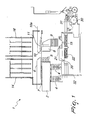
- the load-break switch generally designated by the reference numeral 1, comprises two bars 2, which are supported by insulators 4, each bar ending with a fixed contact of the clamp type 5, an arc quenching horn 6 which is rigidly connected to the bar 2 but is insulated from it by means of an insulating element 7, and a double moving contact 8, which is rigidly coupled to an insulator 9 which connects it to an actuation mechanism.
- the moving contact 8 also is provided with arc quenching horns 10 with pusher springs 11 and with a horn extension 10a, both of which are connected electrically to the moving contact 8.
- Two blowing coils with adapted magnetic cores 12 and 13 are each connected electrically to a bar 2 and to the corresponding fixed horn 6.
- At least one and preferably two quenching chambers with metallic segments 14 and 16 are arranged respectively above each interruption portion; the chambers enclose the arc quenching horns 6 and 10 of the fixed and moving contacts, while the blowing coils with magnetic cores 12 and 13 are segregated by insulating walls.
- the actuation mechanism of the disconnector is constituted by a guide 20, which is rigidly coupled to the fixed structure and on which a bridge 21 with the insulator 9 and the moving contact 8 slides with a linear motion.
- Closure springs are arranged between the ends of the guide 20 and the bridge 21, and opening springs 15 are arranged between the fixed structure and the bridge 21.
- the opening springs 15 and the closure springs 22 are preloaded so that the generated force is scarcely dependent on the stroke.
- the loading of the springs 15 and 11 is such as to accelerate the moving contact and complete the opening stroke in the required time.
- Preloading of the springs 15 when the disconnector is open for an entire closure/opening cycle is performed by means of a gearmotor 30 and lever means 31.
- the gearmotor and the lever means are connected to a fixed footing 32, which is rigidly coupled to the insulators 4.
- the closure movement of the moving contact occurs, looking for example at Figure 1, with a movement to the left of the moving contact 8, while opening occurs by way of a movement to the right of the moving contact 8.
- the metallic continuity of the circuit is maintained by means of the horn contact 10, the blowing coils 12 and 13 and the moving contact.
- the iron magnetic circuit therefore is the seat of a magnetic flux which is proportional to the line current which affects the arc quenching contacts and their extensions and partially affects the quenching chambers 14 and 16.
- the radial component of this flux interacts with the current of the arc that forms after the opening of the horn contacts, pushing the arc along the expansions of the horns 6 and 10 toward the quenching chambers 14 and 16.
- the axial component of the field generated by the spiral and the axial component of the field produced by the coils are added together, accelerating the quenching of the arc and providing faster deionization of the medium, which thus occurs in a time which is comparable to that of an ultrafast switch.
- the load-break switch according to the invention can therefore be used in a closed environment, such as a prefabricated metallic cell, since it is possible to quench the arc in a short time with reduced energy loss without requiring large spaces to contain the arc.
- the load-break switch according to the invention fully achieves the intended aim and objects, since though maintaining test voltages at 50 Hz between the open contacts above 20 kV it can be installed within a closed structure instead of requiring open spaces like known kinds of horn-type disconnectors.
- the load-break switch according to the invention in fact performs a double series interruption between the fixed contact and the moving contact, reducing the stroke of the moving contact for an equal insulation distance, to the benefit of the size of the apparatus and of its intervention times.
- the materials used may be any according to requirements and to the state of the art.
Landscapes
- Engineering & Computer Science (AREA)
- Power Engineering (AREA)
- Arc-Extinguishing Devices That Are Switches (AREA)
- Control Of Transmission Device (AREA)
- Keying Circuit Devices (AREA)
Applications Claiming Priority (1)
| Application Number | Priority Date | Filing Date | Title |
|---|---|---|---|
| ITMI20060421 ITMI20060421A1 (it) | 2006-03-09 | 2006-03-09 | Interruttore di manovra-selezionatore in corrente continua particolarmente per linee di trazione |
Publications (2)
| Publication Number | Publication Date |
|---|---|
| EP1833068A2 true EP1833068A2 (fr) | 2007-09-12 |
| EP1833068A3 EP1833068A3 (fr) | 2008-06-04 |
Family
ID=38024325
Family Applications (1)
| Application Number | Title | Priority Date | Filing Date |
|---|---|---|---|
| EP07003657A Withdrawn EP1833068A3 (fr) | 2006-03-09 | 2007-02-22 | Interrupteur pour courant continu particulièrement pour les lignes de traction |
Country Status (2)
| Country | Link |
|---|---|
| EP (1) | EP1833068A3 (fr) |
| IT (1) | ITMI20060421A1 (fr) |
Family Cites Families (4)
| Publication number | Priority date | Publication date | Assignee | Title |
|---|---|---|---|---|
| FR1541532A (fr) * | 1966-10-22 | 1968-10-04 | Siemens Ag | Dispositif d'extinction de l'arc électrique pour appareils de commutation à courant continu |
| GB1158351A (en) * | 1967-01-30 | 1969-07-16 | Baldwin & Francis Holdings Ltd | Electrical Circuit Interrupters. |
| FR2285700A1 (fr) * | 1974-09-19 | 1976-04-16 | Alsthom Cgee | Dispositif de coupure |
| FR2599548A1 (fr) * | 1986-06-02 | 1987-12-04 | Alsthom | Appareil de coupure a courant continu |
-
2006
- 2006-03-09 IT ITMI20060421 patent/ITMI20060421A1/it unknown
-
2007
- 2007-02-22 EP EP07003657A patent/EP1833068A3/fr not_active Withdrawn
Also Published As
| Publication number | Publication date |
|---|---|
| EP1833068A3 (fr) | 2008-06-04 |
| ITMI20060421A1 (it) | 2007-09-10 |
Similar Documents
| Publication | Publication Date | Title |
|---|---|---|
| EP3223293B1 (fr) | Appareil de commutation électrique et ensemble de chambre à arc et procédé de protection de circuit associé | |
| KR102531873B1 (ko) | 다수의 해머 타격식 진공 인터럽터 용접 파괴 | |
| US20150014277A1 (en) | Interchangeable switching module and electrical switching apparatus including the same | |
| CN105405711A (zh) | 一种双断口真空断路器 | |
| US20190252139A1 (en) | Electrical interruption device | |
| US11211209B2 (en) | Methods and systems for DC current interrupter based on thermionic arc extinction via anode ion depletion | |
| US10269512B2 (en) | Method and device for cutting off an electric current with dynamic magnetic blow-out | |
| CN206312854U (zh) | 断路器的触头装置 | |
| US8901447B2 (en) | Circuit breaker with parallel rated current paths | |
| WO2018145969A1 (fr) | Plaque de séparation d'arc | |
| EP4099522B1 (fr) | Appareillage de commutation isolé au gaz | |
| EP1833068A2 (fr) | Interrupteur pour courant continu particulièrement pour les lignes de traction | |
| CN102237230B (zh) | 用于监控电路的双断路保护开关 | |
| CN100377273C (zh) | 电路断路器的消弧装置 | |
| GB2175450A (en) | Electric switch apparatus | |
| CN107393777B (zh) | 一种具有高分断性能的塑壳断路器 | |
| KR100370103B1 (ko) | 가스절연 개폐기의 단로기 | |
| CN107424856B (zh) | 一种闸板式断路器触头灭弧机构 | |
| US2875302A (en) | Circuit interrupter | |
| JP4786825B2 (ja) | 高電圧遮断器用の駆動ロッド | |
| US20240266127A1 (en) | Low-voltage switch pole | |
| KR20110130914A (ko) | 가스절연개폐장치용 단로기 | |
| KR200413970Y1 (ko) | 가스절연개폐장치의 단로기 및 접지개폐기의 극간 절연가이드 | |
| RU82927U1 (ru) | Дугогасительная система | |
| CA3117799C (fr) | Dispositif d`entrainement electromagnetique pour disjoncteur d`alimentation avec interrupteur a vide |
Legal Events
| Date | Code | Title | Description |
|---|---|---|---|
| PUAI | Public reference made under article 153(3) epc to a published international application that has entered the european phase |
Free format text: ORIGINAL CODE: 0009012 |
|
| AK | Designated contracting states |
Kind code of ref document: A2 Designated state(s): AT BE BG CH CY CZ DE DK EE ES FI FR GB GR HU IE IS IT LI LT LU LV MC NL PL PT RO SE SI SK TR |
|
| AX | Request for extension of the european patent |
Extension state: AL BA HR MK YU |
|
| RIN1 | Information on inventor provided before grant (corrected) |
Inventor name: MAGGIONI, FABRIZIO Inventor name: VIGANO', EMANUELE |
|
| PUAL | Search report despatched |
Free format text: ORIGINAL CODE: 0009013 |
|
| AK | Designated contracting states |
Kind code of ref document: A3 Designated state(s): AT BE BG CH CY CZ DE DK EE ES FI FR GB GR HU IE IS IT LI LT LU LV MC NL PL PT RO SE SI SK TR |
|
| AX | Request for extension of the european patent |
Extension state: AL BA HR MK RS |
|
| AKX | Designation fees paid | ||
| REG | Reference to a national code |
Ref country code: DE Ref legal event code: 8566 |
|
| STAA | Information on the status of an ep patent application or granted ep patent |
Free format text: STATUS: THE APPLICATION IS DEEMED TO BE WITHDRAWN |
|
| 18D | Application deemed to be withdrawn |
Effective date: 20081005 |