EP1833122B1 - Boîtier de terminal de connecteur électrique - Google Patents
Boîtier de terminal de connecteur électrique Download PDFInfo
- Publication number
- EP1833122B1 EP1833122B1 EP07075166.4A EP07075166A EP1833122B1 EP 1833122 B1 EP1833122 B1 EP 1833122B1 EP 07075166 A EP07075166 A EP 07075166A EP 1833122 B1 EP1833122 B1 EP 1833122B1
- Authority
- EP
- European Patent Office
- Prior art keywords
- terminal
- hold
- wall
- housing
- electrical
- Prior art date
- Legal status (The legal status is an assumption and is not a legal conclusion. Google has not performed a legal analysis and makes no representation as to the accuracy of the status listed.)
- Not-in-force
Links
- 230000014759 maintenance of location Effects 0.000 claims description 33
- 230000007704 transition Effects 0.000 claims description 2
- 230000013011 mating Effects 0.000 description 3
- 230000006978 adaptation Effects 0.000 description 2
- 238000003780 insertion Methods 0.000 description 2
- 230000037431 insertion Effects 0.000 description 2
- 239000000463 material Substances 0.000 description 2
- 238000012986 modification Methods 0.000 description 2
- 230000004048 modification Effects 0.000 description 2
- 230000003647 oxidation Effects 0.000 description 2
- 238000007254 oxidation reaction Methods 0.000 description 2
- 238000007747 plating Methods 0.000 description 2
- 238000013459 approach Methods 0.000 description 1
- 239000004020 conductor Substances 0.000 description 1
- 230000008878 coupling Effects 0.000 description 1
- 238000010168 coupling process Methods 0.000 description 1
- 238000005859 coupling reaction Methods 0.000 description 1
- 239000012811 non-conductive material Substances 0.000 description 1
- 238000005192 partition Methods 0.000 description 1
- 230000000717 retained effect Effects 0.000 description 1
- 239000000126 substance Substances 0.000 description 1
Images


Classifications
-
- H—ELECTRICITY
- H01—ELECTRIC ELEMENTS
- H01R—ELECTRICALLY-CONDUCTIVE CONNECTIONS; STRUCTURAL ASSOCIATIONS OF A PLURALITY OF MUTUALLY-INSULATED ELECTRICAL CONNECTING ELEMENTS; COUPLING DEVICES; CURRENT COLLECTORS
- H01R13/00—Details of coupling devices of the kinds covered by groups H01R12/70 or H01R24/00 - H01R33/00
- H01R13/02—Contact members
- H01R13/10—Sockets for co-operation with pins or blades
- H01R13/11—Resilient sockets
- H01R13/113—Resilient sockets co-operating with pins or blades having a rectangular transverse section
-
- H—ELECTRICITY
- H01—ELECTRIC ELEMENTS
- H01R—ELECTRICALLY-CONDUCTIVE CONNECTIONS; STRUCTURAL ASSOCIATIONS OF A PLURALITY OF MUTUALLY-INSULATED ELECTRICAL CONNECTING ELEMENTS; COUPLING DEVICES; CURRENT COLLECTORS
- H01R13/00—Details of coupling devices of the kinds covered by groups H01R12/70 or H01R24/00 - H01R33/00
- H01R13/40—Securing contact members in or to a base or case; Insulating of contact members
- H01R13/42—Securing in a demountable manner
- H01R13/426—Securing by a separate resilient retaining piece supported by base or case, e.g. collar or metal contact-retention clip
-
- H—ELECTRICITY
- H01—ELECTRIC ELEMENTS
- H01R—ELECTRICALLY-CONDUCTIVE CONNECTIONS; STRUCTURAL ASSOCIATIONS OF A PLURALITY OF MUTUALLY-INSULATED ELECTRICAL CONNECTING ELEMENTS; COUPLING DEVICES; CURRENT COLLECTORS
- H01R13/00—Details of coupling devices of the kinds covered by groups H01R12/70 or H01R24/00 - H01R33/00
- H01R13/40—Securing contact members in or to a base or case; Insulating of contact members
- H01R13/42—Securing in a demountable manner
- H01R13/436—Securing a plurality of contact members by one locking piece or operation
- H01R13/4364—Insertion of locking piece from the front
-
- H—ELECTRICITY
- H01—ELECTRIC ELEMENTS
- H01R—ELECTRICALLY-CONDUCTIVE CONNECTIONS; STRUCTURAL ASSOCIATIONS OF A PLURALITY OF MUTUALLY-INSULATED ELECTRICAL CONNECTING ELEMENTS; COUPLING DEVICES; CURRENT COLLECTORS
- H01R13/00—Details of coupling devices of the kinds covered by groups H01R12/70 or H01R24/00 - H01R33/00
- H01R13/02—Contact members
- H01R13/15—Pins, blades or sockets having separate spring member for producing or increasing contact pressure
- H01R13/187—Pins, blades or sockets having separate spring member for producing or increasing contact pressure with spring member in the socket
-
- H—ELECTRICITY
- H01—ELECTRIC ELEMENTS
- H01R—ELECTRICALLY-CONDUCTIVE CONNECTIONS; STRUCTURAL ASSOCIATIONS OF A PLURALITY OF MUTUALLY-INSULATED ELECTRICAL CONNECTING ELEMENTS; COUPLING DEVICES; CURRENT COLLECTORS
- H01R4/00—Electrically-conductive connections between two or more conductive members in direct contact, i.e. touching one another; Means for effecting or maintaining such contact; Electrically-conductive connections having two or more spaced connecting locations for conductors and using contact members penetrating insulation
- H01R4/10—Electrically-conductive connections between two or more conductive members in direct contact, i.e. touching one another; Means for effecting or maintaining such contact; Electrically-conductive connections having two or more spaced connecting locations for conductors and using contact members penetrating insulation effected solely by twisting, wrapping, bending, crimping, or other permanent deformation
- H01R4/18—Electrically-conductive connections between two or more conductive members in direct contact, i.e. touching one another; Means for effecting or maintaining such contact; Electrically-conductive connections having two or more spaced connecting locations for conductors and using contact members penetrating insulation effected solely by twisting, wrapping, bending, crimping, or other permanent deformation by crimping
- H01R4/183—Electrically-conductive connections between two or more conductive members in direct contact, i.e. touching one another; Means for effecting or maintaining such contact; Electrically-conductive connections having two or more spaced connecting locations for conductors and using contact members penetrating insulation effected solely by twisting, wrapping, bending, crimping, or other permanent deformation by crimping for cylindrical elongated bodies, e.g. cables having circular cross-section
- H01R4/184—Electrically-conductive connections between two or more conductive members in direct contact, i.e. touching one another; Means for effecting or maintaining such contact; Electrically-conductive connections having two or more spaced connecting locations for conductors and using contact members penetrating insulation effected solely by twisting, wrapping, bending, crimping, or other permanent deformation by crimping for cylindrical elongated bodies, e.g. cables having circular cross-section comprising a U-shaped wire-receiving portion
- H01R4/185—Electrically-conductive connections between two or more conductive members in direct contact, i.e. touching one another; Means for effecting or maintaining such contact; Electrically-conductive connections having two or more spaced connecting locations for conductors and using contact members penetrating insulation effected solely by twisting, wrapping, bending, crimping, or other permanent deformation by crimping for cylindrical elongated bodies, e.g. cables having circular cross-section comprising a U-shaped wire-receiving portion combined with a U-shaped insulation-receiving portion
Definitions
- This invention relates generally to electrical connectors and, more particularly, to terminal housing of electrical connectors.
- An electrical connector typically includes a conductive terminal for terminating a wire at one end and coupling to a mating terminal at another end, and a non-conductive terminal housing carrying the terminal.
- the terminal housing includes laterally opposed sidewalls and vertically opposed transverse walls between the sidewalls.
- the sidewalls and transverse walls generally define a terminal cavity for receiving the terminal.
- One of the transverse walls is a rigid retention wall including a lock nib projecting into the terminal cavity, and the terminal includes a lock edge that engages the lock nib to retain the terminal in the terminal cavity.
- a flexible hold-down beam Disposed between the transverse walls, a flexible hold-down beam has a protuberance projecting into the terminal cavity for biasing the terminal against the retention wall and into engagement with the lock nib.
- the terminal can laterally move between and vibrate against the terminal housing sidewalls.
- Such terminal-to-housing vibration causes terminal-to-terminal vibration, which leads to localized fretting of mating terminals, thereby leading to plating wear and, eventually, oxidation and concomitant failure of the terminals.
- Current approaches to reducing vibration use too many components, or are too bulky.
- EP-A-1463156 discloses a terminal housing comprising three parts which are secured together.
- the first part includes a front wall, sidewalls and first and second transverse walls.
- the second part includes a rear wall, sidewalls and first and second transverse walls.
- the third part is positioned intermediate the first and second parts and includes a terminal support member.
- US-A-5980318 discloses a terminal housing having a hold-down beam engaging an inserted terminal.
- An electrical connector terminal housing is adapted for carrying an electrical terminal, and includes a rear wall, a front wall, and sidewalls longitudinally extending between the front and rear walls.
- the housing also includes a first transverse wall and a second transverse wall longitudinally extending at least partially between the rear and front walls.
- the housing further includes a cradle between at least one of the sidewalls and the second transverse wall, wherein the cradle is adapted for engagement with corresponding surfaces of the electrical terminal.
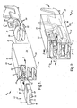
- FIGS. 1 and 2 illustrate an electrical connector assembly 6 according to an exemplary embodiment of the present invention.
- the connector assembly 6 includes an electrical terminal 8 for terminating an electrical element at one end and for engaging a mating terminal (not shown) at another end, a terminal housing 10 for carrying the socket terminal 8, and a wedge or hold-down insert 12 for insertion into a portion of the terminal housing 10 to provide a hold-down force to resiliently retain the terminal 8 therein.
- the terminal housing 10 includes one or more terminal cavities 14 formed therein.
- the terminal housing 10 also includes a front wall 16 and a rear wall 18.
- the front wall 16 has one or more front openings 20 and the rear wall 18 has a rear opening 21, wherein the openings 20, 21 correspond with the terminal cavity 14, which extends front to rear in a longitudinal direction.
- the illustrated terminal cavity 14 is defined in part by relatively rigid, vertically opposed, transverse walls 22, 24 and laterally opposed sidewalls 26, and extends substantially between the front and rear walls 16, 18.
- the transverse walls 22, 24 are attached along their edges to other portions of the terminal housing 10 such as the sidewalls 26, front wall 16, and/or rear wall 18. More specifically, the transverse walls 22, 24 are attached along at least portions of at least two of their edges and preferably along all four of their edges to prevent movement or flexing of the transverse walls 22, 24.
- the transverse walls 22, 24 can be end walls or partition walls of the terminal housing 10 and can longitudinally extend at least partially between the front and rear walls 16, 18.
- the transverse walls 22, 24 extend forward from the rear wall 18 to the front wall 16, and the one transverse wall 24 is also preferably a retention wall 24 carrying a terminal retention feature 28 ( FIG. 3 ), which extends into the terminal cavity 14.
- the retention feature 28 can be a relatively rigid lock nib that includes a sloped surface 30 that starts nearest the rear wall 18 of the terminal housing and terminates at a lock shoulder 32 on the retention feature 28 formed nearest the front wall 16.
- a hold-down beam 34 is disposed substantially vertically opposite with respect to the rigid retention wall 24. As shown, the hold-down beam 34 is a simple beam, but could also be one or more cantilevered beams, or beams of any other suitable geometry. As will be described below, whereas the rigid retention wall 24 carries longitudinal retention forces, the hold-down beam 34 preferably acts a transverse hold-down spring for the terminal 8. A pocket P is provided between the transverse wall 22 and the hold-down beam 34 to facilitate movement or deflection of the hold-down beam 34 and insertion of the hold-down insert 12.
- the hold-down beam 34 is preferably attached at a first fixed end 33 to the transverse wall 22, and extends therefrom in a forward longitudinal direction to terminate in another fixed end 35 that is preferably attached to the front wall 16.
- One or more terminal hold-down protuberances or projections 36 may be provided on the hold-down beam 34 to extend toward the rigid retention wall 24 preferably at a location generally opposite the retention feature 28.
- the projection 36 may be stepped, and may be of any suitable shape, size, and contour.
- the beam 34 includes a ramp 37 generally opposite of the projection 36 for cooperating with the hold-down insert 12 as will be described further below.
- the terminal housing 10 includes features for cradling the electrical terminal 8.
- the terminal 8 would rest directly against an inside surface 25 of the retention wall 24.
- the terminal 8 is preferably cradled so as to be spaced above the retention wall 24.
- the terminal housing 10 is manufactured with a cradle including one or more cradling features, such as laterally opposed fillets 38, between the sidewalls 26 and the retention wall 24.
- the fillet 38 can be of any shape, size, and contour and, for example, can include angled wall portions that include a terminal contact surface 40 for contacting and supporting the terminal 8, a transition radius 42 between the sidewall 26 and the terminal contact surface 40, and a ledge 44 between the terminal contact surface 40 and the retention wall 24.
- such fillets are used between both of the sidewalls 26 and the retention wall 24.
- the fillets 38 are adapted for contact with corresponding surfaces of the terminal 8, as will be described below.
- the terminal housing 10 is constructed and arranged for receiving the electrical terminal 8 in the terminal cavity 14.
- the terminal housing 10 is preferably composed of any suitable electrically non-conductive material, whereas the electrical terminal 8 is composed of any suitable electrically conductive material.
- the electrical terminal 8 may be any suitable type of terminal and, as shown, can be a female or socket terminal.
- the terminal 8 may include a sheath crimp portion 46, a wire crimp portion 48, and a body portion 50.
- the body portion 50 can be open at its forward end, for example to receive a blade of a male or plug terminal (not shown), and the crimp portions 46, 48 are preferably constructed for attachment to an insulated wire, pin, or other electrical component (not shown).
- the terminal body 50 has cradle contact surfaces 52 for contacting the fillets 38 of the terminal housing 10.
- the cradle contact surfaces 52 are preferably rounded or angled as shown.
- the terminal body 50 also has a first surface 54 for contact with a portion of the hold-down beam 34 and a second surface 56 also for contact with another portion of the hold-down beam 34.
- the terminal body 50 has a relief 58, such as a recess or an aperture, for receiving the retention feature 28, and a rigid lock edge 60 associated with the relief 58 for engaging the lock shoulder 32 of the retention feature 28.
- the terminal housing 10 is also constructed and arranged for receiving the hold-down insert 12, which may be composed of any suitable material, such as the same material as the terminal housing 10.
- the hold-down insert 12 can be a separate component as shown, or can be a portion of another terminal housing (not otherwise shown) that is adapted to carry another terminal (not shown) and to be connected to the terminal housing 10.
- the hold-down insert 12 is adapted to be inserted into, and retained within, the pocket P between the wall 22 and the beam 34.
- the hold-down insert 12 preferably includes a front end 62, a rear end 64, a generally planar midsection 66 extending therebetween, and guides 68 on laterally opposed sides of the midsection 60.
- a retaining feature 70 extends from an inside surface 72 of the insert midsection 66.
- the retaining feature 70 is adapted to be trapped within an aperture 74 in the beam 34 of the housing 10.
- a projection 76 extends from the inside surface of the insert midsection 66.
- the beam 34 and projection 76 are adapted to urge the beam 34 into the terminal cavity 14, and the projection 76 is preferably semi-spherical in shape.
- the terminal 8 is inserted through the rear opening 21 in the rear wall 18 and into the terminal cavity 14. As best shown in FIG. 3 , an angled surface 51 of the body 50 of the terminal 8 engages the retention feature 28 and the terminal 8 rides up the sloped surface 30 thereof to lift the terminal 8 generally away from the rigid retention wall 24 and toward the hold-down beam 34. As the terminal 8 rides up the sloped surface 30 of the retention feature 28, the second surface 56 of the terminal 8 engages the stepped projection 36 and the hold-down beam 34 flexes.
- the hold-down beam 34 is resilient such that it tends to recover its rest position under its own inherent resilient bias force.
- the hold-down beam 34 flexes during terminal engagement, but imposes its inherent resilient bias force on the terminal 8 to keep the terminal 8 seated in the cavity 14.
- the beam 34 flexes into the pocket P to accommodate further forward movement of the terminal 8 into the cavity 14 and over the retention feature 28.
- the terminal 8 is pushed forward until the rigid lock edge 60 snaps in front of the retention feature 28 such that the recess or aperture 58 overlies the retention feature 28.
- the hold-down beam 34 can apply a sufficient hold-down force to hold the terminal 8 within the cavity 14 and in engagement with the retention feature 28 of the rigid retention wall 24 and to maintain the rigid lock edge 60 against the lock shoulder 32 of the retention feature 28, thereby preventing inadvertent dislocation and rearward withdrawal of the terminal 8 from the cavity 14.
- the stepped projection 36 rests against the body 50 of the terminal 8, such as in line-to-line contact as shown in phantom line. If the terminal 8 moves in a direction away from the rigid retention wall 24 and toward the other transverse wall 22, the hold-down force offered by the hold-down beam 34 tends to keep the terminal 8 seated and engaged in the terminal cavity 14.
- the housing 10 can be adapted for use with a tanged terminal, or can include a standard flex lock, flex beam, or the like.
- the hold-down insert 12 is inserted into the pocket P to force the terminal 8 into the cradle, against the fillets 38.
- the midsection 66 at its projection 76 is preferably greater in thickness than the pocket P into which the hold-down insert 12 is inserted.
- the hold-down insert 12 advances, its projection 76 rides along the ramp 37 of the hold-down beam 34 and, because the hold-down beam 34 is relatively more flexible than the wall 22, the hold-down insert 12 gradually deflects the hold-down beam 34 into the cavity 14 and firmly against the terminal 8, until further advancement is restrained when the insert retaining feature 70 drops into detent in the beam aperture 74.
- This interference fit of the hold-down insert 12 into the pocket P imposes a hold down force on the terminal 8 sufficient to maintain the terminal 8 cradled against the terminal contact surfaces 40 of the housing 10 and thereby restricts lateral movement of the terminal 8 relative to the housing 10, at least under design intent operating conditions. While use of the insert 12 is preferred, it is contemplated that either the hold-down beam 34 itself, or the insert 12, or both can provide the hold-down force to maintain the terminal 8 cradled against the terminal contact surfaces 40 of the housing 10.
- the present invention thus provides a simple and inexpensive means to laterally restrain an electrical terminal in a terminal housing of an electrical connector.
- the terminal is restrained therein with acceptable terminal-to-housing engagement and disengagement forces, and against lateral movement to avoid vibration between terminal and the housing. Accordingly, the electrical connector will incur relatively less localized fretting, plating wear, oxidation, and concomitant failure of terminals.
- the connector assembly can include a plurality of terminals and inserts, and the connector housing can correspondingly be provided with a plurality of terminal cavities and other features to accommodate the terminals and inserts.
- directional words such as front, rear, top, bottom, upper, lower, radial, circumferential, axial, lateral, longitudinal, vertical, horizontal, transverse, and the like are employed by way of description and not limitation.
Landscapes
- Connector Housings Or Holding Contact Members (AREA)
Claims (7)
- Boîtier de terminal de connecteur électrique (10) adapté pour porter un terminal électrique (8), comprenant :une paroi arrière (18) ;une paroi avant (16) ;des parois latérales (26) s'étendant longitudinalement entre la paroi avant et la paroi arrière (16, 18) ;une première paroi transversale (22) et une seconde paroi transversale (24) s'étendant longitudinalement au moins partiellement entre la paroi arrière et la paroi avant (16, 18) ;au moins un barreau de maintien vers le bas (34) entre la première et la seconde paroi transversale (22, 24), incluant une surface en rampe (37) opposée à la première paroi transversale (22), ledit barreau (34) étant adapté à engager le terminal électrique (8) ;une poche (P) définie entre la première paroi transversale (22) et le barreau de maintien vers le bas (34) et adaptée à accepter un insert de maintien vers le bas (12) à l'intérieur d'elle-même ;l'insert de maintien vers le bas (12) étant adapté à coopérer avec la surface en rampe (3 7) pour forcer le barreau de maintien vers le bas (34) contre le terminal électrique (8) afin de restreindre un mouvement latéral du terminal électrique (8) de manière à réduire des vibrations du terminal vers le boîtier ;caractérisé en ce queledit barreau de maintien vers le bas (34) inclut une ouverture (74) à l'intérieur de lui-même et l'insert de maintien vers le bas (12) inclut un moyen de rétention (70) pour coopérer avec ladite ouverture (74) afin de retenir l'insert de maintien vers le bas (12) dans la poche (P), dans lequel ledit moyen de rétention (70) est adapté à être piégé à l'intérieur de ladite ouverture (74).
- Boîtier de terminal électrique (10) selon la revendication 1, comprenant en outre :un berceau (38) entre l'une au moins des parois latérales (26) et la seconde paroi transversale (24), adapté pour un engagement avec des surfaces de contact de berceau (52) du terminal électrique (8).
- Boîtier de terminal de connecteur électrique (10) selon la revendication 2, dans lequel la seconde paroi transversale (24) est une paroi de rétention (24) portant un moyen de rétention de terminal (28), dans lequel le berceau (38) demeure espacé au-dessus de la paroi de rétention (24).
- Boîtier de terminal de connecteur électrique (10) selon l'une des revendications 2 ou 3, dans lequel le berceau (3 8) inclut des congés latéralement opposés (38) entre les parois latérales (26) et la seconde paroi transversale (24).
- Boîtier de terminal de connecteur électrique (10) selon la revendication 4, dans lequel les congés (38) incluent des surfaces de contact de terminal (40) en angle et adaptées pour un contact avec des surfaces de contact de berceau (52) du terminal électrique (8).
- Boîtier de terminal de connecteur électrique (10) selon la revendication 5, dans lequel les congés (38) incluent en outre des rayons de transition (42) entre les parois latérales (26) et les surfaces de contact de terminal (40) et des rebords (44) entre les surfaces de contact de terminal (40) et la seconde paroi transversale (24).
- Boîtier de terminal de connecteur électrique (10) selon l'une des revendications 4 à 6, dans lequel les congés (38) s'étendent longitudinalement sensiblement entre la paroi avant et la paroi arrière (16, 18).
Applications Claiming Priority (1)
| Application Number | Priority Date | Filing Date | Title |
|---|---|---|---|
| US77974106P | 2006-03-07 | 2006-03-07 |
Publications (3)
| Publication Number | Publication Date |
|---|---|
| EP1833122A2 EP1833122A2 (fr) | 2007-09-12 |
| EP1833122A3 EP1833122A3 (fr) | 2008-12-24 |
| EP1833122B1 true EP1833122B1 (fr) | 2015-01-14 |
Family
ID=38147644
Family Applications (1)
| Application Number | Title | Priority Date | Filing Date |
|---|---|---|---|
| EP07075166.4A Not-in-force EP1833122B1 (fr) | 2006-03-07 | 2007-03-02 | Boîtier de terminal de connecteur électrique |
Country Status (2)
| Country | Link |
|---|---|
| US (1) | US7438585B2 (fr) |
| EP (1) | EP1833122B1 (fr) |
Families Citing this family (14)
| Publication number | Priority date | Publication date | Assignee | Title |
|---|---|---|---|---|
| US8266798B2 (en) | 2009-09-18 | 2012-09-18 | Delphi Technologies, Inc. | Method of making an improved electrical connection with sealed cable core and a terminal |
| US7954235B2 (en) * | 2009-09-18 | 2011-06-07 | Delphi Technologies, Inc. | Method of making a seal about a copper-based terminal |
| US7905755B1 (en) | 2009-09-18 | 2011-03-15 | Delphi Technologies, Inc. | Electrical terminal connection with sealed core crimp |
| JP5508927B2 (ja) * | 2010-04-22 | 2014-06-04 | 日本航空電子工業株式会社 | コネクタ及び防水コネクタ |
| JP5707252B2 (ja) * | 2011-06-24 | 2015-04-22 | 矢崎総業株式会社 | コネクタ |
| KR101572400B1 (ko) * | 2011-10-28 | 2015-11-26 | 스미토모 덴소 가부시키가이샤 | 커넥터 |
| WO2014104122A1 (fr) * | 2012-12-27 | 2014-07-03 | 住友電装株式会社 | Contenant étanche à l'eau |
| US9071016B2 (en) * | 2013-10-03 | 2015-06-30 | Delphi Technologies, Inc. | Electrical connector with a sliding flexible cantilever beam terminal retainer |
| US9300085B2 (en) | 2014-08-20 | 2016-03-29 | Delphi Technologies, Inc. | Electrical wiring assembly and vibration resistant electrical connector for same |
| JP7259444B2 (ja) * | 2019-03-20 | 2023-04-18 | 住友電装株式会社 | コネクタ |
| TWI710167B (zh) * | 2019-11-04 | 2020-11-11 | 大陸商東莞訊滔電子有限公司 | 電連接器 |
| DE102020207331A1 (de) * | 2020-06-12 | 2021-12-16 | Aptiv Technologies Limited | Verbindergehäuse und verbinderanordnung für abgedichtete ringanschlüsse |
| DE102020126541B4 (de) * | 2020-10-09 | 2026-01-29 | Te Connectivity Germany Gmbh | Elektrischer Stecker und Fixiervorrichtung zur Fixierung eines Kontaktelements in einem Gehäuse des elektrischen Steckers |
| JP2023049257A (ja) * | 2021-09-29 | 2023-04-10 | 住友電装株式会社 | コネクタ |
Citations (2)
| Publication number | Priority date | Publication date | Assignee | Title |
|---|---|---|---|---|
| FR2036751A1 (fr) * | 1969-03-17 | 1970-12-31 | Labinal | |
| US20030157833A1 (en) * | 2002-02-15 | 2003-08-21 | Sumitomo Wiring Systems, Ltd. | Connector |
Family Cites Families (7)
| Publication number | Priority date | Publication date | Assignee | Title |
|---|---|---|---|---|
| US5980318A (en) * | 1997-06-25 | 1999-11-09 | General Motors Corporation | Connector with a flexible beam for holding a terminal down and in position |
| US6354873B1 (en) * | 1999-01-29 | 2002-03-12 | Delphi Technologies, Inc. | Snap rail and connector body combination |
| JP2001155810A (ja) * | 1999-11-29 | 2001-06-08 | Yazaki Corp | コネクタ |
| CN100530835C (zh) * | 2002-09-25 | 2009-08-19 | 三菱电线工业株式会社 | 电连接器 |
| JP3763574B2 (ja) * | 2003-03-14 | 2006-04-05 | 日本航空電子工業株式会社 | コネクタ |
| US20040192108A1 (en) * | 2003-03-25 | 2004-09-30 | Tyco Electronics Corporation | Contact stabilization by means of a primary latch reinforcement component |
| DE102005008585B4 (de) * | 2004-02-25 | 2013-05-16 | Sumitomo Wiring Systems, Ltd. | Verbinderanordnung |
-
2007
- 2007-02-27 US US11/711,258 patent/US7438585B2/en not_active Expired - Fee Related
- 2007-03-02 EP EP07075166.4A patent/EP1833122B1/fr not_active Not-in-force
Patent Citations (2)
| Publication number | Priority date | Publication date | Assignee | Title |
|---|---|---|---|---|
| FR2036751A1 (fr) * | 1969-03-17 | 1970-12-31 | Labinal | |
| US20030157833A1 (en) * | 2002-02-15 | 2003-08-21 | Sumitomo Wiring Systems, Ltd. | Connector |
Also Published As
| Publication number | Publication date |
|---|---|
| EP1833122A2 (fr) | 2007-09-12 |
| US20070212950A1 (en) | 2007-09-13 |
| EP1833122A3 (fr) | 2008-12-24 |
| US7438585B2 (en) | 2008-10-21 |
Similar Documents
| Publication | Publication Date | Title |
|---|---|---|
| EP1833122B1 (fr) | Boîtier de terminal de connecteur électrique | |
| US6908345B2 (en) | Electric connector and socket connector | |
| KR101025638B1 (ko) | 커넥터 | |
| EP3190667B1 (fr) | Connecteur | |
| KR101560887B1 (ko) | 커넥터 | |
| JP5282156B1 (ja) | コネクタ | |
| CN111758190B (zh) | 连接器 | |
| US7717755B2 (en) | Electrical connector with improved contacts | |
| US6203385B1 (en) | Electrical contact | |
| US20100248521A1 (en) | Connector assembly featured head-to-head mating interconnection and quick-disconnection therefrom | |
| JP2007165194A (ja) | コネクタ | |
| JP2005166300A (ja) | 大電流用雌端子及びシェル付き大電流用雌端子 | |
| EP2328242B1 (fr) | Connecteur électrique | |
| EP3460920B1 (fr) | Terminal femelle et connecteur | |
| JP6782735B2 (ja) | 端子金具、及び、端子金具とハウジングとの係合構造 | |
| CN112350092B (zh) | 连接器及端子 | |
| JP2020004539A (ja) | 端子金具 | |
| JP2006100232A (ja) | 端子金具及びこれを用いたコネクタ | |
| US7530860B2 (en) | Contact terminal for electrical connector | |
| CN218070237U (zh) | 线对板连接器结构 | |
| US7168982B2 (en) | Connector | |
| US6287153B1 (en) | Cable connector with improved engagement mechanism | |
| JP7405566B2 (ja) | 端子金具、及び、コネクタ構造 | |
| CN209571601U (zh) | 连接器组合 | |
| CN114830454A (zh) | 端子零件及连接器 |
Legal Events
| Date | Code | Title | Description |
|---|---|---|---|
| PUAI | Public reference made under article 153(3) epc to a published international application that has entered the european phase |
Free format text: ORIGINAL CODE: 0009012 |
|
| AK | Designated contracting states |
Kind code of ref document: A2 Designated state(s): AT BE BG CH CY CZ DE DK EE ES FI FR GB GR HU IE IS IT LI LT LU LV MC MT NL PL PT RO SE SI SK TR |
|
| AX | Request for extension of the european patent |
Extension state: AL BA HR MK YU |
|
| PUAL | Search report despatched |
Free format text: ORIGINAL CODE: 0009013 |
|
| AK | Designated contracting states |
Kind code of ref document: A3 Designated state(s): AT BE BG CH CY CZ DE DK EE ES FI FR GB GR HU IE IS IT LI LT LU LV MC MT NL PL PT RO SE SI SK TR |
|
| AX | Request for extension of the european patent |
Extension state: AL BA HR MK RS |
|
| 17P | Request for examination filed |
Effective date: 20090624 |
|
| 17Q | First examination report despatched |
Effective date: 20090623 |
|
| AKX | Designation fees paid |
Designated state(s): AT BE BG CH CY CZ DE DK EE ES FI FR GB GR HU IE IS IT LI LT LU LV MC MT NL PL PT RO SE SI SK TR |
|
| GRAP | Despatch of communication of intention to grant a patent |
Free format text: ORIGINAL CODE: EPIDOSNIGR1 |
|
| INTG | Intention to grant announced |
Effective date: 20140903 |
|
| GRAS | Grant fee paid |
Free format text: ORIGINAL CODE: EPIDOSNIGR3 |
|
| GRAA | (expected) grant |
Free format text: ORIGINAL CODE: 0009210 |
|
| AK | Designated contracting states |
Kind code of ref document: B1 Designated state(s): AT BE BG CH CY CZ DE DK EE ES FI FR GB GR HU IE IS IT LI LT LU LV MC MT NL PL PT RO SE SI SK TR |
|
| REG | Reference to a national code |
Ref country code: GB Ref legal event code: FG4D |
|
| REG | Reference to a national code |
Ref country code: CH Ref legal event code: EP |
|
| REG | Reference to a national code |
Ref country code: IE Ref legal event code: FG4D |
|
| REG | Reference to a national code |
Ref country code: AT Ref legal event code: REF Ref document number: 707455 Country of ref document: AT Kind code of ref document: T Effective date: 20150215 |
|
| REG | Reference to a national code |
Ref country code: DE Ref legal event code: R096 Ref document number: 602007040046 Country of ref document: DE Effective date: 20150305 |
|
| REG | Reference to a national code |
Ref country code: FR Ref legal event code: PLFP Year of fee payment: 9 |
|
| REG | Reference to a national code |
Ref country code: NL Ref legal event code: VDEP Effective date: 20150114 |
|
| REG | Reference to a national code |
Ref country code: AT Ref legal event code: MK05 Ref document number: 707455 Country of ref document: AT Kind code of ref document: T Effective date: 20150114 |
|
| REG | Reference to a national code |
Ref country code: LT Ref legal event code: MG4D |
|
| PG25 | Lapsed in a contracting state [announced via postgrant information from national office to epo] |
Ref country code: LT Free format text: LAPSE BECAUSE OF FAILURE TO SUBMIT A TRANSLATION OF THE DESCRIPTION OR TO PAY THE FEE WITHIN THE PRESCRIBED TIME-LIMIT Effective date: 20150114 Ref country code: SE Free format text: LAPSE BECAUSE OF FAILURE TO SUBMIT A TRANSLATION OF THE DESCRIPTION OR TO PAY THE FEE WITHIN THE PRESCRIBED TIME-LIMIT Effective date: 20150114 Ref country code: ES Free format text: LAPSE BECAUSE OF FAILURE TO SUBMIT A TRANSLATION OF THE DESCRIPTION OR TO PAY THE FEE WITHIN THE PRESCRIBED TIME-LIMIT Effective date: 20150114 Ref country code: BG Free format text: LAPSE BECAUSE OF FAILURE TO SUBMIT A TRANSLATION OF THE DESCRIPTION OR TO PAY THE FEE WITHIN THE PRESCRIBED TIME-LIMIT Effective date: 20150414 Ref country code: FI Free format text: LAPSE BECAUSE OF FAILURE TO SUBMIT A TRANSLATION OF THE DESCRIPTION OR TO PAY THE FEE WITHIN THE PRESCRIBED TIME-LIMIT Effective date: 20150114 |
|
| PG25 | Lapsed in a contracting state [announced via postgrant information from national office to epo] |
Ref country code: GR Free format text: LAPSE BECAUSE OF FAILURE TO SUBMIT A TRANSLATION OF THE DESCRIPTION OR TO PAY THE FEE WITHIN THE PRESCRIBED TIME-LIMIT Effective date: 20150415 Ref country code: NL Free format text: LAPSE BECAUSE OF FAILURE TO SUBMIT A TRANSLATION OF THE DESCRIPTION OR TO PAY THE FEE WITHIN THE PRESCRIBED TIME-LIMIT Effective date: 20150114 Ref country code: IS Free format text: LAPSE BECAUSE OF FAILURE TO SUBMIT A TRANSLATION OF THE DESCRIPTION OR TO PAY THE FEE WITHIN THE PRESCRIBED TIME-LIMIT Effective date: 20150514 Ref country code: AT Free format text: LAPSE BECAUSE OF FAILURE TO SUBMIT A TRANSLATION OF THE DESCRIPTION OR TO PAY THE FEE WITHIN THE PRESCRIBED TIME-LIMIT Effective date: 20150114 Ref country code: LV Free format text: LAPSE BECAUSE OF FAILURE TO SUBMIT A TRANSLATION OF THE DESCRIPTION OR TO PAY THE FEE WITHIN THE PRESCRIBED TIME-LIMIT Effective date: 20150114 Ref country code: PL Free format text: LAPSE BECAUSE OF FAILURE TO SUBMIT A TRANSLATION OF THE DESCRIPTION OR TO PAY THE FEE WITHIN THE PRESCRIBED TIME-LIMIT Effective date: 20150114 |
|
| REG | Reference to a national code |
Ref country code: DE Ref legal event code: R097 Ref document number: 602007040046 Country of ref document: DE |
|
| PG25 | Lapsed in a contracting state [announced via postgrant information from national office to epo] |
Ref country code: EE Free format text: LAPSE BECAUSE OF FAILURE TO SUBMIT A TRANSLATION OF THE DESCRIPTION OR TO PAY THE FEE WITHIN THE PRESCRIBED TIME-LIMIT Effective date: 20150114 Ref country code: SK Free format text: LAPSE BECAUSE OF FAILURE TO SUBMIT A TRANSLATION OF THE DESCRIPTION OR TO PAY THE FEE WITHIN THE PRESCRIBED TIME-LIMIT Effective date: 20150114 Ref country code: RO Free format text: LAPSE BECAUSE OF FAILURE TO SUBMIT A TRANSLATION OF THE DESCRIPTION OR TO PAY THE FEE WITHIN THE PRESCRIBED TIME-LIMIT Effective date: 20150114 Ref country code: DK Free format text: LAPSE BECAUSE OF FAILURE TO SUBMIT A TRANSLATION OF THE DESCRIPTION OR TO PAY THE FEE WITHIN THE PRESCRIBED TIME-LIMIT Effective date: 20150114 Ref country code: MC Free format text: LAPSE BECAUSE OF FAILURE TO SUBMIT A TRANSLATION OF THE DESCRIPTION OR TO PAY THE FEE WITHIN THE PRESCRIBED TIME-LIMIT Effective date: 20150114 Ref country code: LU Free format text: LAPSE BECAUSE OF FAILURE TO SUBMIT A TRANSLATION OF THE DESCRIPTION OR TO PAY THE FEE WITHIN THE PRESCRIBED TIME-LIMIT Effective date: 20150302 Ref country code: CZ Free format text: LAPSE BECAUSE OF FAILURE TO SUBMIT A TRANSLATION OF THE DESCRIPTION OR TO PAY THE FEE WITHIN THE PRESCRIBED TIME-LIMIT Effective date: 20150114 |
|
| REG | Reference to a national code |
Ref country code: CH Ref legal event code: PL |
|
| PLBE | No opposition filed within time limit |
Free format text: ORIGINAL CODE: 0009261 |
|
| STAA | Information on the status of an ep patent application or granted ep patent |
Free format text: STATUS: NO OPPOSITION FILED WITHIN TIME LIMIT |
|
| 26N | No opposition filed |
Effective date: 20151015 |
|
| REG | Reference to a national code |
Ref country code: IE Ref legal event code: MM4A |
|
| PG25 | Lapsed in a contracting state [announced via postgrant information from national office to epo] |
Ref country code: CH Free format text: LAPSE BECAUSE OF NON-PAYMENT OF DUE FEES Effective date: 20150331 Ref country code: IE Free format text: LAPSE BECAUSE OF NON-PAYMENT OF DUE FEES Effective date: 20150302 Ref country code: LI Free format text: LAPSE BECAUSE OF NON-PAYMENT OF DUE FEES Effective date: 20150331 |
|
| PG25 | Lapsed in a contracting state [announced via postgrant information from national office to epo] |
Ref country code: SI Free format text: LAPSE BECAUSE OF FAILURE TO SUBMIT A TRANSLATION OF THE DESCRIPTION OR TO PAY THE FEE WITHIN THE PRESCRIBED TIME-LIMIT Effective date: 20150114 |
|
| REG | Reference to a national code |
Ref country code: FR Ref legal event code: PLFP Year of fee payment: 10 |
|
| PG25 | Lapsed in a contracting state [announced via postgrant information from national office to epo] |
Ref country code: BE Free format text: LAPSE BECAUSE OF FAILURE TO SUBMIT A TRANSLATION OF THE DESCRIPTION OR TO PAY THE FEE WITHIN THE PRESCRIBED TIME-LIMIT Effective date: 20150114 |
|
| PG25 | Lapsed in a contracting state [announced via postgrant information from national office to epo] |
Ref country code: MT Free format text: LAPSE BECAUSE OF FAILURE TO SUBMIT A TRANSLATION OF THE DESCRIPTION OR TO PAY THE FEE WITHIN THE PRESCRIBED TIME-LIMIT Effective date: 20150114 |
|
| REG | Reference to a national code |
Ref country code: FR Ref legal event code: PLFP Year of fee payment: 11 |
|
| PG25 | Lapsed in a contracting state [announced via postgrant information from national office to epo] |
Ref country code: HU Free format text: LAPSE BECAUSE OF FAILURE TO SUBMIT A TRANSLATION OF THE DESCRIPTION OR TO PAY THE FEE WITHIN THE PRESCRIBED TIME-LIMIT; INVALID AB INITIO Effective date: 20070302 |
|
| PG25 | Lapsed in a contracting state [announced via postgrant information from national office to epo] |
Ref country code: CY Free format text: LAPSE BECAUSE OF FAILURE TO SUBMIT A TRANSLATION OF THE DESCRIPTION OR TO PAY THE FEE WITHIN THE PRESCRIBED TIME-LIMIT Effective date: 20150114 |
|
| PG25 | Lapsed in a contracting state [announced via postgrant information from national office to epo] |
Ref country code: PT Free format text: LAPSE BECAUSE OF FAILURE TO SUBMIT A TRANSLATION OF THE DESCRIPTION OR TO PAY THE FEE WITHIN THE PRESCRIBED TIME-LIMIT Effective date: 20150514 |
|
| PG25 | Lapsed in a contracting state [announced via postgrant information from national office to epo] |
Ref country code: TR Free format text: LAPSE BECAUSE OF FAILURE TO SUBMIT A TRANSLATION OF THE DESCRIPTION OR TO PAY THE FEE WITHIN THE PRESCRIBED TIME-LIMIT Effective date: 20150114 |
|
| REG | Reference to a national code |
Ref country code: FR Ref legal event code: PLFP Year of fee payment: 12 |
|
| REG | Reference to a national code |
Ref country code: DE Ref legal event code: R081 Ref document number: 602007040046 Country of ref document: DE Owner name: APTIV TECHNOLOGIES LIMITED, BB Free format text: FORMER OWNER: DELPHI TECHNOLOGIES, INC., TROY, MICH., US |
|
| REG | Reference to a national code |
Ref country code: GB Ref legal event code: 732E Free format text: REGISTERED BETWEEN 20190117 AND 20190123 |
|
| REG | Reference to a national code |
Ref country code: GB Ref legal event code: 732E Free format text: REGISTERED BETWEEN 20190124 AND 20190130 |
|
| PGFP | Annual fee paid to national office [announced via postgrant information from national office to epo] |
Ref country code: GB Payment date: 20200313 Year of fee payment: 14 Ref country code: DE Payment date: 20200228 Year of fee payment: 14 |
|
| PGFP | Annual fee paid to national office [announced via postgrant information from national office to epo] |
Ref country code: FR Payment date: 20200323 Year of fee payment: 14 |
|
| PGFP | Annual fee paid to national office [announced via postgrant information from national office to epo] |
Ref country code: IT Payment date: 20200309 Year of fee payment: 14 |
|
| REG | Reference to a national code |
Ref country code: DE Ref legal event code: R119 Ref document number: 602007040046 Country of ref document: DE |
|
| GBPC | Gb: european patent ceased through non-payment of renewal fee |
Effective date: 20210302 |
|
| PG25 | Lapsed in a contracting state [announced via postgrant information from national office to epo] |
Ref country code: GB Free format text: LAPSE BECAUSE OF NON-PAYMENT OF DUE FEES Effective date: 20210302 Ref country code: FR Free format text: LAPSE BECAUSE OF NON-PAYMENT OF DUE FEES Effective date: 20210331 Ref country code: DE Free format text: LAPSE BECAUSE OF NON-PAYMENT OF DUE FEES Effective date: 20211001 |
|
| PG25 | Lapsed in a contracting state [announced via postgrant information from national office to epo] |
Ref country code: IT Free format text: LAPSE BECAUSE OF NON-PAYMENT OF DUE FEES Effective date: 20210302 |