EP1833123A1 - Unité d'accouplement de prise et de douille - Google Patents
Unité d'accouplement de prise et de douille Download PDFInfo
- Publication number
- EP1833123A1 EP1833123A1 EP06110938A EP06110938A EP1833123A1 EP 1833123 A1 EP1833123 A1 EP 1833123A1 EP 06110938 A EP06110938 A EP 06110938A EP 06110938 A EP06110938 A EP 06110938A EP 1833123 A1 EP1833123 A1 EP 1833123A1
- Authority
- EP
- European Patent Office
- Prior art keywords
- socket
- plug
- housing
- sealing
- female
- Prior art date
- Legal status (The legal status is an assumption and is not a legal conclusion. Google has not performed a legal analysis and makes no representation as to the accuracy of the status listed.)
- Withdrawn
Links
- 238000010168 coupling process Methods 0.000 title claims abstract description 56
- 238000005859 coupling reaction Methods 0.000 title claims abstract description 55
- 230000008878 coupling Effects 0.000 title claims abstract description 53
- 238000007789 sealing Methods 0.000 claims abstract description 126
- 239000004020 conductor Substances 0.000 claims description 11
- 238000006073 displacement reaction Methods 0.000 claims description 7
- 238000003780 insertion Methods 0.000 claims description 6
- 230000037431 insertion Effects 0.000 claims description 6
- 239000000463 material Substances 0.000 description 5
- 230000007246 mechanism Effects 0.000 description 5
- 238000003860 storage Methods 0.000 description 5
- 150000001875 compounds Chemical class 0.000 description 4
- 238000005192 partition Methods 0.000 description 4
- 238000004382 potting Methods 0.000 description 4
- 230000007613 environmental effect Effects 0.000 description 3
- 238000009434 installation Methods 0.000 description 3
- 230000013011 mating Effects 0.000 description 3
- 229910000679 solder Inorganic materials 0.000 description 3
- XLYOFNOQVPJJNP-UHFFFAOYSA-N water Substances O XLYOFNOQVPJJNP-UHFFFAOYSA-N 0.000 description 3
- 238000005452 bending Methods 0.000 description 2
- 230000015572 biosynthetic process Effects 0.000 description 2
- 238000011109 contamination Methods 0.000 description 2
- 230000002349 favourable effect Effects 0.000 description 2
- 210000003746 feather Anatomy 0.000 description 2
- 230000001681 protective effect Effects 0.000 description 2
- 238000005476 soldering Methods 0.000 description 2
- 238000004026 adhesive bonding Methods 0.000 description 1
- 238000005266 casting Methods 0.000 description 1
- 230000006835 compression Effects 0.000 description 1
- 238000007906 compression Methods 0.000 description 1
- 238000010276 construction Methods 0.000 description 1
- 238000005260 corrosion Methods 0.000 description 1
- 230000007797 corrosion Effects 0.000 description 1
- 230000002950 deficient Effects 0.000 description 1
- 230000001419 dependent effect Effects 0.000 description 1
- 239000000428 dust Substances 0.000 description 1
- 230000005484 gravity Effects 0.000 description 1
- 238000000227 grinding Methods 0.000 description 1
- 230000000977 initiatory effect Effects 0.000 description 1
- 238000003754 machining Methods 0.000 description 1
- 238000000034 method Methods 0.000 description 1
- 238000003801 milling Methods 0.000 description 1
- 230000004297 night vision Effects 0.000 description 1
- 230000005693 optoelectronics Effects 0.000 description 1
- 230000000149 penetrating effect Effects 0.000 description 1
- 230000008569 process Effects 0.000 description 1
- 239000003566 sealing material Substances 0.000 description 1
- 239000007921 spray Substances 0.000 description 1
- 238000005507 spraying Methods 0.000 description 1
- 230000007704 transition Effects 0.000 description 1
Images



Classifications
-
- H—ELECTRICITY
- H01—ELECTRIC ELEMENTS
- H01R—ELECTRICALLY-CONDUCTIVE CONNECTIONS; STRUCTURAL ASSOCIATIONS OF A PLURALITY OF MUTUALLY-INSULATED ELECTRICAL CONNECTING ELEMENTS; COUPLING DEVICES; CURRENT COLLECTORS
- H01R13/00—Details of coupling devices of the kinds covered by groups H01R12/70 or H01R24/00 - H01R33/00
- H01R13/44—Means for preventing access to live contacts
- H01R13/447—Shutter or cover plate
- H01R13/453—Shutter or cover plate opened by engagement of counterpart
- H01R13/4538—Covers sliding or withdrawing in the direction of engagement
-
- H—ELECTRICITY
- H01—ELECTRIC ELEMENTS
- H01R—ELECTRICALLY-CONDUCTIVE CONNECTIONS; STRUCTURAL ASSOCIATIONS OF A PLURALITY OF MUTUALLY-INSULATED ELECTRICAL CONNECTING ELEMENTS; COUPLING DEVICES; CURRENT COLLECTORS
- H01R12/00—Structural associations of a plurality of mutually-insulated electrical connecting elements, specially adapted for printed circuits, e.g. printed circuit boards [PCB], flat or ribbon cables, or like generally planar structures, e.g. terminal strips, terminal blocks; Coupling devices specially adapted for printed circuits, flat or ribbon cables, or like generally planar structures; Terminals specially adapted for contact with, or insertion into, printed circuits, flat or ribbon cables, or like generally planar structures
- H01R12/70—Coupling devices
- H01R12/71—Coupling devices for rigid printing circuits or like structures
- H01R12/712—Coupling devices for rigid printing circuits or like structures co-operating with the surface of the printed circuit or with a coupling device exclusively provided on the surface of the printed circuit
- H01R12/716—Coupling device provided on the PCB
Definitions
- the invention relates to a socket-plug coupling unit according to the preamble of claim 1.
- socket-plug coupling units have a socket and a plug, each with electrical contacts, via which an electrical connection can be made.
- Such coupling units are used, for example, to make connections - e.g. for a power supply, for components arranged in different parts of the device, such as operating elements, or for data lines - used in high-quality electrical, electronic or opto-electronic devices.
- one side of the socket and plug is for coupling the elements together - generally by plugging the plug into the socket - provided.
- the socket and / or plug are usually installed, e.g. in a device as mentioned above.
- the socket is selected as the current-carrying active element or the current-carrying element is referred to as a socket.
- the current-carrying element it is necessary that its electrical contacts are sealed to the outside and thus protected against penetrating water and dirt.
- sockets and / or plugs which are used in devices that are used outdoors and, if necessary, in all weather conditions, this tightness against water and pollution is required.
- a user is often faced with the problem that require different applications, the decoupling of socket and plug, in the uncoupled state, both socket and plug are exposed to environmental influences, but the contacts must not be wet or dirty.
- sealing elements such as covers or sealing caps are known, which cover the area of the electrical contacts - tight - in the uncoupled state.
- covers or sealing caps are attached, for example via a cord or a tape to an electrical device, in which socket and / or plug are installed.
- the requirement for good accessibility of the sealing elements presupposes that the coupling unit or the corresponding element of the coupling unit is in a readily accessible position - e.g. a device - must be attached.
- a disadvantage of such a seal is given by the fact that in the period between removal of the seal and reaching the coupled state, the electrical contacts are not protected against the outside. Thereby, e.g. Raindrops, sea spray or dust penetrate into the contact area and lead to failure of the electrical connection due to corrosion, contamination or leakage currents.
- an object of the present invention is to provide a simplified with respect to their sealing and handling socket-connector coupling unit.
- the invention is formed by the formation of the active element of the female connector coupling unit with a sealing element, by the arrangement and storage of the sealing element and by the formation of the passive element, a coupling unit with a both in the coupled and in the decoupled state to the outside dense active element provided.
- the leak-tightness is achieved, so to speak, automatically by means of the unit, in so far as the user does not - e.g. External or separate - means for sealing the active element must be operated, which greatly simplifies the handling for the user.
- the active element is the current-carrying or current-carrying element of the unit.
- the active element is referred to as a socket element and the passive element as a plug element.
- the female member has a female housing and disposed in the female housing electrical socket contact elements. At its intended for contact with the connector contact elements page the female contact elements are completely within the socket housing.
- the male member is inserted through an opening in the female housing of the female member.
- the plug element is guided out of the socket housing, at least until the electrical connection is disconnected.
- the sealing element is movably mounted in the socket housing such that it is pressed in the uncoupled state of the female connector coupling unit medium or directly against the edge of the opening of the female housing, so that it is sealed to the outside.
- a component - e.g. the plug housing - the plug member medium or pressed directly against the edge of the opening so that the opening is sealed even in the coupled state.
- an opening-side sealing of the socket contact elements arranged in the socket housing is provided both in the coupled and in the decoupled state, wherein the sealing mechanism is actuated automatically by the coupling process.
- the inventive construction further the tightness is interrupted neither during coupling nor during uncoupling.
- the in the socket housing - possibly centered - mounted sealing element is formed for example as a sealing plug.
- it is adapted to the desired function, ie the underside - pointing to the plug element or the opening - the opening adapted such that the correspondingly tight closure is made possible.
- This is achieved, for example, by a design that has a medium or immediate circumferential connection between the sealing element and Opening causes, for example, by a covering the opening, around the opening edge circumferentially fitting sealing element.
- the bearing in the socket housing is such that the sealing element during execution or removal of the plug member or when running or removed plug member medium or is pressed directly against the edge of the opening. If storage via a spring element or a plurality of spring elements, the sealing element is pressed at uncoupled socket and plug element by the force of the spring elements down - towards opening - up against the opening edge respectively biased. In order to apply the required spring force, storage over at least two spring elements is low.
- the spring elements can represent conventional compression springs, such as coil springs.
- the sealing element preferably has receptacles for the spring elements, for example adapted recesses, such as blind holes.
- the spring elements are arranged in recordings, a stable position of the spring elements - and thus reliable storage of the sealing element - ensures, and avoids a possible bending of the spring elements. The same can be stored loose in the respective recordings.
- fastening means such as hooks or eyes, may be provided for fastening the spring elements in the receptacles, so that they do not fall out when the socket housing is opened.
- the male member When coupling the female member with the male member, the male member, as mentioned above, inserted through the opening in the female housing, as inserted or inserted.
- the dome operation takes place by the connector element on the top side or plug socket side (see, for example, Figure 1) is attached to the sealing element and moves during insertion of the sealing element into the socket housing inside, wherein the plug element occupies the corresponding free space in the socket housing.
- the movement in particular represents an axial displacement in the direction of the opening,
- the side opposite the female connector side is the female terminal side to which the female member is connected via the female contact elements to other conductor elements, such as a printed circuit board of a device.
- the socket element can also be designed such that the connection takes place elsewhere, for example laterally.
- corresponding counter-contours may be provided on the sealing element and / or on the plug element.
- the sealing element on the underside has a circumferential chamfer for a corresponding chamfer-shaped contour of the plug housing.
- Sealing element and connector housing can also have connecting elements, such as latching elements or recesses and corresponding pins or hooks. Such contours or fasteners serve as an insertion aid and possibly centering.
- the sealing element is in the decoupled and the plug element in the coupled state medium or directly on the edge of the opening.
- a sealing component is arranged circumferentially at the edge region of the opening, then the sealing element and the plug housing preferably rest indirectly on the edge of the opening via the sealing component.
- a suitable sealing component represents a sealing ring with a sealing lip. The inwardly directed sealing lip cooperates with the sealing element and the plug element, so that the opening is tightly sealed against water, contamination, etc.
- sealing ring Under seal in this context is not exclusively to understand annular sealing ring, but one of the shape of the opening adapted sealing ring, for example, may be round, oval, approximately rectangular or square.
- the sealing ring or the sealing component is formed from conventional sealing materials, for example of rubber-like material, and firmly connected to the housing. The connection can be made via a material bond - eg by gluing, spraying or vulcanising, depending on the materials.
- the plug element may have a further seal.
- a seal could be attached to the connector housing which cooperates with the sealing component of the female member, e.g. Sealing component and seal could be formed with mating parts.
- a seal of the plug element could also be provided as an alternative to a sealing component of the socket element. In this case, the sealing element of the socket element in the uncoupled state and the seal of the plug element in the coupled state, the opening would close tightly. Additionally or alternatively, a seal could also be attached or applied to the sealing element.
- the female housing may be composed of at least two housing parts. If the parts are releasably secured, it is possible to open the housing and replace defective components.
- the housing parts for example, an upper and lower housing part or a right and left housing part.
- the assembly can be done by means of mating.
- alternative connections in particular via a releasable positive connection, such as latching or snap connections, with the usual corresponding connection partners possible.
- Another alternative is a - e.g. Exterior - locking dar.
- the socket housing can also be designed in one piece.
- socket contact elements In the socket housing at least two electrically conductive socket contact elements are used.
- a female connector coupling unit with two female and male contact elements could be formed for example as a jack.
- contact elements In general, several, for example ten, contact elements are used.
- the socket contact elements each have an area for one Contact with conductor elements or connection to conductor elements, such as a printed circuit board or wires, on and in each case an area for contact with the plug contact elements. If the region for the contact with the plug contact elements is formed as a curved contact point - for example, by a soldered layer or a surface curvature produced by a stamping bending process - contact can also be produced even with slightly twisted or shifted socket and / or plug contact elements.
- the terminal area of the female contact elements is generally outside the female housing such that a single terminal, e.g. by soldering, is possible. Since this area is usually installed in a device or a cable housing, it is not exposed to external influences.
- the connector contact region having the side of the female contact elements is completely within the female housing - this side of the female contact elements is therefore also completely sealed off from the outside.
- the socket contact elements are advantageously made elastic.
- the female contact elements are formed elastically, for example, resiliently, they can yield when moving the sealing element - they are, for example bent outwards and feathers after further passing past the sealing element back to the starting position so that they the plug contact elements of the inserted through the opening plug element with sufficient pressure to contact.
- the sealing element is for example mounted centrally between the socket contact elements and expanded so far in the lower area that in the decoupled state, a circumferential connection with the opening is given, and it is tapered towards its center. In the decoupled state, the "relaxed" socket contact elements abut against the tapered region of the sealing element. When inserting the plug element is now the Displaced sealing element in the coupling direction.
- the socket contact elements are bent when moving the same outwards and feathers after passing the sealing element back into the "relaxed" position, where they then rest with the required contact pressure at the corresponding contact points or contact surfaces of the plug contact elements of the inserted plug element ,
- a centered arrangement of the sealing element in the socket housing is particularly favorable if the socket contact elements are also arranged symmetrically to the middle of the bush - for example, left and right to the central transverse axis or perpendicular thereto, or radially symmetrical to the middle of the bushing.
- the sealing element can also be arranged non-centered, e.g. in one-sided arrangement of the socket contact elements.
- the arrangement and displacement of the sealing element can still be supported by guide elements, such as guides on the sealing element and corresponding rails on the socket housing or vice versa.
- the counterpart to the socket element forms the plug element.
- the plug element comprises a plug housing with plug contact elements.
- the extension of the male part of the male member to be inserted corresponds to the opening of the female housing through which the male member is inserted upon coupling.
- the part to be inserted may be the plug housing or a part of the plug housing.
- the plug contact elements for example in the form of a jack plug, form the part to be inserted.
- the plug contact elements may be injected or molded into the housing.
- the plug contact elements with the plug housing housing forming material, such as plastic, so encapsulated that they are flat to side surfaces of the plug housing.
- the housing may also be formed only as a holding part for the plug contact elements, for example as a flange in which the contacts are held.
- the plug contact elements are arranged corresponding to the arrangement of the socket contact elements. With corresponding - e.g. more resilient - trained socket contact elements, the plug contact elements can also be recessed in the connector housing. Likewise, an outer protective cover could be provided around the plug contact elements, which is displaced (pushed down) during coupling and is pushed back over the plug contact elements during uncoupling, for example automatically by a spring mechanism. At the plug connection side, the plug element via the plug contact elements in the usual manner to corresponding electrically conductive conductor elements, such as wires, etc. can be connected.
- Plug and / or socket elements may further be made gas-tight, e.g. by casting cavities of the plug and / or socket housing with a corresponding potting compound.
- the gas-tight design is especially in relation to an installation of plug or socket element in a gas-tight viewing device, such as a night vision device, providable.
- the plug element is installed in the viewing device.
- the socket and plug element are not self-locking. It can be assigned to the female and male element an internal or external locking mechanism. Likewise, the locking may optionally be provided on the device in which the installation takes place. Plug and / or socket element can also be installed in handle-like, provided for manual handling, outer housing with cables, the mechanical locking can be done by appropriate design of the outer housing, for example by means of pawls or bayonet locks.
- a female member B and a male member S of a female connector coupling unit is shown in the disconnected state.
- the isometric views show the elements in partial front and side views and in partial plan view in Figure 1 and partial bottom view in Figure 2.
- the side of the female element B, on which the coupling with the male element S is done, is referred to as female connector side BS.
- the side of the plug element B, on which the coupling with the plug element S takes place is referred to as the plug socket side SB.
- the side of the female or male element B or S, at which the connection to further conductor elements takes place, is referred to as the female side BA or the male side SA.
- the female housing of the female member B of the illustrated embodiment is composed of a first, lower-female plug-side housing part 4 and a second, upper-female-terminal-side-housing part, hereinafter referred to as Contact holder 5 is called composed via a plug connection.
- Contact holder 5 is called composed via a plug connection.
- latching hooks 8 are provided on the lower housing part, which engage when plugged into recesses 8 'of the contact holder 5 provided for this purpose. After mating the parts are positively connected.
- the arranged in the socket housing socket contacts 7 are inserted in the contact holder 5 and form the right and left of and symmetrical to the central transverse axis QA of the female element B each have a linear arrangement.
- a holding plate 6 is shown in the illustrated embodiment, in which the female contact elements 7 are soldered to the female terminal side BA at solder joints 14.
- the holding plate 6 represents, for example, an independent printed circuit board or a part of a printed circuit board of a device.
- the female contact elements 7 lie completely in the socket housing.
- the female housing has on the underside - female connector side - an opening H, through which the male member S can be inserted with its male connector side SB.
- the coupled state is reached, in which contact socket contact elements 7 and plug contact elements 2.
- a sealing ring 3 is arranged around the circumference as a sealing component.
- the sealing ring 3 is adapted to the geometry of the opening H and here of oval shape.
- the arrangement and design of the sealing ring 3 can be seen in more detail in Figures 3 to 5.
- the electrical socket contact elements 7 are completely protected in the housing interior to the outside.
- the plug element S has plug contact elements 2 corresponding to the socket contact elements 7, which are encapsulated with the material, eg plastic, which forms the plug housing 1.
- the plug contact elements 2 are inserted in the connector housing 1 such that their - for contact with the Socket contact elements 7 provided - contact surfaces lie in a plane with the outer surface of the connector housing 1.
- the plug element S can be connected, for example soldered, via the plug contact elements 2, for example to a printed circuit board or wires or flat conductors.
- the plug element S is designed gas-tight here, by the hollow region between the plug contact elements 2 and the connector housing 1 is potted with a potting compound 9.
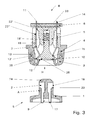
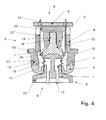
- Figures 3 and 4 show a section through the female connector coupling unit along the central longitudinal axis LA (see Figure 1), wherein the female connector coupling unit is shown in Figure 3 in the uncoupled and in Figure 4 in the coupled state. From the sectional representations of the uncoupled and coupled state, in particular the functions of the respective components or the design of the respective components are understandable.
- the socket contacts 7 are designed to be resilient and slightly angled in their lower - socket-connector-side - area, so that they rest in the disengaged state of Figure 3 on the sealing plug 10.
- the region of the socket contacts 7, which bears against the sealing plug 10, forms the contact region for the plug contacts 2.
- the contact region is provided with a soldered-on layer, which forms a curved contact point 15.
- the sealing plug 10 When inserting the plug element S through the opening H in the socket element B, the sealing plug 10 is pushed by means of the plug element S in the socket housing. Due to the shape of the sealing plug 10, the socket contacts 7 are spread when moving the sealing plug 10 and bent outwards. If the sealing plug 10 is pushed over the contact points 15, the socket contacts 7 spring back into their previous position, so that - as shown in FIG. 4 - when the socket element B and the plug element S are coupled, their contact points 15 contact the planar contact surfaces 16 of the plug contact elements 2 , In the situation according to Figure 4 are the Socket contact elements 7 and connector contact elements 2 with corresponding contact pressure to each other, so that an electrical connection is formed.
- the plug element S is pushed through the opening H of the female housing.
- the plug element S and the sealing plug 10 are profiled profiled with corresponding contours - the plug element S has a chamfered plug contours 24, the sealing plug 10 is also a chamfered contour 25.
- the male element S is centrally attached to the sealing plug 10 and this when pushing of the plug element S in the coupling direction - ie in the direction of plug connection side SA - pushed axially (in the direction of the longitudinal axis) in the socket housing.
- the socket housing has around the opening H a circumferential groove 13 into which a corresponding profile 13 'having sealing ring 3 is inserted. Sealing ring 3 and female housing are connected cohesively.
- the seal 3 further has a circumferential on its inner circumference sealing lip 12, which forms a watertight closure of the opening H in cooperation with the sealing element 10 in the female housing ( Figure 3) or with the connector housing 1 ( Figure 4). By the sealing lip 12 is also stripped on insertion of the connector element S in the socket housing any dirt or moisture from the connector housing 1 or from the connector contact elements 2.
- the opening H is sealed watertight by means of sealing lip 12 and sealing plug 10.
- the sealing plug 10 is spring-loaded in the contact holder 5. By the force of the spring 11, the sealing plug 10 is biased against the sealing lip 12, wherein sealing plug 10 and sealing lip 12 are designed such that a circumferential connection is given.
- the socket contacts 7 are fully protected even in the disengaged state against the outside, so that in all modes of the socket-plug coupling unit, the tightness of the current-carrying element is ensured.
- the displacement and location of the sealing plug 10 in the socket housing is supported by guide elements - e.g. as shown by rails 18 'on the contact holder 5 and guides 18 on the sealing plug 10th
- the female contact elements 7 are inserted into slot-shaped openings of the female contact holder 5.
- the slot intermediate walls 22 of the contact holder 5 prevent lateral displacement of the socket contact elements 7.
- the slot partition walls 22 are clearly visible in FIG.
- the socket contact elements rest on contact support surfaces 22 ', 22 "of the contact holder 5.
- the socket contact elements 7 are soldered to the socket contact elements 7 in the solder joints 14. It should be understood that this illustration is purely exemplary and the socket contacts 7 with alternative conventional electrical guide elements are connectable.
- the section through the plug element S shows the plug contacts 2 injected in the plug housing 1, which are encapsulated in such a way that a positive connection in all directions is ensured.
- the contact surfaces 16 of the plug contacts 2 are flush with the corresponding outer surfaces A of the plug housing 1.
- the outer surfaces A of the plug housing 1 are as smooth and free of heels grooves or ridges performed, for example, by machining, such as milling, planing or grinding, the surface transition 23 between the connector housing 1 and plug contacts 2, whereby, inter alia, a long durability and good Abstreiffunktion on the sealing lip 12 is favored.
- At the ends 17 of the plug contact elements 2, which are opposite to the contact surfaces 16 substantially, conventional conductor elements are connected in a conventional manner.
- the plug element S is gas-tight closable.
- the plug element S is gas-tight.
- FIG. 5 shows a section through the socket-plug coupling unit along its central transverse axis QA (see FIG. 1), wherein the socket-plug coupling unit is shown in the coupled state-analogous to FIG.
- the storage of the sealing plug 10 in the socket housing or in the contact holder 5 is clearly visible.
- two springs 11 - shown here as helical springs - the sealing plug 10 is movably mounted in the contact holder 5 and spring-loaded.
- Contact holder 5 and sealing plug 10 have receptacles for the springs, the contact holder 5 in the form of bearing surfaces 26 and the sealing plug 10 in the form of blind holes 27th
- the sealing plug 10 is pushed against the spring force approximately in the extension of the inserted plug element S in the socket housing respectively pressed. Since the female-male coupling unit is not self-locking, a corresponding outer mechanical lock is used to hold the unit in the coupled state. It is of course also possible to form the inventive socket-connector coupling unit with a self-locking mechanism.
- socket element B and / or plug element S are installed in a device, then the functions and the design of the device adapted Verrieglungskomponenten - eg of the device - for locking socket and plug element B, S are used.
- the female member B on the female housing a flange 19 and the male member S on the connector housing 1, a flange 20, which flanges 19 and 20, for example, glued or cast in electronic devices.
- the respective flanges 19 and 20 for installation of female element B and plug element S may be favorable for a variety of applications.
- the plug element S and / or the socket element B are in FIG handle-like, provided for manual handling, outer housing fitted with cables, the mechanical locking by appropriate design of the outer housing, as done by pawls or bayonet locks.
- FIG. 6 shows a sectional illustration along the central longitudinal axis (LA) in an isometric view of the contact holder 5 with the socket contact elements 7 and the sealing plug 10 of the socket element.
- the slots and the slot partitions 22 for the female contact elements 7 of the contact holder 5 are clearly visible.
- the slot partitions 22 further have contact fixing cams 21 to securely prevent displacement of the socket contacts 7 between the slot partitions 22.
- the correct position of the female contact elements 7 is ensured during assembly before further connecting the female contact elements 7 on the female terminal side, such as soldering in the retaining plate - so, for example, initiation of mechanical stress in the solder joints 14 is prevented.
- the female contact elements 7 are further secured by the sealing plug 10 against lateral displacement by this laterally tooth-shaped holding elements 28, between which the female contacts 7 are arranged.
Landscapes
- Connector Housings Or Holding Contact Members (AREA)
Priority Applications (1)
| Application Number | Priority Date | Filing Date | Title |
|---|---|---|---|
| EP06110938A EP1833123A1 (fr) | 2006-03-10 | 2006-03-10 | Unité d'accouplement de prise et de douille |
Applications Claiming Priority (1)
| Application Number | Priority Date | Filing Date | Title |
|---|---|---|---|
| EP06110938A EP1833123A1 (fr) | 2006-03-10 | 2006-03-10 | Unité d'accouplement de prise et de douille |
Publications (1)
| Publication Number | Publication Date |
|---|---|
| EP1833123A1 true EP1833123A1 (fr) | 2007-09-12 |
Family
ID=36763241
Family Applications (1)
| Application Number | Title | Priority Date | Filing Date |
|---|---|---|---|
| EP06110938A Withdrawn EP1833123A1 (fr) | 2006-03-10 | 2006-03-10 | Unité d'accouplement de prise et de douille |
Country Status (1)
| Country | Link |
|---|---|
| EP (1) | EP1833123A1 (fr) |
Cited By (4)
| Publication number | Priority date | Publication date | Assignee | Title |
|---|---|---|---|---|
| EP2104183A1 (fr) * | 2008-03-18 | 2009-09-23 | ABB Schweiz AG | Dispositif de raccordement électrique et raccord |
| WO2009121083A1 (fr) | 2008-03-31 | 2009-10-08 | Peter Straka | Douille pour lampe tubulaire |
| DE102017100538B3 (de) | 2017-01-12 | 2018-05-09 | Knorr-Bremse Systeme für Nutzfahrzeuge GmbH | Elektrische Steckverbindung aus einem Stecker und einem Gegenstecker sowie elektrische oder elektro-pneumatische Bremseinrichtung eines Fahrzeugs |
| WO2024061603A1 (fr) * | 2022-09-23 | 2024-03-28 | Bayerische Motoren Werke Aktiengesellschaft | Système de douille, véhicule à moteur et système d'alimentation |
Citations (7)
| Publication number | Priority date | Publication date | Assignee | Title |
|---|---|---|---|---|
| FR1371514A (fr) * | 1962-10-03 | 1964-09-04 | Bbc Brown Boveri & Cie | Accouplement électrique formé de deux têtes d'accouplement |
| GB1203852A (en) * | 1967-05-19 | 1970-09-03 | Bolkow Gmbh | Electric plug connection |
| FR2529396A1 (fr) * | 1982-06-24 | 1983-12-30 | Souriau & Cie | Connecteur electrique etanche utilisable en milieu liquide |
| DE29608612U1 (de) * | 1996-05-11 | 1996-08-08 | Franz Binder GmbH & Co Elektrische Bauelemente KG, 74172 Neckarsulm | Elektrischer Steckverbinder |
| DE19809801A1 (de) * | 1998-03-09 | 1999-09-16 | Kromberg & Schubert | Elektrische Kontaktvorrichtung, insbesondere für Fahrzeuge |
| GB2338632A (en) * | 1998-06-16 | 1999-12-22 | Pifco Ltd | Metal sheathed planar element: Edge connector with shutter |
| US20030045150A1 (en) * | 2001-08-29 | 2003-03-06 | Harting Automotive Gmbh & Co. Kg. | Socket for a contamination-protected plug connection as well as plug connection |
-
2006
- 2006-03-10 EP EP06110938A patent/EP1833123A1/fr not_active Withdrawn
Patent Citations (7)
| Publication number | Priority date | Publication date | Assignee | Title |
|---|---|---|---|---|
| FR1371514A (fr) * | 1962-10-03 | 1964-09-04 | Bbc Brown Boveri & Cie | Accouplement électrique formé de deux têtes d'accouplement |
| GB1203852A (en) * | 1967-05-19 | 1970-09-03 | Bolkow Gmbh | Electric plug connection |
| FR2529396A1 (fr) * | 1982-06-24 | 1983-12-30 | Souriau & Cie | Connecteur electrique etanche utilisable en milieu liquide |
| DE29608612U1 (de) * | 1996-05-11 | 1996-08-08 | Franz Binder GmbH & Co Elektrische Bauelemente KG, 74172 Neckarsulm | Elektrischer Steckverbinder |
| DE19809801A1 (de) * | 1998-03-09 | 1999-09-16 | Kromberg & Schubert | Elektrische Kontaktvorrichtung, insbesondere für Fahrzeuge |
| GB2338632A (en) * | 1998-06-16 | 1999-12-22 | Pifco Ltd | Metal sheathed planar element: Edge connector with shutter |
| US20030045150A1 (en) * | 2001-08-29 | 2003-03-06 | Harting Automotive Gmbh & Co. Kg. | Socket for a contamination-protected plug connection as well as plug connection |
Cited By (6)
| Publication number | Priority date | Publication date | Assignee | Title |
|---|---|---|---|---|
| EP2104183A1 (fr) * | 2008-03-18 | 2009-09-23 | ABB Schweiz AG | Dispositif de raccordement électrique et raccord |
| US7641506B2 (en) | 2008-03-18 | 2010-01-05 | Abb Schweiz Ag | Electrical connection device and connector |
| WO2009121083A1 (fr) | 2008-03-31 | 2009-10-08 | Peter Straka | Douille pour lampe tubulaire |
| DE102017100538B3 (de) | 2017-01-12 | 2018-05-09 | Knorr-Bremse Systeme für Nutzfahrzeuge GmbH | Elektrische Steckverbindung aus einem Stecker und einem Gegenstecker sowie elektrische oder elektro-pneumatische Bremseinrichtung eines Fahrzeugs |
| US10756469B2 (en) | 2017-01-12 | 2020-08-25 | Knorr-Bremse Systeme Fuer Nutzfahrzeuge Gmbh | Electric plug of an electric plug connection comprising the plug and a mating plug |
| WO2024061603A1 (fr) * | 2022-09-23 | 2024-03-28 | Bayerische Motoren Werke Aktiengesellschaft | Système de douille, véhicule à moteur et système d'alimentation |
Similar Documents
| Publication | Publication Date | Title |
|---|---|---|
| DE102013213336B4 (de) | Elektrischer steckverbinder, ladedose und steckverbindersystem für ein elektro- oder hybridfahrzeug | |
| DE10028198B4 (de) | Steckverbindungselement | |
| DE112012003730T5 (de) | Kopplungsverbinder und Zusammenbauverfahren dafür | |
| DE10041837A1 (de) | Wasserdichter Stecker | |
| WO2016138982A1 (fr) | Procédé de montage d'un connecteur coudé à fiche | |
| DE1615001B2 (de) | Elektrische steckvorrichtung | |
| DE19809492C2 (de) | Elektrischer Verbinder | |
| DE102011007739B4 (de) | Stecker | |
| DE202012001638U1 (de) | Gehäuse für eine Kontakteinrichtung | |
| EP1088374B1 (fr) | Adaptateur de traversee pour armoire electrique | |
| DE102007047251A1 (de) | Selbstjustierender Gerätesteckverbinder | |
| DE102005021615A1 (de) | Gehäuseglied mit Steckverbindungsteil | |
| DE102019216763A1 (de) | Stromversorgungssteckverbindervorrichtung mit verbessertem Anschluss | |
| DE102006024963B4 (de) | Verbinder vom Hebeltyp | |
| DE102004056945B4 (de) | Hebelverschluss-Steckerverbindung | |
| DE19916075C1 (de) | Elektrische Steckverbindung, insbesondere für Kfz-Anwendungen | |
| EP2688151A1 (fr) | Dispositif de liaison pour un dispositif à semi-conducteurs de puissance avec connecteur étanche | |
| DE102007022099B4 (de) | Steckverbinder | |
| DE10024029B4 (de) | Elektrische Steckverbindung | |
| DE202006020191U1 (de) | Steckvorrichtung nach EN 60 309 mit einem Drehkörper zur Abdichtung und Verriegelung ohne Klappdeckel | |
| DE4115119A1 (de) | Elektrische steckverbindung | |
| DE3720751A1 (de) | Elektrische verbinderanordnung | |
| EP1833123A1 (fr) | Unité d'accouplement de prise et de douille | |
| DE102008059000B4 (de) | Elektrisches Steckverbindersystem | |
| DE4401621C2 (de) | Kompakte, mehrpolige Steckverbindung |
Legal Events
| Date | Code | Title | Description |
|---|---|---|---|
| PUAI | Public reference made under article 153(3) epc to a published international application that has entered the european phase |
Free format text: ORIGINAL CODE: 0009012 |
|
| AK | Designated contracting states |
Kind code of ref document: A1 Designated state(s): AT BE BG CH CY CZ DE DK EE ES FI FR GB GR HU IE IS IT LI LT LU LV MC NL PL PT RO SE SI SK TR |
|
| AX | Request for extension of the european patent |
Extension state: AL BA HR MK YU |
|
| AKX | Designation fees paid | ||
| REG | Reference to a national code |
Ref country code: DE Ref legal event code: 8566 |
|
| STAA | Information on the status of an ep patent application or granted ep patent |
Free format text: STATUS: THE APPLICATION IS DEEMED TO BE WITHDRAWN |
|
| 18D | Application deemed to be withdrawn |
Effective date: 20080313 |