EP1833287A2 - Wärmeabfuhranordnung und optisches Projektionsgerät damit - Google Patents
Wärmeabfuhranordnung und optisches Projektionsgerät damit Download PDFInfo
- Publication number
- EP1833287A2 EP1833287A2 EP06077115A EP06077115A EP1833287A2 EP 1833287 A2 EP1833287 A2 EP 1833287A2 EP 06077115 A EP06077115 A EP 06077115A EP 06077115 A EP06077115 A EP 06077115A EP 1833287 A2 EP1833287 A2 EP 1833287A2
- Authority
- EP
- European Patent Office
- Prior art keywords
- cooling fluid
- heat
- unit
- circulating
- projection device
- Prior art date
- Legal status (The legal status is an assumption and is not a legal conclusion. Google has not performed a legal analysis and makes no representation as to the accuracy of the status listed.)
- Pending
Links
Images

Classifications
-
- F—MECHANICAL ENGINEERING; LIGHTING; HEATING; WEAPONS; BLASTING
- F21—LIGHTING
- F21V—FUNCTIONAL FEATURES OR DETAILS OF LIGHTING DEVICES OR SYSTEMS THEREOF; STRUCTURAL COMBINATIONS OF LIGHTING DEVICES WITH OTHER ARTICLES, NOT OTHERWISE PROVIDED FOR
- F21V29/00—Protecting lighting devices from thermal damage; Cooling or heating arrangements specially adapted for lighting devices or systems
- F21V29/50—Cooling arrangements
- F21V29/56—Cooling arrangements using liquid coolants
- F21V29/59—Cooling arrangements using liquid coolants with forced flow of the coolant
-
- A—HUMAN NECESSITIES
- A61—MEDICAL OR VETERINARY SCIENCE; HYGIENE
- A61H—PHYSICAL THERAPY APPARATUS, e.g. DEVICES FOR LOCATING OR STIMULATING REFLEX POINTS IN THE BODY; ARTIFICIAL RESPIRATION; MASSAGE; BATHING DEVICES FOR SPECIAL THERAPEUTIC OR HYGIENIC PURPOSES OR SPECIFIC PARTS OF THE BODY
- A61H35/00—Baths for specific parts of the body
- A61H35/006—Baths for specific parts of the body for the feet
-
- A—HUMAN NECESSITIES
- A61—MEDICAL OR VETERINARY SCIENCE; HYGIENE
- A61F—FILTERS IMPLANTABLE INTO BLOOD VESSELS; PROSTHESES; DEVICES PROVIDING PATENCY TO, OR PREVENTING COLLAPSING OF, TUBULAR STRUCTURES OF THE BODY, e.g. STENTS; ORTHOPAEDIC, NURSING OR CONTRACEPTIVE DEVICES; FOMENTATION; TREATMENT OR PROTECTION OF EYES OR EARS; BANDAGES, DRESSINGS OR ABSORBENT PADS; FIRST-AID KITS
- A61F7/00—Heating or cooling appliances for medical or therapeutic treatment of the human body
- A61F7/007—Heating or cooling appliances for medical or therapeutic treatment of the human body characterised by electric heating
-
- A—HUMAN NECESSITIES
- A61—MEDICAL OR VETERINARY SCIENCE; HYGIENE
- A61H—PHYSICAL THERAPY APPARATUS, e.g. DEVICES FOR LOCATING OR STIMULATING REFLEX POINTS IN THE BODY; ARTIFICIAL RESPIRATION; MASSAGE; BATHING DEVICES FOR SPECIAL THERAPEUTIC OR HYGIENIC PURPOSES OR SPECIFIC PARTS OF THE BODY
- A61H33/00—Bathing devices for special therapeutic or hygienic purposes
- A61H33/0087—Therapeutic baths with agitated or circulated water
-
- A—HUMAN NECESSITIES
- A61—MEDICAL OR VETERINARY SCIENCE; HYGIENE
- A61H—PHYSICAL THERAPY APPARATUS, e.g. DEVICES FOR LOCATING OR STIMULATING REFLEX POINTS IN THE BODY; ARTIFICIAL RESPIRATION; MASSAGE; BATHING DEVICES FOR SPECIAL THERAPEUTIC OR HYGIENIC PURPOSES OR SPECIFIC PARTS OF THE BODY
- A61H33/00—Bathing devices for special therapeutic or hygienic purposes
- A61H33/0095—Arrangements for varying the temperature of the liquid
-
- H—ELECTRICITY
- H10—SEMICONDUCTOR DEVICES; ELECTRIC SOLID-STATE DEVICES NOT OTHERWISE PROVIDED FOR
- H10W—GENERIC PACKAGES, INTERCONNECTIONS, CONNECTORS OR OTHER CONSTRUCTIONAL DETAILS OF DEVICES COVERED BY CLASS H10
- H10W40/00—Arrangements for thermal protection or thermal control
- H10W40/40—Arrangements for thermal protection or thermal control involving heat exchange by flowing fluids
- H10W40/47—Arrangements for thermal protection or thermal control involving heat exchange by flowing fluids by flowing liquids, e.g. forced water cooling
-
- A—HUMAN NECESSITIES
- A61—MEDICAL OR VETERINARY SCIENCE; HYGIENE
- A61H—PHYSICAL THERAPY APPARATUS, e.g. DEVICES FOR LOCATING OR STIMULATING REFLEX POINTS IN THE BODY; ARTIFICIAL RESPIRATION; MASSAGE; BATHING DEVICES FOR SPECIAL THERAPEUTIC OR HYGIENIC PURPOSES OR SPECIFIC PARTS OF THE BODY
- A61H2201/00—Characteristics of apparatus not provided for in the preceding codes
- A61H2201/01—Constructive details
- A61H2201/0119—Support for the device
- A61H2201/0138—Support for the device incorporated in furniture
- A61H2201/0149—Seat or chair
-
- A—HUMAN NECESSITIES
- A61—MEDICAL OR VETERINARY SCIENCE; HYGIENE
- A61H—PHYSICAL THERAPY APPARATUS, e.g. DEVICES FOR LOCATING OR STIMULATING REFLEX POINTS IN THE BODY; ARTIFICIAL RESPIRATION; MASSAGE; BATHING DEVICES FOR SPECIAL THERAPEUTIC OR HYGIENIC PURPOSES OR SPECIFIC PARTS OF THE BODY
- A61H2201/00—Characteristics of apparatus not provided for in the preceding codes
- A61H2201/01—Constructive details
- A61H2201/0192—Specific means for adjusting dimensions
-
- A—HUMAN NECESSITIES
- A61—MEDICAL OR VETERINARY SCIENCE; HYGIENE
- A61H—PHYSICAL THERAPY APPARATUS, e.g. DEVICES FOR LOCATING OR STIMULATING REFLEX POINTS IN THE BODY; ARTIFICIAL RESPIRATION; MASSAGE; BATHING DEVICES FOR SPECIAL THERAPEUTIC OR HYGIENIC PURPOSES OR SPECIFIC PARTS OF THE BODY
- A61H2201/00—Characteristics of apparatus not provided for in the preceding codes
- A61H2201/02—Characteristics of apparatus not provided for in the preceding codes heated or cooled
- A61H2201/0221—Mechanism for heating or cooling
- A61H2201/0228—Mechanism for heating or cooling heated by an electric resistance element
-
- A—HUMAN NECESSITIES
- A61—MEDICAL OR VETERINARY SCIENCE; HYGIENE
- A61H—PHYSICAL THERAPY APPARATUS, e.g. DEVICES FOR LOCATING OR STIMULATING REFLEX POINTS IN THE BODY; ARTIFICIAL RESPIRATION; MASSAGE; BATHING DEVICES FOR SPECIAL THERAPEUTIC OR HYGIENIC PURPOSES OR SPECIFIC PARTS OF THE BODY
- A61H2201/00—Characteristics of apparatus not provided for in the preceding codes
- A61H2201/10—Characteristics of apparatus not provided for in the preceding codes with further special therapeutic means, e.g. electrotherapy, magneto therapy or radiation therapy, chromo therapy, infrared or ultraviolet therapy
-
- A—HUMAN NECESSITIES
- A61—MEDICAL OR VETERINARY SCIENCE; HYGIENE
- A61H—PHYSICAL THERAPY APPARATUS, e.g. DEVICES FOR LOCATING OR STIMULATING REFLEX POINTS IN THE BODY; ARTIFICIAL RESPIRATION; MASSAGE; BATHING DEVICES FOR SPECIAL THERAPEUTIC OR HYGIENIC PURPOSES OR SPECIFIC PARTS OF THE BODY
- A61H2205/00—Devices for specific parts of the body
- A61H2205/06—Arms
- A61H2205/065—Hands
-
- F—MECHANICAL ENGINEERING; LIGHTING; HEATING; WEAPONS; BLASTING
- F21—LIGHTING
- F21Y—INDEXING SCHEME ASSOCIATED WITH SUBCLASSES F21K, F21L, F21S and F21V, RELATING TO THE FORM OR THE KIND OF THE LIGHT SOURCES OR OF THE COLOUR OF THE LIGHT EMITTED
- F21Y2115/00—Light-generating elements of semiconductor light sources
- F21Y2115/10—Light-emitting diodes [LED]
Definitions
- Apparatuses consistent with the present invention relate to a heat radiating apparatus and, more particularly, to a heat radiating apparatus using a cooling fluid that can effectively radiate a heat generated from an optical projection device using a light emitting diode (LED) as a light source, and an optical projection device having the heat radiating apparatus.
- LED light emitting diode
- an LED is advantageous in that a lifespan is guaranteed for a long time, there is no possibility of generating a harmful substance, and it is possible to freely form color coordinates. Accordingly, recently, the LED is in the spotlight as a light source for use in an illumination system in an optical projection device (e.g., a projector, a projection displaying device, etc.)
- an optical projection device e.g., a projector, a projection displaying device, etc.
- a heat pipe type heat radiating apparatus is widely used as a heat radiating apparatus for the projection device using an LED as the light source.
- the heat pipe type heat radiating apparatus includes a heat pipe connected to the LED to radiate a heat generated therefrom.
- the conventional heat radiating apparatus described as above presents a problem that a heat generated from the LED of high brightness and high temperature is not effectively radiated due to the limitation of radiating the heat with the heat pipe.
- the conventional heat radiating apparatus presents a problem in that the heat generated from the LED travels into the optical projection device to increase an internal temperature thereof, thereby resulting in abnormal operation of the optical projection device.
- Illustrative, non-limiting embodiments of the present invention overcome the above disadvantages and other disadvantages not described above. Also, the present invention is not required to overcome the disadvantages described above, and an illustrative, non-limiting embodiment of the present invention may not overcome any of the problems described above.
- an aspect of the present invention is to provide a heat radiating apparatus using a cooling fluid that can effectively radiate a heat generated from an optical projection device using a light emitting diode (LED) as a light source, and an optical projection device having the heat radiating apparatus.
- LED light emitting diode
- Another aspect of the present invention is to provide a heat radiating apparatus that an entry of heat generated from the heat radiating apparatus and/or a heating part into a device to which the heat radiating apparatus is applied is prevented, thereby preventing an internal temperature of the device from being increased, and an optical projection device having the heat radiating apparatus.
- a heat radiating apparatus comprising a cooling fluid circulating unit to circulate a cooling fluid via a heating part, and a heat exchanging unit to promote a heat exchange of the cooling fluid, which is circulated by the cooling fluid circulating unit, to an external air.
- the cooling fluid circulating unit may comprise a radiating plate having a plurality of cooling fluid circulating lines formed therein, the radiating plate being in contact with the heating part, a circulating piping connected to the cooling fluid circulating lines of the radiating plate to constitute a closed loop, and a pump to circulate the cooling fluid in the circulating piping.
- the heat exchanging unit may comprise at least one heat exchanging unit disposed on the circulating piping.
- the heat exchanging unit may comprise a plurality of radiating fins arranged on the circulating piping.
- the heat exchanging unit may further comprise a fan unit to induce a flow of the external air to the radiating fins.
- the heat radiating apparatus may further comprise a housing to receive the cooling fluid circulating unit and the heat exchanging unit, the housing having an inlet and an outlet.
- Fans may be disposed respectively at the inlet and the outlet of the housing.
- the heating part may use a light emitting diode (LED) as a light source.
- LED light emitting diode
- an optical projection device comprising at least one light emitting diode (LED) illumination system using a light emitting diode (LED) as a light source, and a heat radiating apparatus to radiate a heat generated from the light emitting diode (LED), wherein the heat radiating apparatus comprises a cooling fluid circulating unit to circulate a cooling fluid via the light emitting diode (LED), and a heat exchanging unit to promote a heat exchange of the cooling fluid, which is circulated by the cooling fluid circulating unit, to an external air.
- LED light emitting diode
- the cooling fluid circulating unit may comprise a radiating plate having a plurality of cooling fluid circulating lines formed therein, the radiating plate being in contact with the light emitting diode (LED), a circulating piping connected to the cooling fluid circulating lines of the radiating plate to constitute a closed loop, and a pump to circulate the cooling fluid in the circulating piping.
- LED light emitting diode
- the heat exchanging unit may comprise a plurality of radiating fins arranged in a spaced-apart relation with each other on the circulating piping.
- the heat exchanging unit may further comprise a fan unit to induce a flow of the external air to the radiating fins.
- the optical projection device may further comprise a housing configured in a shape to receive the cooling fluid circulating unit and the heat exchanging unit,
- the housing may comprises an inlet and an outlet.
- the fan unit may comprise a suction fan disposed at the inlet, and a discharging fan disposed at the outlet.
- FIG. 1 is a perspective view schematically illustrating a heat radiating apparatus in accordance with the exemplary embodiment of the present invention for use in an optical projection device, such as a projector and a projection displaying device.
- the heat radiating apparatus in accordance with the exemplary embodiment of the present invention includes a cooling fluid circulating unit 10 to circulate a cooling fluid via a heating part 1, and a heat exchanging unit 20 to promote a heat exchange of the cooling fluid, which is circulated by the cooling fluid circulating unit 10, to an external air.
- the heating part 1 may be a part having a light emitting diode (LED) 2 as a heating element.
- the LED 2 is used as a light source in the optical projection device such as a projector or a projection displaying device, and is mounted on a printed circuit board (PCB) 3 for controlling an operation of the LED 2.
- PCB printed circuit board
- the cooling fluid circulating unit 10 is provided with a radiating plate 11, a circulating piping 12, and a pump 13.
- the radiating plate 11 is in contact with the heating part 1, and radiates heat, which is generated from the LED 2.
- a heat conductor 5 is disposed between the PCB 3 and the radiating plate 11.
- the circulating piping 12 is connected to the cooling fluid circulating lines of the radiating plate 11 to constitute a closed loop.
- the pump 13 is disposed in a fluid path of the circulating piping 12 to circulate the cooling fluid in the circulating piping 12. Although a single pump 13 is illustrated as disposed at a given location in the circulating piping 12, a plurality of pumps (not shown) can be disposed at corresponding respective locations along the fluid path of the circulating piping 12.
- the heat exchanging unit 20 is disposed on the circulating piping 12.
- the heat exchanging unit 20 may be formed of more than one, e.g., three heat exchanging units 21, 22 and 23 (see FIG. 2).
- the heat exchanging unit 20 includes a plurality of radiating fins 20a, which are arranged at a regularly or irregularly spaced-apart relation with each other on the circulating piping 12.
- the radiating fins 20a may be formed of a metal plate such as, for example, a thin aluminum plate, and are disposed vertically to the circulating piping 12 in an orientation which allows hot air to flow smoothly through the heat radiating apparatus by convection.
- the heat exchanging unit 20 may further include a fan unit 30 (see FIG. 2) to induce a flow of the external air to the radiating fins 20a.
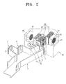
- FIG. 2 is a perspective view schematically illustrating an optical projection device, such as a projector or a projection displaying device, in accordance with another exemplary embodiment of the present invention, to which the heat radiating apparatus of FIG. 1 is applied.
- an optical projection device such as a projector or a projection displaying device
- the optical projection device in accordance with another exemplary embodiment of the present invention includes three LED illumination systems 1 each using an LED 2 as a light source, and a heat radiating apparatus to radiate a heat generated from the LED 2.
- the radiating apparatus includes a cooling fluid circulating unit 10, a heat exchanging unit 20, a fan unit 30, and a housing 40.
- a cooling fluid circulating unit 10 a heat exchanging unit 20
- a fan unit 30 a fan unit 30
- housing 40 a housing 40.
- the housing 40 is configured, so that it receives the cooling fluid circulating unit 10, the heat exchanging unit 20, and the fan unit 30 therein.
- the housing 40 has an air inlet 41 and an air outlet 42 formed at opposite sidewalls, respectively.
- a suction fan 31 for drawing in air is disposed at the air inlet 41, and a discharging fan 32 for discharging air is disposed at the air outlet 42.
- the suction fan 31 and the discharging fan 32 constitute the fan unit 30.
- a heat generated from the LED 2 is transmitted to the heat conductor 5 through the PCB 3, and then radiated to the radiating plate 11.
- the heat radiated to the radiating plate 11 is cooled by a cooling fluid, which circulates through the circulating piping 12 connected to the cooling fluid circulating lines in the radiating plate 11. While passing by the LED 2, the cooling fluid is heated, so that a temperature thereof is increased.
- the heated cooling fluid is moved to the heat exchanging unit 20 through the circulating piping 12. As the heated cooling fluid is moved to the heat exchanging unit 20, it radiates an internal heat to the outside through the plurality of radiating fins 20a, so that the temperature thereof is lowered. And then, the cooling fluid in which the temperature is lowered is again circulated via the LED 2 by the pump 13. As a result, the heat generated from the LED 2 can be effectively radiated.
- the heat radiating apparatus in accordance with the exemplary embodiment of the present invention effectively radiates the heat generated from the LED 2 by using the cooling fluid. Accordingly, a predetermined lifespan and a stable operation of the LED 2 can be guaranteed.
- the heat radiating apparatus in accordance with the exemplary embodiment of the present invention induces the flow of the external air to the radiating fins 20a with the fan unit 30. Accordingly, the heat exchange of the cooling fluid can be maximized.
- the heat radiating apparatus further includes the housing 40 to receive the cooling fluid circulating unit 10, the heat exchanging unit 20 and the like. Accordingly, the heat, which is radiated through the cooling fluid circulating unit 10, the heat exchanging unit 20 and the like, is blocked by the housing 40, so that the entry of the heat into an internal unit 7 including the LED illumination systems 1 vulnerable to heat is prevented, thereby preventing a temperature of the internal unit 7 from being increased.
- the heat radiating apparatus and the optical projection device having the same can effectively cool and radiate the heat generated from the optical projection device using the LED as a light source.
- the heat radiating apparatus and the optical projection device having the same can prevent the entry of heat generated from the heat radiating apparatus and/or the LED into the internal unit of the optical projection device, and thereby prevent the temperature of the internal unit from being increased.
Landscapes
- Health & Medical Sciences (AREA)
- Public Health (AREA)
- Life Sciences & Earth Sciences (AREA)
- Veterinary Medicine (AREA)
- General Health & Medical Sciences (AREA)
- Animal Behavior & Ethology (AREA)
- Physical Education & Sports Medicine (AREA)
- Rehabilitation Therapy (AREA)
- Pain & Pain Management (AREA)
- Epidemiology (AREA)
- Engineering & Computer Science (AREA)
- General Engineering & Computer Science (AREA)
- Biomedical Technology (AREA)
- Heart & Thoracic Surgery (AREA)
- Vascular Medicine (AREA)
- Projection Apparatus (AREA)
Applications Claiming Priority (1)
| Application Number | Priority Date | Filing Date | Title |
|---|---|---|---|
| KR1020060021357A KR20070091792A (ko) | 2006-03-07 | 2006-03-07 | 방열장치 및 이를 채용한 광학투사장치 |
Publications (1)
| Publication Number | Publication Date |
|---|---|
| EP1833287A2 true EP1833287A2 (de) | 2007-09-12 |
Family
ID=38229667
Family Applications (1)
| Application Number | Title | Priority Date | Filing Date |
|---|---|---|---|
| EP06077115A Pending EP1833287A2 (de) | 2006-03-07 | 2006-11-27 | Wärmeabfuhranordnung und optisches Projektionsgerät damit |
Country Status (4)
| Country | Link |
|---|---|
| US (1) | US20070211477A1 (de) |
| EP (1) | EP1833287A2 (de) |
| KR (1) | KR20070091792A (de) |
| CN (1) | CN101035424A (de) |
Cited By (2)
| Publication number | Priority date | Publication date | Assignee | Title |
|---|---|---|---|---|
| EP2256404A1 (de) * | 2009-05-25 | 2010-12-01 | Zumtobel Lighting GmbH | Anordnung zur Lichtabgabe mit Leuchtelementen |
| EP2753876B1 (de) * | 2011-09-05 | 2019-11-06 | Robe Lighting s.r.o. | Verbessertes kühlsystem für led-leuchte |
Families Citing this family (18)
| Publication number | Priority date | Publication date | Assignee | Title |
|---|---|---|---|---|
| TW200725156A (en) * | 2005-12-21 | 2007-07-01 | Premier Image Technology Corp | Portable projector with heat dissipating system |
| US8410402B2 (en) * | 2006-08-28 | 2013-04-02 | Dialight Corporation | Method and apparatus for using light emitting diodes for removing moisture |
| US7914152B2 (en) | 2008-02-01 | 2011-03-29 | Fu Zhun Precision Industry (Shen Zhen) Co., Ltd. | Portable projector using an LED and related heat dissipation system |
| GB2465493B (en) * | 2008-11-25 | 2011-07-27 | Stanley Electric Co Ltd | Liquid-cooled LED lighting device |
| CN101771127B (zh) * | 2008-12-30 | 2013-03-13 | 中国科学院理化技术研究所 | 带有液体金属散热热沉的led发光模块 |
| KR101043656B1 (ko) * | 2009-06-12 | 2011-06-22 | 한국기계연구원 | 고출력 엘이디의 방열을 위한 액체냉각장치 |
| CN101963743B (zh) * | 2009-07-24 | 2011-12-14 | 鸿富锦精密工业(深圳)有限公司 | 投影机 |
| KR100953088B1 (ko) * | 2009-08-04 | 2010-04-19 | (주)케이에프유 | 발광다이오드를 이용한 온풍기 |
| CN101699162B (zh) * | 2009-11-05 | 2012-07-11 | 深圳雅图数字视频技术有限公司 | 投影机灯泡散热系统及采用该系统的投影装置 |
| US8864335B2 (en) * | 2010-01-25 | 2014-10-21 | Sharp Kabushiki Kaisha | Illuminating device, display device, and television receiving device |
| CN103953907A (zh) * | 2014-05-19 | 2014-07-30 | 北京格林美芯科技发展有限公司 | 一种led液冷散热系统及大功率led聚光灯 |
| CN105030253A (zh) * | 2015-06-29 | 2015-11-11 | 武汉一海数字工程有限公司 | 一种多波长乳腺诊断光源 |
| JP6680551B2 (ja) * | 2016-02-05 | 2020-04-15 | マクセル株式会社 | 投射型映像表示装置 |
| CN107680947A (zh) * | 2017-08-11 | 2018-02-09 | 江苏南通申通机械有限公司 | 一种相变冷却系统 |
| CN209373333U (zh) * | 2018-09-07 | 2019-09-10 | 中强光电股份有限公司 | 投影装置 |
| US11047560B2 (en) * | 2019-05-29 | 2021-06-29 | Nbcuniversal Media, Llc | Light emitting diode cooling systems and methods |
| CN110244504B (zh) * | 2019-06-17 | 2021-02-26 | 宁波市法诺工业产品设计有限公司 | 一种多功能教育投影仪装置 |
| CN110794642B (zh) * | 2019-09-25 | 2021-02-12 | 深圳市火乐科技发展有限公司 | 投影仪 |
Family Cites Families (9)
| Publication number | Priority date | Publication date | Assignee | Title |
|---|---|---|---|---|
| US6517221B1 (en) * | 1999-06-18 | 2003-02-11 | Ciena Corporation | Heat pipe heat sink for cooling a laser diode |
| TW524319U (en) * | 2002-03-22 | 2003-03-11 | Coretronic Corp | Heat dissipating structure of projector |
| AU2003296485A1 (en) * | 2002-12-11 | 2004-06-30 | Charles Bolta | Light emitting diode (l.e.d.) lighting fixtures with emergency back-up and scotopic enhancement |
| US20040264192A1 (en) * | 2003-05-06 | 2004-12-30 | Seiko Epson Corporation | Light source apparatus, method of manufacture therefor, and projection-type display apparatus |
| US7309145B2 (en) * | 2004-01-13 | 2007-12-18 | Seiko Epson Corporation | Light source apparatus and projection display apparatus |
| US7140753B2 (en) * | 2004-08-11 | 2006-11-28 | Harvatek Corporation | Water-cooling heat dissipation device adopted for modulized LEDs |
| CN100468709C (zh) * | 2005-03-18 | 2009-03-11 | 鸿富锦精密工业(深圳)有限公司 | 发光模组及其光源装置 |
| TWM313260U (en) * | 2006-08-30 | 2007-06-01 | Yu-Nung Shen | Light source device for projector |
| US20080062694A1 (en) * | 2006-09-07 | 2008-03-13 | Foxconn Technology Co., Ltd. | Heat dissipation device for light emitting diode module |
-
2006
- 2006-03-07 KR KR1020060021357A patent/KR20070091792A/ko not_active Withdrawn
- 2006-10-06 US US11/543,789 patent/US20070211477A1/en not_active Abandoned
- 2006-11-27 EP EP06077115A patent/EP1833287A2/de active Pending
- 2006-11-28 CN CNA2006101604983A patent/CN101035424A/zh active Pending
Cited By (2)
| Publication number | Priority date | Publication date | Assignee | Title |
|---|---|---|---|---|
| EP2256404A1 (de) * | 2009-05-25 | 2010-12-01 | Zumtobel Lighting GmbH | Anordnung zur Lichtabgabe mit Leuchtelementen |
| EP2753876B1 (de) * | 2011-09-05 | 2019-11-06 | Robe Lighting s.r.o. | Verbessertes kühlsystem für led-leuchte |
Also Published As
| Publication number | Publication date |
|---|---|
| CN101035424A (zh) | 2007-09-12 |
| KR20070091792A (ko) | 2007-09-12 |
| US20070211477A1 (en) | 2007-09-13 |
Similar Documents
| Publication | Publication Date | Title |
|---|---|---|
| EP1833287A2 (de) | Wärmeabfuhranordnung und optisches Projektionsgerät damit | |
| EP3593606B1 (de) | Anzeigevorrichtung | |
| US7830660B2 (en) | Cooling unit and display apparatus having the same | |
| CN101852976B (zh) | 投射设备 | |
| US20060245214A1 (en) | Liquid crystal display having heat dissipation device | |
| US8246171B2 (en) | Cooling device and projector using the same | |
| KR102400990B1 (ko) | 열 관리 시스템 | |
| US8035968B2 (en) | Display apparatus | |
| US9837789B2 (en) | Air-cooled laser device having L-shaped heat-transfer member with radiating fins | |
| CN206674407U (zh) | 散热系统和电子设备 | |
| US8944638B2 (en) | Light source device and projection type display device including the same | |
| JP2009049010A (ja) | パワーled照明装置 | |
| WO2010007821A1 (ja) | 電子装置及び画像表示装置、ならびに電子装置の冷却方法 | |
| CN101063798B (zh) | 投射型视频显示装置 | |
| US20160254643A1 (en) | Air-cooled laser device having heat-transfer member with heat radiating fins | |
| CN100498512C (zh) | 投射型视频显示装置 | |
| JP5384990B2 (ja) | 水冷式led照明装置 | |
| KR20170126308A (ko) | 냉매를 이용한 발광램프용 방열구조 | |
| TWI437950B (zh) | 用於熱控制電子顯示器的系統和方法 | |
| JP5384991B2 (ja) | 水冷式led照明装置 | |
| US12153480B2 (en) | Computing devices with integrated and isolated liquid cooling | |
| JP2008268616A (ja) | 冷却装置を備えた投写型表示機器 | |
| JP2013229123A (ja) | 強制冷却式led照明装置 | |
| KR100688979B1 (ko) | 백라이트유닛 | |
| JP2013229119A (ja) | 強制冷却式led照明装置 |
Legal Events
| Date | Code | Title | Description |
|---|---|---|---|
| PUAI | Public reference made under article 153(3) epc to a published international application that has entered the european phase |
Free format text: ORIGINAL CODE: 0009012 |
|
| AK | Designated contracting states |
Kind code of ref document: A2 Designated state(s): AT BE BG CH CY CZ DE DK EE ES FI FR GB GR HU IE IS IT LI LT LU LV MC NL PL PT RO SE SI SK TR |
|
| AX | Request for extension of the european patent |
Extension state: AL BA HR MK YU |
|
| D18D | Application deemed to be withdrawn (deleted) | ||
| STAA | Information on the status of an ep patent application or granted ep patent |
Free format text: STATUS: THE APPLICATION IS DEEMED TO BE WITHDRAWN |
|
| 18D | Application deemed to be withdrawn |
Effective date: 20090531 |