EP1833427B1 - Modulares intervertebrales implantat - Google Patents
Modulares intervertebrales implantat Download PDFInfo
- Publication number
- EP1833427B1 EP1833427B1 EP05817955A EP05817955A EP1833427B1 EP 1833427 B1 EP1833427 B1 EP 1833427B1 EP 05817955 A EP05817955 A EP 05817955A EP 05817955 A EP05817955 A EP 05817955A EP 1833427 B1 EP1833427 B1 EP 1833427B1
- Authority
- EP
- European Patent Office
- Prior art keywords
- component
- intervertebral implant
- components
- centre
- radius
- Prior art date
- Legal status (The legal status is an assumption and is not a legal conclusion. Google has not performed a legal analysis and makes no representation as to the accuracy of the status listed.)
- Expired - Lifetime
Links
Images



Classifications
-
- A—HUMAN NECESSITIES
- A61—MEDICAL OR VETERINARY SCIENCE; HYGIENE
- A61F—FILTERS IMPLANTABLE INTO BLOOD VESSELS; PROSTHESES; DEVICES PROVIDING PATENCY TO, OR PREVENTING COLLAPSING OF, TUBULAR STRUCTURES OF THE BODY, e.g. STENTS; ORTHOPAEDIC, NURSING OR CONTRACEPTIVE DEVICES; FOMENTATION; TREATMENT OR PROTECTION OF EYES OR EARS; BANDAGES, DRESSINGS OR ABSORBENT PADS; FIRST-AID KITS
- A61F2/00—Filters implantable into blood vessels; Prostheses, i.e. artificial substitutes or replacements for parts of the body; Appliances for connecting them with the body; Devices providing patency to, or preventing collapsing of, tubular structures of the body, e.g. stents
- A61F2/02—Prostheses implantable into the body
- A61F2/30—Joints
- A61F2/44—Joints for the spine, e.g. vertebrae, spinal discs
-
- A—HUMAN NECESSITIES
- A61—MEDICAL OR VETERINARY SCIENCE; HYGIENE
- A61F—FILTERS IMPLANTABLE INTO BLOOD VESSELS; PROSTHESES; DEVICES PROVIDING PATENCY TO, OR PREVENTING COLLAPSING OF, TUBULAR STRUCTURES OF THE BODY, e.g. STENTS; ORTHOPAEDIC, NURSING OR CONTRACEPTIVE DEVICES; FOMENTATION; TREATMENT OR PROTECTION OF EYES OR EARS; BANDAGES, DRESSINGS OR ABSORBENT PADS; FIRST-AID KITS
- A61F2/00—Filters implantable into blood vessels; Prostheses, i.e. artificial substitutes or replacements for parts of the body; Appliances for connecting them with the body; Devices providing patency to, or preventing collapsing of, tubular structures of the body, e.g. stents
- A61F2/02—Prostheses implantable into the body
- A61F2/30—Joints
- A61F2/44—Joints for the spine, e.g. vertebrae, spinal discs
- A61F2/442—Intervertebral or spinal discs, e.g. resilient
- A61F2/4425—Intervertebral or spinal discs, e.g. resilient made of articulated components
-
- A—HUMAN NECESSITIES
- A61—MEDICAL OR VETERINARY SCIENCE; HYGIENE
- A61F—FILTERS IMPLANTABLE INTO BLOOD VESSELS; PROSTHESES; DEVICES PROVIDING PATENCY TO, OR PREVENTING COLLAPSING OF, TUBULAR STRUCTURES OF THE BODY, e.g. STENTS; ORTHOPAEDIC, NURSING OR CONTRACEPTIVE DEVICES; FOMENTATION; TREATMENT OR PROTECTION OF EYES OR EARS; BANDAGES, DRESSINGS OR ABSORBENT PADS; FIRST-AID KITS
- A61F2/00—Filters implantable into blood vessels; Prostheses, i.e. artificial substitutes or replacements for parts of the body; Appliances for connecting them with the body; Devices providing patency to, or preventing collapsing of, tubular structures of the body, e.g. stents
- A61F2/02—Prostheses implantable into the body
- A61F2/30—Joints
- A61F2002/30001—Additional features of subject-matter classified in A61F2/28, A61F2/30 and subgroups thereof
- A61F2002/30316—The prosthesis having different structural features at different locations within the same prosthesis; Connections between prosthetic parts; Special structural features of bone or joint prostheses not otherwise provided for
- A61F2002/30535—Special structural features of bone or joint prostheses not otherwise provided for
- A61F2002/30604—Special structural features of bone or joint prostheses not otherwise provided for modular
- A61F2002/30616—Sets comprising a plurality of prosthetic parts of different sizes or orientations
-
- A—HUMAN NECESSITIES
- A61—MEDICAL OR VETERINARY SCIENCE; HYGIENE
- A61F—FILTERS IMPLANTABLE INTO BLOOD VESSELS; PROSTHESES; DEVICES PROVIDING PATENCY TO, OR PREVENTING COLLAPSING OF, TUBULAR STRUCTURES OF THE BODY, e.g. STENTS; ORTHOPAEDIC, NURSING OR CONTRACEPTIVE DEVICES; FOMENTATION; TREATMENT OR PROTECTION OF EYES OR EARS; BANDAGES, DRESSINGS OR ABSORBENT PADS; FIRST-AID KITS
- A61F2/00—Filters implantable into blood vessels; Prostheses, i.e. artificial substitutes or replacements for parts of the body; Appliances for connecting them with the body; Devices providing patency to, or preventing collapsing of, tubular structures of the body, e.g. stents
- A61F2/02—Prostheses implantable into the body
- A61F2/30—Joints
- A61F2002/30001—Additional features of subject-matter classified in A61F2/28, A61F2/30 and subgroups thereof
- A61F2002/30621—Features concerning the anatomical functioning or articulation of the prosthetic joint
- A61F2002/30649—Ball-and-socket joints
-
- A—HUMAN NECESSITIES
- A61—MEDICAL OR VETERINARY SCIENCE; HYGIENE
- A61F—FILTERS IMPLANTABLE INTO BLOOD VESSELS; PROSTHESES; DEVICES PROVIDING PATENCY TO, OR PREVENTING COLLAPSING OF, TUBULAR STRUCTURES OF THE BODY, e.g. STENTS; ORTHOPAEDIC, NURSING OR CONTRACEPTIVE DEVICES; FOMENTATION; TREATMENT OR PROTECTION OF EYES OR EARS; BANDAGES, DRESSINGS OR ABSORBENT PADS; FIRST-AID KITS
- A61F2/00—Filters implantable into blood vessels; Prostheses, i.e. artificial substitutes or replacements for parts of the body; Appliances for connecting them with the body; Devices providing patency to, or preventing collapsing of, tubular structures of the body, e.g. stents
- A61F2/02—Prostheses implantable into the body
- A61F2/30—Joints
- A61F2/30767—Special external or bone-contacting surface, e.g. coating for improving bone ingrowth
- A61F2/30771—Special external or bone-contacting surface, e.g. coating for improving bone ingrowth applied in original prostheses, e.g. holes or grooves
- A61F2002/30841—Sharp anchoring protrusions for impaction into the bone, e.g. sharp pins, spikes
- A61F2002/30843—Pyramidally-shaped
-
- A—HUMAN NECESSITIES
- A61—MEDICAL OR VETERINARY SCIENCE; HYGIENE
- A61F—FILTERS IMPLANTABLE INTO BLOOD VESSELS; PROSTHESES; DEVICES PROVIDING PATENCY TO, OR PREVENTING COLLAPSING OF, TUBULAR STRUCTURES OF THE BODY, e.g. STENTS; ORTHOPAEDIC, NURSING OR CONTRACEPTIVE DEVICES; FOMENTATION; TREATMENT OR PROTECTION OF EYES OR EARS; BANDAGES, DRESSINGS OR ABSORBENT PADS; FIRST-AID KITS
- A61F2310/00—Prostheses classified in A61F2/28 or A61F2/30 - A61F2/44 being constructed from or coated with a particular material
- A61F2310/00005—The prosthesis being constructed from a particular material
- A61F2310/00011—Metals or alloys
-
- A—HUMAN NECESSITIES
- A61—MEDICAL OR VETERINARY SCIENCE; HYGIENE
- A61F—FILTERS IMPLANTABLE INTO BLOOD VESSELS; PROSTHESES; DEVICES PROVIDING PATENCY TO, OR PREVENTING COLLAPSING OF, TUBULAR STRUCTURES OF THE BODY, e.g. STENTS; ORTHOPAEDIC, NURSING OR CONTRACEPTIVE DEVICES; FOMENTATION; TREATMENT OR PROTECTION OF EYES OR EARS; BANDAGES, DRESSINGS OR ABSORBENT PADS; FIRST-AID KITS
- A61F2310/00—Prostheses classified in A61F2/28 or A61F2/30 - A61F2/44 being constructed from or coated with a particular material
- A61F2310/00389—The prosthesis being coated or covered with a particular material
- A61F2310/00395—Coating or prosthesis-covering structure made of metals or of alloys
- A61F2310/00407—Coating made of titanium or of Ti-based alloys
-
- A—HUMAN NECESSITIES
- A61—MEDICAL OR VETERINARY SCIENCE; HYGIENE
- A61F—FILTERS IMPLANTABLE INTO BLOOD VESSELS; PROSTHESES; DEVICES PROVIDING PATENCY TO, OR PREVENTING COLLAPSING OF, TUBULAR STRUCTURES OF THE BODY, e.g. STENTS; ORTHOPAEDIC, NURSING OR CONTRACEPTIVE DEVICES; FOMENTATION; TREATMENT OR PROTECTION OF EYES OR EARS; BANDAGES, DRESSINGS OR ABSORBENT PADS; FIRST-AID KITS
- A61F2310/00—Prostheses classified in A61F2/28 or A61F2/30 - A61F2/44 being constructed from or coated with a particular material
- A61F2310/00389—The prosthesis being coated or covered with a particular material
- A61F2310/00574—Coating or prosthesis-covering structure made of carbon, e.g. of pyrocarbon
- A61F2310/0058—Coating made of diamond or of diamond-like carbon DLC
-
- A—HUMAN NECESSITIES
- A61—MEDICAL OR VETERINARY SCIENCE; HYGIENE
- A61F—FILTERS IMPLANTABLE INTO BLOOD VESSELS; PROSTHESES; DEVICES PROVIDING PATENCY TO, OR PREVENTING COLLAPSING OF, TUBULAR STRUCTURES OF THE BODY, e.g. STENTS; ORTHOPAEDIC, NURSING OR CONTRACEPTIVE DEVICES; FOMENTATION; TREATMENT OR PROTECTION OF EYES OR EARS; BANDAGES, DRESSINGS OR ABSORBENT PADS; FIRST-AID KITS
- A61F2310/00—Prostheses classified in A61F2/28 or A61F2/30 - A61F2/44 being constructed from or coated with a particular material
- A61F2310/00389—The prosthesis being coated or covered with a particular material
- A61F2310/00592—Coating or prosthesis-covering structure made of ceramics or of ceramic-like compounds
- A61F2310/0073—Coating or prosthesis-covering structure made of compounds based on metal carbides
- A61F2310/00748—Coating made of titanium carbide
-
- A—HUMAN NECESSITIES
- A61—MEDICAL OR VETERINARY SCIENCE; HYGIENE
- A61F—FILTERS IMPLANTABLE INTO BLOOD VESSELS; PROSTHESES; DEVICES PROVIDING PATENCY TO, OR PREVENTING COLLAPSING OF, TUBULAR STRUCTURES OF THE BODY, e.g. STENTS; ORTHOPAEDIC, NURSING OR CONTRACEPTIVE DEVICES; FOMENTATION; TREATMENT OR PROTECTION OF EYES OR EARS; BANDAGES, DRESSINGS OR ABSORBENT PADS; FIRST-AID KITS
- A61F2310/00—Prostheses classified in A61F2/28 or A61F2/30 - A61F2/44 being constructed from or coated with a particular material
- A61F2310/00389—The prosthesis being coated or covered with a particular material
- A61F2310/00592—Coating or prosthesis-covering structure made of ceramics or of ceramic-like compounds
- A61F2310/00796—Coating or prosthesis-covering structure made of a phosphorus-containing compound, e.g. hydroxy(l)apatite
Definitions
- the invention relates to an intervertebral implant, particularly an artificial intervertebral disc.
- Implants or prostheses are inserted into the intervertebral space of two adjoining vertebral bodies after removal of an affected natural intervertebral disc or an affected nucleus pulposus of an intervertebral disc. It is the object of the implantation of such implants to regain the natural qualities as well as possible, i.e. particularly the original height of the intervertebral disc and consequently the original distance between the two adjoining vertebral bodies. Furthermore, motions of the adjoining vertebral bodies relative to each other shall be permitted in their natural quality without being impeded. For this reason a conservation of the possibility of motion in case of forward/backward bending, i.e.
- Such an intervertebral implant is known from US 5,314,477 MARNAY.
- This known implant comprises two plates being connected by means of a ball-joint. Since only one size of the implant as well as only one value for the radius of the articulation surfaces is provided the centre of rotation of the implant as well as its kinematics are predefined so that the surgeon may not individually adapt these qualities to the needs, respectively the anatomy of the patient. Furthermore, these implants are not configured to adapt the centre of rotation of the spherical cap to the individual anatomical requirements.
- FR-A-2 718 635 discloses an intervertebral implant from which the invention as defined in claim 1 differs in that the first component is selected from a set of M ⁇ 2 first components with different heights H1.
- an intervertebral implant permitting an optimal moveability of the adjacent vertebral bodies as well as to take into consideration the individual physiology of the patient to be treated.
- the present invention relates to a modular intervertebral implant and more particularly to an artificial intervertebral disk comprising two components being mutually connectable in a ball-joint like manner.
- the first and second components are provided with an apposition area each, said apposition area being apt for abutment to the end plates of the adjoining vertebral bodies.
- said first and second components are provided with a concave, respectively a convex spherical articulation surface having the same radius R.
- the first and second component have a maximum height H 1 , respectively H 2 , such that a maximum overall height H ⁇ (H 1 + H 2 ) results for the assembled intervertebral implant.
- the intervertebral implant is provided with a centre of rotation RZ which has a shortest distance A to the second apposition area, said shortest distance A being equal to the absolute value of (H 2 - R), and said first and second components are selected from a first kit of at least M ⁇ 2 first components having different heights H 1 , respectively from a second kit of at least N ⁇ 2 second components (4) having different heights H 2 , such permitting a selection of the distance A of the centre of rotation RZ through a selection of the radius R and the maximum height H 2 of the second component.
- the intervertebral implant according to the invention is implantable into the intervertebral space by means of one or two posterior approaches because the implant is configured in two-piece form such that the two components are implantable mutually independently into the intervertebral space through the two separate approaches.
- the similar implantation procedure is anteriorly applicable, particularly in the higher lumbar as well as in the thoracolumbar section.
- the anatomical conditions do not allow an insertion from strict anterior, since the aorta and the vena cava impede the approach. In this case the ventral structure of the annulus fibrosus as well as the anterior longitudinal ligament are being kept intact, as well.
- the two kits of first and second components of the intervertebral implant are configured such that the overall height H is constant for any combination of a first component with a second component.
- all components of the two kits are provided with the same radius R.
- the advantages of this embodiment are that the coincidence of the radii R of the spherical caps enables the bearing to act as a slideable surface bearing for each arbitrary combination of a first and a second component, causing less abrasion due to the decreased surface pressure compared to a line contact bearing as in case of different radii R.
- first components of the first kit are provided with radii R of the same length.
- first components of the first kit are provided with radii R of different length.
- the advantages of this embodiment are that the position of the centre of rotation on the central axis is adjustable solely through a variation of the radius R independently of the height of the two components.
- the distance A of the centre of rotation to the second apposition area is about 30% of the maximum overall height.
- the distance A of the centre of rotation RZ to the second apposition area is about 600% of the maximum overall height H.
- the centre of rotation RZ is located inside the second component and the difference (H 2 - R) has a positive value.
- the advantages of this embodiment are essentially to be seen in the fact that such a configuration results in a small radius of the spherical cap, consequently resulting in a relatively small translational part of motion between the two components, i.e. a small mutual displacement transverse to the central axis in case of a mutual rotation of the two components about the centre of rotation RZ.
- the articulation surfaces are taken care of since no compression arises during flexion- or extension motions.
- the distance A inside the second component is minimum 0,5 mm, respectively maximum 5 mm.
- the centre of rotation RZ is located outside of the second component and the difference (H 2 - R) has a negative value.
- the advantages of this embodiment essentially are the resulting relatively large radii of the spherical cap consequently resulting in a relatively high translational part of motion between the two components, i.e. a high relative displacement transverse to the central axis.
- the articulation surfaces are taken care of since no compression arises during flexion- or extension motions.
- the distance A outside of the second component is minimum 1 mm, respectively maximum 95 mm.
- the first component is configured as a plate like base body with a recessed concave spherical articulation surface and the second component is configured as a plate like base body with a protruding spherical segment.
- the radius of the spherical segment of the second component is between 3 mm and 100 mm, preferably between 4 mm and 20 mm.
- the second component consists of a metal - plastic material combination.
- convex spherical articulation surface is coated with titanium carbide or amorphous carbon (ADLC).
- ADLC amorphous carbon
- the apposition areas are coated with titanium.
- the apposition areas are convexely shaped.
- the apposition areas are provided with projections, which comprise at least one wedge like rip being symmetrical to the center plane of the implant and which is standing on the respective apposition area parallel to a straight line in the center plane.
- the projections may comprise saw-tooth like indentations which are arranged symmetrically to the center plane.
- the volume of one projection may be between 0,12 mm 3 and 1,4 mm 3 .
- the projections may be at least partially coated with hydroxyl apatite or with a bi-phase hydroxyl apatite- calcium phosphate mixture.
- the two components have a mutually facing intermediate surface each whereby these intermediate surfaces are tiltable relative to each other within a range of 0° to 12°.
- the two components have a centre of gravity each, and wherein upon rotation of the two components relative to each other said centres of gravity perform a translation T relative to each other measured perpendicularly to the central axis and being dependent on the radius R, whereby the translation T is in the range of 0,5 mm to 12,0 mm.
- the embodiment shown in fig. 1 essentially comprises an intervertebral implant 1 with a central axis 2, said intervertebral implant 1 having two components 3;4, whereby the first component 3 consists of a one-piece plate comprising a first apposition area 5 and oppositely arranged an intermediate surface 7 with a concave spherical articulation surface 9.
- the second component 4 essentially consists of a plate, comprising a second apposition area 6 and oppositely arranged an intermediate surface 8, said second component 4 further comprising a spherical segment 11 being placed upon its intermediate surface 8.
- the spherical segment 11 is provided with a convex spherical articulation surface 10 apt as a bearing surface permitting slideable motion relative to the concave spherical articulation surface 10.
- the mutual tilting of the two components 3;4 around the centre of rotation RZ which is situated on the central axis 2 is limited by the fact that the mutually facing intermediate surfaces 7;8 come at rest at each other if the maximum angle of tilting is achieved.
- the two apposition areas 5;6 are convexely curved in a manner that an optimal fit to the end plates of the adjoining intervertebral bodies is achieved.
- the joint connection between the two components 3;4 further permits a free mutual rotation of the two components 3;4 about the central axis 2.
- the spherical segment 11 located between the two components 3;4 together with the concave spherical articulation surface 9 form an articulating connection, whereby the radii R of curvature of the concave spherical articulation surface 9 and the convex spherical articulation surface 10 are equal to each other.
- the intervertebral implant has a maximum overall height H, whereby the first component 3 has a maximum height H 1 measured parallel to the central axis 2 and the second component 4 has a maximum height H 2 measured parallel to the central axis 2 as well.
- the shortest distance A extends coaxially to the central axis 2 and extends between the centre of rotation RZ located on the central axis 2 and the second apposition area 6.
- a series of three cross-sections of the intervertebral implant 1 illustrated in Fig. 2 shows three different combinations of first and second components 3;4 having different maximum heights H 1 and H 2 each, whereby the length of the radius R of the spherical segments 11 remains unchanged.
- the shortest distance A measured coaxially to the central axis 2 between the centre of rotation RZ and the second apposition area 6 varies for the different maximum heights H 1 and H 2 of the two components 3;4, whereby the maximum overall height H remains constant.
- the maximum height H 1 of the first component 3 increases from left to right in the series shown here, while the maximum height H 2 of the second component 4 simultaneously decreases correspondingly so that the overall height H remains constant.
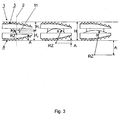
- the series of three cross-sections of the intervertebral implant 1 illustrated in Fig. 3 shows three different combinations of first and second components 3;4 having different lengths of the radius R and of the shortest distances A.
- the maximum height H 2 of the second component 4 decreases from left to right, whereby the length of the radius R increases and whereby the centre of rotation RZ simultaneously moves along the central axis 2 in such manner that the distance A increases.
- the dislocation of the centre of rotation RZ the sliding motion of the concave spherical articulation surface 9 on the convex spherical articulation surface 10 and hence, the motion of the two adjacent vertebral bodies, is being influenced.
- the series of three cross-sections of the intervertebral implant 1 illustrated in Fig. 4 shows three different combinations of first and second components 3;4 having different lengths of the radius R and different ranges of the translational motion T, whereby the translational motion T is defined through the displacement of the centres of gravity of the two components 3;4 measured perpendicularly to the central axis 2 due to a mutual rotation of the two components 3;4.
- the maximum height H 2 of the second component 4 decreases from left to right, whereby the length of the radius R increases.
- the apposition areas 5;6 are provided with macroscopic structures, which are configured as protrusions 13, for example as pyramid like protrusions.
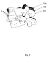
- Fig. 5 schematically shows the series of X-ray images of the portion of the vertebra to be treated acquired during the preoperative study, whereby the point L indicates an anatomical land mark at the upper vertebral body.
- the different positions of the anatomical land mark L in case of a neutral position 10, an extension 300 and a flexion 200 of the vertebra define three points, said three points define a circle which is subsequently used in order to determine the centre of rotation RZ and the spherical segment 11.
- the basis for the determination of the centre of rotation RZ and of the radius R of the spherical segment 11 is the fact that a circle is defined by three points, said circle being defined through the geometrical construction of a circumcircle of a triangle ABC.
- the circumcentre of the required circle corresponds to the centre of rotation RZ and is defined through the point of intersection of the three perpendicular bisector of the sides AB, BC and AC of the triangle.
- the preoperative planning including the above determination of the centre of rotation RZ and of the radius R is then performed as follows:
- the superior end plate of the lower vertebral body serves as a basis while the at the upper vertebral body the anatomical landmarks L are defined in order to reconstruct the motion of the upper vertebral- body relative to the lower vertebral body.
- the motion of the upper vertebral body is defined through three points and as described above the spherical element 11 corresponding to the natural spherical cap of the intervertebral disc may be determined.
- the centre of rotation RZ of the spherical element 11 of the intervertebral implant coincides with the centre of the natural spherical cap therewith permitting the supporting quality of the intervertebral implant 1.
- the centre of rotation RZ of the intervertebral implant 1 coincides with the circumcentre defined by means of the study of motion.
Landscapes
- Health & Medical Sciences (AREA)
- Engineering & Computer Science (AREA)
- Biomedical Technology (AREA)
- Orthopedic Medicine & Surgery (AREA)
- Neurology (AREA)
- Heart & Thoracic Surgery (AREA)
- Oral & Maxillofacial Surgery (AREA)
- Transplantation (AREA)
- Cardiology (AREA)
- Vascular Medicine (AREA)
- Life Sciences & Earth Sciences (AREA)
- Animal Behavior & Ethology (AREA)
- General Health & Medical Sciences (AREA)
- Public Health (AREA)
- Veterinary Medicine (AREA)
- Prostheses (AREA)
- Materials For Medical Uses (AREA)
Claims (18)
- Modulares Zwischenwirbelimplantat (1), insbesondere künstliche Bandscheibe, mit einer Zentralachse (2), umfassend ein erstes und ein zweites Teil (3,4), welche kugelgelenkartig miteinander verbindbar sind, wobeiA) das erste Teil (3) eine Appositionsfläche (5) aufweist, welche zur Anlage an die Endplatte eines daran angrenzenden Wirbelkörpers geeignet ist und eine konkave sphärische Gelenkfläche (9) mit dem Radius R aufweist;B) das zweite Teil (4) eine Appositionsfläche (6) aufweist, welche zur Anlage an die Endplatte eines daran angrenzenden Wirbelkörpers geeignet ist und eine konvexe sphärische Gelenkfläche (10) mit dem gleichen Radius R wie die konkave sphärische Gelenkfläche (9) aufweist;C) das erste Teil (3) eine maximale Bauhöhe H1 und das zweite Teil (4) eine maximale Bauhöhe H2 aufweist, so dass sich eine maximale Gesamt-Bauhöhe H < (H1 + H2) des zusammengesetzten Zwischenwirbelimplantat (1) ergibt; undD) das Zwischenwirbelimplantat (1) ein Rotationszentrum RZ besitzt, welches einen kürzesten Abstand A von der zweiten Appositionsfläche (6) aufweist, welcher dem absoluten Betrag der Differenz von (H2 - R) entspricht, und wobeiE) das erste Teil (3) aus einem ersten Bausatz von mindestens M ≥ 2 ersten Teilen (3) mit unterschiedlicher maximaler Bauhöhe H1 ausgewählt ist; undF) das zweite Teil (4) aus einem zweiten Bausatz von mindestens N ≥ 2 zweiten Teilen (4) mit unterschiedlicher maximaler Bauhöhe H2 ausgewählt ist; so dassG) eine Auswahl des Abstands A des Rotationszentrums RZ des derart zusammengestellten Zwischenwirbelimplantates (1) ermöglicht wird.
- Zwischenwirbelimplantat (1) nach Anspruch 1, dadurch gekennzeichnet, dass die beiden Bausätze erster und zweiter Teile (3,4) derart ausgebildet sind, dass die Gesamt-Bauhöhe H für jede beliebige Kombination eines ersten Teils (3) mit einem zweiten Teil (4) konstant bleibt.
- Zwischenwirbelimplantat (1) nach Anspruch 1 oder 2, dadurch gekennzeichnet, dass sämtliche Teile (3,4) der beiden Bausätze den gleichen Radius R aufweisen.
- Zwischenwirbelimplantat (1) nach einem der Ansprüche 1 bis 3, dadurch gekennzeichnet, dass die konkaven sphärischen Gelenkflächen (9) der M ersten Teile (3) des ersten Bausatzes den gleichen Radius R aufweisen.
- Zwischenwirbelimplantat (1) nach einem der Ansprüche 1 bis 3, dadurch gekennzeichnet, dass die konkaven sphärischen Gelenkflächen (9) der M ersten Teile (3) des ersten Bausatzes unterschiedliche Radien R aufweisen.
- Zwischenwirbelimplantat (1) nach einem der Ansprüche 1 bis 5, dadurch gekennzeichnet, dass der Abstand A einen Betrag von mehr als 30 % der Gesamtbauhöhe H aufweist.
- Zwischenwirbelimplantat (1) nach einem der Ansprüche 1 bis 6, dadurch gekennzeichnet, dass der Abstand A einen Betrag von weniger als 600 % der Gesamtbauhöhe H aufweist.
- Zwischenwirbelimplantat (1) nach einem der Ansprüche 1 bis 7, dadurch gekennzeichnet, dass das Rotationszentrum RZ im Inneren des zweiten Teiles (4) liegt mit einem positiven Wert für die Differenz von (H2 - R).
- Zwischenwirbelimplantat (1) nach einem der Ansprüche 1 bis 8, dadurch gekennzeichnet, dass das Rotationszentrum RZ ausserhalb des zweiten Teiles (4) liegt mit einem negativen Wert für die Differenz (H2 - R).
- Zwischenwirbelimplantat (1) nach einem der Ansprüche 1 bis 9, dadurch gekennzeichnet, dass der Abstand A maximal 5 mm im Inneren des zweiten Teils (4) und maximal 95 mm ausserhalb des zweiten Teils (4) beträgt.
- Zwischenwirbelimplantat (1) nach einem der Ansprüche 1 bis 10, dadurch gekennzeichnet, dass der Abstand A minimal 0,5 mm im Inneren des zweiten Teils (4) beträgt.
- Zwischenwirbelimplantat (1) nach einem der Ansprüche 1 bis 10, dadurch gekennzeichnet, dass der Abstand A minimal 1 mm ausserhalb des zweiten Teils beträgt.
- Zwischenwirbelimplantat (1) nach einem der Ansprüche 1 bis 12, dadurch gekennzeichnet, dass das erste Teil (3) als plattenförmiger Grundkörper mit einer vertieften konkaven sphärischen Gelenkfläche (9) ausgebildet ist und das zweite Teil (4) als plattenförmiger Grundkörper mit einem vorstehenden Kugelsegment (11) ist.
- Zwischenwirbelimplantat (1) nach Anspruch 12, dadurch gekennzeichnet, dass der Radius R des Kugelsegments (11) des zweiten Teils (4) zwischen 3 mm und 100 mm beträgt.
- Zwischenwirbelimplantat (1) nach Anspruch 13, dadurch gekennzeichnet, dass der Radius R des Kugelsegments (11) des zweiten Teils (4) zwischen 4 mm und 20 mm beträgt.
- Zwischenwirbelimplantat (1) nach einem der Ansprüche 1 bis 15, dadurch gekennzeichnet, dass die konvexe sphärische Gelenkfläche (10) mit Titankarbid oder amorphem Kohlenstoff (ADLC) beschichtet ist.
- Zwischenwirbelimplantat (1) nach einem der Ansprüche 1 bis 16, dadurch gekennzeichnet, dass die zwei Teile (3;4) je eine gegenseitig benachbarte Oberfläche (7;8) aufweisen, und dass die Abkippung dieser zwei Oberflächen (7;8) relativ zueinander in einem Bereich zwischen 0° und 12° möglich ist.
- Zwischenwirbelimplantat (1) nach einem der Ansprüche 1 bis 17, dadurch gekennzeichnet, dass die zwei Teile (3;4) je einen Schwerpunkt besitzen, und dass bei Rotation der zwei Teile (3;4) relativ zueinander diese Schwerpunkte abhängig vom Radius R eine zur Zentralachse (2) senkrecht gemessene Translation T relativ zueinander ausführen, wobei die Translation T zwischen 0,5 mm und 12,0 mm beträgt.
Priority Applications (1)
| Application Number | Priority Date | Filing Date | Title |
|---|---|---|---|
| PL05817955T PL1833427T3 (pl) | 2004-12-28 | 2005-12-27 | Modułowy implant międzykręgowy |
Applications Claiming Priority (2)
| Application Number | Priority Date | Filing Date | Title |
|---|---|---|---|
| CH02161/04A CH697737B1 (de) | 2004-12-28 | 2004-12-28 | Bausatz zur Zusammenstellung eines Zwischenwirbelimplantates. |
| PCT/CH2005/000775 WO2006069463A1 (en) | 2004-12-28 | 2005-12-27 | Modular intervertebral implant |
Publications (2)
| Publication Number | Publication Date |
|---|---|
| EP1833427A1 EP1833427A1 (de) | 2007-09-19 |
| EP1833427B1 true EP1833427B1 (de) | 2010-01-20 |
Family
ID=36011069
Family Applications (1)
| Application Number | Title | Priority Date | Filing Date |
|---|---|---|---|
| EP05817955A Expired - Lifetime EP1833427B1 (de) | 2004-12-28 | 2005-12-27 | Modulares intervertebrales implantat |
Country Status (16)
| Country | Link |
|---|---|
| US (1) | US8721724B2 (de) |
| EP (1) | EP1833427B1 (de) |
| JP (1) | JP4778525B2 (de) |
| KR (1) | KR101321672B1 (de) |
| CN (1) | CN101087572B (de) |
| AT (1) | ATE455519T1 (de) |
| AU (1) | AU2005321739B2 (de) |
| BR (1) | BRPI0516647A (de) |
| CA (1) | CA2592451A1 (de) |
| CH (1) | CH697737B1 (de) |
| DE (1) | DE602005019099D1 (de) |
| ES (1) | ES2337706T3 (de) |
| NZ (1) | NZ555344A (de) |
| PL (1) | PL1833427T3 (de) |
| WO (1) | WO2006069463A1 (de) |
| ZA (1) | ZA200704627B (de) |
Families Citing this family (24)
| Publication number | Priority date | Publication date | Assignee | Title |
|---|---|---|---|---|
| FR2824261B1 (fr) | 2001-05-04 | 2004-05-28 | Ldr Medical | Prothese de disque intervertebral et procede et outils de mise en place |
| FR2846550B1 (fr) | 2002-11-05 | 2006-01-13 | Ldr Medical | Prothese de disque intervertebral |
| FR2865629B1 (fr) | 2004-02-04 | 2007-01-26 | Ldr Medical | Prothese de disque intervertebral |
| KR101146215B1 (ko) | 2004-02-04 | 2012-05-11 | 엘디알 메디칼 | 추간 연골 인공 기관 |
| FR2869528B1 (fr) * | 2004-04-28 | 2007-02-02 | Ldr Medical | Prothese de disque intervertebral |
| FR2879436B1 (fr) | 2004-12-22 | 2007-03-09 | Ldr Medical | Prothese de disque intervertebral |
| CH697737B1 (de) * | 2004-12-28 | 2009-01-30 | Synthes Gmbh | Bausatz zur Zusammenstellung eines Zwischenwirbelimplantates. |
| FR2891135B1 (fr) | 2005-09-23 | 2008-09-12 | Ldr Medical Sarl | Prothese de disque intervertebral |
| FR2893838B1 (fr) | 2005-11-30 | 2008-08-08 | Ldr Medical Soc Par Actions Si | Prothese de disque intervertebral et instrumentation d'insertion de la prothese entre les vertebres |
| KR101374132B1 (ko) | 2005-12-08 | 2014-03-14 | 에프비씨디바이스 에이피에스 | 디스크 이식물 |
| US8465546B2 (en) | 2007-02-16 | 2013-06-18 | Ldr Medical | Intervertebral disc prosthesis insertion assemblies |
| FR2916956B1 (fr) | 2007-06-08 | 2012-12-14 | Ldr Medical | Cage intersomatique,prothese intervertebrale,dispositif d'ancrage et instrumentation d'implantation |
| DE102008051588A1 (de) * | 2008-10-14 | 2010-04-15 | Global Medical Consulting Gmbh | Bewegliche Bandscheibenprothese |
| US8394125B2 (en) * | 2009-07-24 | 2013-03-12 | Zyga Technology, Inc. | Systems and methods for facet joint treatment |
| US8685098B2 (en) * | 2010-06-25 | 2014-04-01 | Globus Medical, Inc. | Expandable fusion device and method of installation thereof |
| US9597200B2 (en) | 2010-06-25 | 2017-03-21 | Globus Medical, Inc | Expandable fusion device and method of installation thereof |
| US9408714B1 (en) | 2015-06-12 | 2016-08-09 | Amendia, Inc. | Artificial disc |
| US10369004B2 (en) | 2015-12-16 | 2019-08-06 | Globus Medical, Inc. | Expandable intervertebralspacer |
| AU2017214484B2 (en) * | 2016-02-02 | 2019-12-12 | Nexus TDR, Inc. | Systems and methods for patient-specific total disc replacement |
| CN106618811B (zh) * | 2017-02-22 | 2019-01-29 | 无锡宝莱福医疗器械有限公司 | 一种功能仿生型人工颈椎间盘 |
| CN106983585B (zh) * | 2017-04-28 | 2019-01-08 | 北京爱康宜诚医疗器材有限公司 | 椎体假体 |
| CN108969157B (zh) * | 2018-07-27 | 2021-07-09 | 深圳清华大学研究院 | 高仿生椎间运动保留装置 |
| US11452618B2 (en) | 2019-09-23 | 2022-09-27 | Dimicron, Inc | Spinal artificial disc removal tool |
| KR102529776B1 (ko) * | 2020-12-22 | 2023-05-08 | (주)헬스허브 | 경추 인공 디스크 및 그 구성 방법 |
Family Cites Families (19)
| Publication number | Priority date | Publication date | Assignee | Title |
|---|---|---|---|---|
| US5258031A (en) * | 1992-01-06 | 1993-11-02 | Danek Medical | Intervertebral disk arthroplasty |
| JPH06178787A (ja) * | 1992-12-14 | 1994-06-28 | Shima Yumiko | 関節付椎体スペーサ、椎間腔計測器および椎体スペーサ模型 |
| US5676701A (en) * | 1993-01-14 | 1997-10-14 | Smith & Nephew, Inc. | Low wear artificial spinal disc |
| FR2718635B1 (fr) * | 1994-04-15 | 1996-07-05 | Axcyl Medical | Prothèse cervicale. |
| US5782832A (en) * | 1996-10-01 | 1998-07-21 | Surgical Dynamics, Inc. | Spinal fusion implant and method of insertion thereof |
| US5895428A (en) * | 1996-11-01 | 1999-04-20 | Berry; Don | Load bearing spinal joint implant |
| US6368350B1 (en) * | 1999-03-11 | 2002-04-09 | Sulzer Spine-Tech Inc. | Intervertebral disc prosthesis and method |
| FR2805733B1 (fr) * | 2000-03-03 | 2002-06-07 | Scient X | Prothese discale pour vertebre cervicale |
| EP1363565A2 (de) * | 2000-08-08 | 2003-11-26 | SDGI Holdings, Inc. | Implantierbare gelenksprothese |
| CN1293023A (zh) * | 2000-09-26 | 2001-05-02 | 沈强 | 一种人颈椎间盘假体 |
| US6447548B1 (en) * | 2001-07-16 | 2002-09-10 | Third Millennium Engineering, Llc | Method of surgically treating scoliosis |
| US6851627B2 (en) | 2001-07-31 | 2005-02-08 | Flow International Corporation | Multiple segment high pressure fluidjet nozzle and method of making the nozzle |
| CN2561369Y (zh) * | 2002-08-20 | 2003-07-23 | 微创医疗器械(上海)有限公司 | 一种椎间盘假体 |
| US20040158254A1 (en) * | 2003-02-12 | 2004-08-12 | Sdgi Holdings, Inc. | Instrument and method for milling a path into bone |
| US20050187633A1 (en) * | 2003-11-10 | 2005-08-25 | Ferree Bret A. | Modular artificial disc replacements (ADRS) that allow translocation and axial rotation |
| US7637955B2 (en) * | 2004-03-23 | 2009-12-29 | Warsaw Orthopedic, Inc. | Constrained artificial spinal disc |
| WO2006042485A1 (de) * | 2004-10-18 | 2006-04-27 | Buettner-Janz Karin | Bewegungsphysiologische bandscheibenendoprothese für die lenden- und halswirbelsäule |
| CH697737B1 (de) * | 2004-12-28 | 2009-01-30 | Synthes Gmbh | Bausatz zur Zusammenstellung eines Zwischenwirbelimplantates. |
| US8323342B2 (en) * | 2005-05-17 | 2012-12-04 | Schwab Frank J | Intervertebral implant |
-
2004
- 2004-12-28 CH CH02161/04A patent/CH697737B1/de not_active IP Right Cessation
-
2005
- 2005-12-27 ES ES05817955T patent/ES2337706T3/es not_active Expired - Lifetime
- 2005-12-27 EP EP05817955A patent/EP1833427B1/de not_active Expired - Lifetime
- 2005-12-27 JP JP2007548662A patent/JP4778525B2/ja not_active Expired - Fee Related
- 2005-12-27 KR KR1020077014145A patent/KR101321672B1/ko not_active Expired - Fee Related
- 2005-12-27 NZ NZ555344A patent/NZ555344A/en not_active IP Right Cessation
- 2005-12-27 PL PL05817955T patent/PL1833427T3/pl unknown
- 2005-12-27 DE DE602005019099T patent/DE602005019099D1/de not_active Expired - Lifetime
- 2005-12-27 CN CN2005800448661A patent/CN101087572B/zh not_active Expired - Fee Related
- 2005-12-27 CA CA002592451A patent/CA2592451A1/en not_active Abandoned
- 2005-12-27 AU AU2005321739A patent/AU2005321739B2/en not_active Expired - Fee Related
- 2005-12-27 BR BRPI0516647-0A patent/BRPI0516647A/pt not_active IP Right Cessation
- 2005-12-27 AT AT05817955T patent/ATE455519T1/de not_active IP Right Cessation
- 2005-12-27 WO PCT/CH2005/000775 patent/WO2006069463A1/en not_active Ceased
-
2007
- 2007-06-05 ZA ZA200704627A patent/ZA200704627B/xx unknown
- 2007-06-27 US US11/769,273 patent/US8721724B2/en active Active
Also Published As
| Publication number | Publication date |
|---|---|
| JP2008525129A (ja) | 2008-07-17 |
| EP1833427A1 (de) | 2007-09-19 |
| PL1833427T3 (pl) | 2010-06-30 |
| CN101087572A (zh) | 2007-12-12 |
| CH697737B1 (de) | 2009-01-30 |
| ZA200704627B (en) | 2008-10-29 |
| CA2592451A1 (en) | 2006-07-06 |
| CN101087572B (zh) | 2010-09-01 |
| NZ555344A (en) | 2009-08-28 |
| AU2005321739B2 (en) | 2010-09-23 |
| JP4778525B2 (ja) | 2011-09-21 |
| KR101321672B1 (ko) | 2013-10-22 |
| ES2337706T3 (es) | 2010-04-28 |
| DE602005019099D1 (de) | 2010-03-11 |
| KR20070104532A (ko) | 2007-10-26 |
| AU2005321739A1 (en) | 2006-07-06 |
| BRPI0516647A (pt) | 2008-09-16 |
| US20070250168A1 (en) | 2007-10-25 |
| WO2006069463A1 (en) | 2006-07-06 |
| US8721724B2 (en) | 2014-05-13 |
| ATE455519T1 (de) | 2010-02-15 |
Similar Documents
| Publication | Publication Date | Title |
|---|---|---|
| US8721724B2 (en) | Modular intervertebral implant | |
| AU2010201667B2 (en) | Cervical disc replacement | |
| AU2002347119B2 (en) | Intervertebral implant | |
| US20050216092A1 (en) | Constrained artificial implant for orthopaedic applications | |
| US20050216086A1 (en) | Constrained artificial spinal disc | |
| US20070123990A1 (en) | Dynamic interbody device | |
| AU2013200332B2 (en) | Cervical disc replacement | |
| WO2024175370A1 (en) | Artificial intervertebral disc | |
| AU2004220630B2 (en) | Cervical disc replacement | |
| AU2015200028A1 (en) | Cervical disc replacement |
Legal Events
| Date | Code | Title | Description |
|---|---|---|---|
| PUAI | Public reference made under article 153(3) epc to a published international application that has entered the european phase |
Free format text: ORIGINAL CODE: 0009012 |
|
| AK | Designated contracting states |
Kind code of ref document: A1 Designated state(s): AT BE BG CH CY CZ DE DK EE ES FI FR GB GR HU IE IS IT LI LT LU LV MC NL PL PT RO SE SI SK TR |
|
| 17P | Request for examination filed |
Effective date: 20070512 |
|
| DAX | Request for extension of the european patent (deleted) | ||
| GRAP | Despatch of communication of intention to grant a patent |
Free format text: ORIGINAL CODE: EPIDOSNIGR1 |
|
| GRAS | Grant fee paid |
Free format text: ORIGINAL CODE: EPIDOSNIGR3 |
|
| GRAA | (expected) grant |
Free format text: ORIGINAL CODE: 0009210 |
|
| AK | Designated contracting states |
Kind code of ref document: B1 Designated state(s): AT BE BG CH CY CZ DE DK EE ES FI FR GB GR HU IE IS IT LI LT LU LV MC NL PL PT RO SE SI SK TR |
|
| REG | Reference to a national code |
Ref country code: GB Ref legal event code: FG4D |
|
| REG | Reference to a national code |
Ref country code: CH Ref legal event code: EP |
|
| REG | Reference to a national code |
Ref country code: CH Ref legal event code: NV Representative=s name: DR. LUSUARDI AG |
|
| REG | Reference to a national code |
Ref country code: IE Ref legal event code: FG4D |
|
| REF | Corresponds to: |
Ref document number: 602005019099 Country of ref document: DE Date of ref document: 20100311 Kind code of ref document: P |
|
| REG | Reference to a national code |
Ref country code: SE Ref legal event code: TRGR |
|
| REG | Reference to a national code |
Ref country code: ES Ref legal event code: FG2A Ref document number: 2337706 Country of ref document: ES Kind code of ref document: T3 |
|
| REG | Reference to a national code |
Ref country code: NL Ref legal event code: VDEP Effective date: 20100120 |
|
| LTIE | Lt: invalidation of european patent or patent extension |
Effective date: 20100120 |
|
| PG25 | Lapsed in a contracting state [announced via postgrant information from national office to epo] |
Ref country code: NL Free format text: LAPSE BECAUSE OF FAILURE TO SUBMIT A TRANSLATION OF THE DESCRIPTION OR TO PAY THE FEE WITHIN THE PRESCRIBED TIME-LIMIT Effective date: 20100120 Ref country code: LT Free format text: LAPSE BECAUSE OF FAILURE TO SUBMIT A TRANSLATION OF THE DESCRIPTION OR TO PAY THE FEE WITHIN THE PRESCRIBED TIME-LIMIT Effective date: 20100120 Ref country code: IS Free format text: LAPSE BECAUSE OF FAILURE TO SUBMIT A TRANSLATION OF THE DESCRIPTION OR TO PAY THE FEE WITHIN THE PRESCRIBED TIME-LIMIT Effective date: 20100520 Ref country code: PT Free format text: LAPSE BECAUSE OF FAILURE TO SUBMIT A TRANSLATION OF THE DESCRIPTION OR TO PAY THE FEE WITHIN THE PRESCRIBED TIME-LIMIT Effective date: 20100520 |
|
| REG | Reference to a national code |
Ref country code: HU Ref legal event code: AG4A Ref document number: E007772 Country of ref document: HU |
|
| PG25 | Lapsed in a contracting state [announced via postgrant information from national office to epo] |
Ref country code: FI Free format text: LAPSE BECAUSE OF FAILURE TO SUBMIT A TRANSLATION OF THE DESCRIPTION OR TO PAY THE FEE WITHIN THE PRESCRIBED TIME-LIMIT Effective date: 20100120 Ref country code: SI Free format text: LAPSE BECAUSE OF FAILURE TO SUBMIT A TRANSLATION OF THE DESCRIPTION OR TO PAY THE FEE WITHIN THE PRESCRIBED TIME-LIMIT Effective date: 20100120 Ref country code: LV Free format text: LAPSE BECAUSE OF FAILURE TO SUBMIT A TRANSLATION OF THE DESCRIPTION OR TO PAY THE FEE WITHIN THE PRESCRIBED TIME-LIMIT Effective date: 20100120 |
|
| PG25 | Lapsed in a contracting state [announced via postgrant information from national office to epo] |
Ref country code: GR Free format text: LAPSE BECAUSE OF FAILURE TO SUBMIT A TRANSLATION OF THE DESCRIPTION OR TO PAY THE FEE WITHIN THE PRESCRIBED TIME-LIMIT Effective date: 20100421 Ref country code: BE Free format text: LAPSE BECAUSE OF FAILURE TO SUBMIT A TRANSLATION OF THE DESCRIPTION OR TO PAY THE FEE WITHIN THE PRESCRIBED TIME-LIMIT Effective date: 20100120 Ref country code: EE Free format text: LAPSE BECAUSE OF FAILURE TO SUBMIT A TRANSLATION OF THE DESCRIPTION OR TO PAY THE FEE WITHIN THE PRESCRIBED TIME-LIMIT Effective date: 20100120 Ref country code: RO Free format text: LAPSE BECAUSE OF FAILURE TO SUBMIT A TRANSLATION OF THE DESCRIPTION OR TO PAY THE FEE WITHIN THE PRESCRIBED TIME-LIMIT Effective date: 20100120 Ref country code: CY Free format text: LAPSE BECAUSE OF FAILURE TO SUBMIT A TRANSLATION OF THE DESCRIPTION OR TO PAY THE FEE WITHIN THE PRESCRIBED TIME-LIMIT Effective date: 20100120 |
|
| PLBE | No opposition filed within time limit |
Free format text: ORIGINAL CODE: 0009261 |
|
| STAA | Information on the status of an ep patent application or granted ep patent |
Free format text: STATUS: NO OPPOSITION FILED WITHIN TIME LIMIT |
|
| PG25 | Lapsed in a contracting state [announced via postgrant information from national office to epo] |
Ref country code: CZ Free format text: LAPSE BECAUSE OF FAILURE TO SUBMIT A TRANSLATION OF THE DESCRIPTION OR TO PAY THE FEE WITHIN THE PRESCRIBED TIME-LIMIT Effective date: 20100120 Ref country code: BG Free format text: LAPSE BECAUSE OF FAILURE TO SUBMIT A TRANSLATION OF THE DESCRIPTION OR TO PAY THE FEE WITHIN THE PRESCRIBED TIME-LIMIT Effective date: 20100420 Ref country code: SK Free format text: LAPSE BECAUSE OF FAILURE TO SUBMIT A TRANSLATION OF THE DESCRIPTION OR TO PAY THE FEE WITHIN THE PRESCRIBED TIME-LIMIT Effective date: 20100120 |
|
| 26N | No opposition filed |
Effective date: 20101021 |
|
| PG25 | Lapsed in a contracting state [announced via postgrant information from national office to epo] |
Ref country code: DK Free format text: LAPSE BECAUSE OF FAILURE TO SUBMIT A TRANSLATION OF THE DESCRIPTION OR TO PAY THE FEE WITHIN THE PRESCRIBED TIME-LIMIT Effective date: 20100120 |
|
| PG25 | Lapsed in a contracting state [announced via postgrant information from national office to epo] |
Ref country code: MC Free format text: LAPSE BECAUSE OF NON-PAYMENT OF DUE FEES Effective date: 20101231 |
|
| REG | Reference to a national code |
Ref country code: SE Ref legal event code: EUG |
|
| PG25 | Lapsed in a contracting state [announced via postgrant information from national office to epo] |
Ref country code: SE Free format text: LAPSE BECAUSE OF NON-PAYMENT OF DUE FEES Effective date: 20101228 |
|
| PG25 | Lapsed in a contracting state [announced via postgrant information from national office to epo] |
Ref country code: IE Free format text: LAPSE BECAUSE OF NON-PAYMENT OF DUE FEES Effective date: 20101227 |
|
| PG25 | Lapsed in a contracting state [announced via postgrant information from national office to epo] |
Ref country code: HU Free format text: LAPSE BECAUSE OF NON-PAYMENT OF DUE FEES Effective date: 20101228 |
|
| REG | Reference to a national code |
Ref country code: ES Ref legal event code: FD2A Effective date: 20120206 |
|
| PG25 | Lapsed in a contracting state [announced via postgrant information from national office to epo] |
Ref country code: AT Free format text: LAPSE BECAUSE OF NON-PAYMENT OF DUE FEES Effective date: 20101227 |
|
| REG | Reference to a national code |
Ref country code: AT Ref legal event code: MM01 Ref document number: 455519 Country of ref document: AT Kind code of ref document: T Effective date: 20101227 |
|
| PG25 | Lapsed in a contracting state [announced via postgrant information from national office to epo] |
Ref country code: ES Free format text: LAPSE BECAUSE OF NON-PAYMENT OF DUE FEES Effective date: 20101228 |
|
| PG25 | Lapsed in a contracting state [announced via postgrant information from national office to epo] |
Ref country code: PL Free format text: LAPSE BECAUSE OF NON-PAYMENT OF DUE FEES Effective date: 20101227 |
|
| PG25 | Lapsed in a contracting state [announced via postgrant information from national office to epo] |
Ref country code: LU Free format text: LAPSE BECAUSE OF NON-PAYMENT OF DUE FEES Effective date: 20101227 |
|
| REG | Reference to a national code |
Ref country code: PL Ref legal event code: LAPE |
|
| PG25 | Lapsed in a contracting state [announced via postgrant information from national office to epo] |
Ref country code: TR Free format text: LAPSE BECAUSE OF FAILURE TO SUBMIT A TRANSLATION OF THE DESCRIPTION OR TO PAY THE FEE WITHIN THE PRESCRIBED TIME-LIMIT Effective date: 20100120 |
|
| PGFP | Annual fee paid to national office [announced via postgrant information from national office to epo] |
Ref country code: GB Payment date: 20121227 Year of fee payment: 8 Ref country code: IT Payment date: 20121218 Year of fee payment: 8 |
|
| PGFP | Annual fee paid to national office [announced via postgrant information from national office to epo] |
Ref country code: FR Payment date: 20130107 Year of fee payment: 8 |
|
| GBPC | Gb: european patent ceased through non-payment of renewal fee |
Effective date: 20131227 |
|
| REG | Reference to a national code |
Ref country code: FR Ref legal event code: ST Effective date: 20140829 |
|
| PG25 | Lapsed in a contracting state [announced via postgrant information from national office to epo] |
Ref country code: GB Free format text: LAPSE BECAUSE OF NON-PAYMENT OF DUE FEES Effective date: 20131227 Ref country code: FR Free format text: LAPSE BECAUSE OF NON-PAYMENT OF DUE FEES Effective date: 20131231 |
|
| PG25 | Lapsed in a contracting state [announced via postgrant information from national office to epo] |
Ref country code: IT Free format text: LAPSE BECAUSE OF NON-PAYMENT OF DUE FEES Effective date: 20131231 |
|
| PG25 | Lapsed in a contracting state [announced via postgrant information from national office to epo] |
Ref country code: IT Free format text: LAPSE BECAUSE OF NON-PAYMENT OF DUE FEES Effective date: 20131227 |
|
| PGFP | Annual fee paid to national office [announced via postgrant information from national office to epo] |
Ref country code: CH Payment date: 20240101 Year of fee payment: 19 |
|
| PGFP | Annual fee paid to national office [announced via postgrant information from national office to epo] |
Ref country code: DE Payment date: 20241029 Year of fee payment: 20 |
|
| REG | Reference to a national code |
Ref country code: CH Ref legal event code: PL |
|
| PG25 | Lapsed in a contracting state [announced via postgrant information from national office to epo] |
Ref country code: CH Free format text: LAPSE BECAUSE OF NON-PAYMENT OF DUE FEES Effective date: 20241231 |
|
| REG | Reference to a national code |
Ref country code: DE Ref legal event code: R071 Ref document number: 602005019099 Country of ref document: DE |