EP1834090B1 - Pompe a piston, en particulier pompe a carburant haute pression pour un moteur a combustion interne d'un vehicule automobile - Google Patents
Pompe a piston, en particulier pompe a carburant haute pression pour un moteur a combustion interne d'un vehicule automobile Download PDFInfo
- Publication number
- EP1834090B1 EP1834090B1 EP05821583.1A EP05821583A EP1834090B1 EP 1834090 B1 EP1834090 B1 EP 1834090B1 EP 05821583 A EP05821583 A EP 05821583A EP 1834090 B1 EP1834090 B1 EP 1834090B1
- Authority
- EP
- European Patent Office
- Prior art keywords
- holding body
- piston pump
- contact surface
- pump
- fastening flange
- Prior art date
- Legal status (The legal status is an assumption and is not a legal conclusion. Google has not performed a legal analysis and makes no representation as to the accuracy of the status listed.)
- Expired - Lifetime
Links
Images


Classifications
-
- F—MECHANICAL ENGINEERING; LIGHTING; HEATING; WEAPONS; BLASTING
- F04—POSITIVE - DISPLACEMENT MACHINES FOR LIQUIDS; PUMPS FOR LIQUIDS OR ELASTIC FLUIDS
- F04B—POSITIVE-DISPLACEMENT MACHINES FOR LIQUIDS; PUMPS
- F04B1/00—Multi-cylinder machines or pumps characterised by number or arrangement of cylinders
- F04B1/04—Multi-cylinder machines or pumps characterised by number or arrangement of cylinders having cylinders in star- or fan-arrangement
- F04B1/0404—Details or component parts
- F04B1/0421—Cylinders
-
- F—MECHANICAL ENGINEERING; LIGHTING; HEATING; WEAPONS; BLASTING
- F02—COMBUSTION ENGINES; HOT-GAS OR COMBUSTION-PRODUCT ENGINE PLANTS
- F02M—SUPPLYING COMBUSTION ENGINES IN GENERAL WITH COMBUSTIBLE MIXTURES OR CONSTITUENTS THEREOF
- F02M59/00—Pumps specially adapted for fuel-injection and not provided for in groups F02M39/00 -F02M57/00, e.g. rotary cylinder-block type of pumps
- F02M59/44—Details, components parts, or accessories not provided for in, or of interest apart from, the apparatus of groups F02M59/02 - F02M59/42; Pumps having transducers, e.g. to measure displacement of pump rack or piston
- F02M59/48—Assembling; Disassembling; Replacing
-
- F—MECHANICAL ENGINEERING; LIGHTING; HEATING; WEAPONS; BLASTING
- F02—COMBUSTION ENGINES; HOT-GAS OR COMBUSTION-PRODUCT ENGINE PLANTS
- F02M—SUPPLYING COMBUSTION ENGINES IN GENERAL WITH COMBUSTIBLE MIXTURES OR CONSTITUENTS THEREOF
- F02M2200/00—Details of fuel-injection apparatus, not otherwise provided for
- F02M2200/80—Fuel injection apparatus manufacture, repair or assembly
- F02M2200/8053—Fuel injection apparatus manufacture, repair or assembly involving mechanical deformation of the apparatus or parts thereof
-
- F—MECHANICAL ENGINEERING; LIGHTING; HEATING; WEAPONS; BLASTING
- F02—COMBUSTION ENGINES; HOT-GAS OR COMBUSTION-PRODUCT ENGINE PLANTS
- F02M—SUPPLYING COMBUSTION ENGINES IN GENERAL WITH COMBUSTIBLE MIXTURES OR CONSTITUENTS THEREOF
- F02M2200/00—Details of fuel-injection apparatus, not otherwise provided for
- F02M2200/80—Fuel injection apparatus manufacture, repair or assembly
- F02M2200/8084—Fuel injection apparatus manufacture, repair or assembly involving welding or soldering
-
- F—MECHANICAL ENGINEERING; LIGHTING; HEATING; WEAPONS; BLASTING
- F02—COMBUSTION ENGINES; HOT-GAS OR COMBUSTION-PRODUCT ENGINE PLANTS
- F02M—SUPPLYING COMBUSTION ENGINES IN GENERAL WITH COMBUSTIBLE MIXTURES OR CONSTITUENTS THEREOF
- F02M2200/00—Details of fuel-injection apparatus, not otherwise provided for
- F02M2200/85—Mounting of fuel injection apparatus
- F02M2200/855—Mounting of fuel injection apparatus using clamp elements or fastening means, e.g. bolts or screws
-
- F—MECHANICAL ENGINEERING; LIGHTING; HEATING; WEAPONS; BLASTING
- F02—COMBUSTION ENGINES; HOT-GAS OR COMBUSTION-PRODUCT ENGINE PLANTS
- F02M—SUPPLYING COMBUSTION ENGINES IN GENERAL WITH COMBUSTIBLE MIXTURES OR CONSTITUENTS THEREOF
- F02M59/00—Pumps specially adapted for fuel-injection and not provided for in groups F02M39/00 -F02M57/00, e.g. rotary cylinder-block type of pumps
- F02M59/02—Pumps specially adapted for fuel-injection and not provided for in groups F02M39/00 -F02M57/00, e.g. rotary cylinder-block type of pumps of reciprocating-piston or reciprocating-cylinder type
- F02M59/025—Pumps specially adapted for fuel-injection and not provided for in groups F02M39/00 -F02M57/00, e.g. rotary cylinder-block type of pumps of reciprocating-piston or reciprocating-cylinder type characterised by a single piston
Definitions
- the invention relates to a piston pump, in particular a high-pressure fuel pump for an internal combustion engine of a motor vehicle, according to the preamble of claim 1.
- Such a piston pump is out of the DE 103 22 599 A1 in the form of a single-cylinder piston pump, which can be fixed by means of a mounting flange to a cylinder head of an internal combustion engine.
- the mounting flange is welded to a pump housing of the piston pump and is fully installed in the installation position on the cylinder head.
- Object of the present invention is to provide a piston pump of the type mentioned in such a way that it can be securely attached over a long time, for example, to a cylinder head, builds small, is lightweight, and has low production costs.
- the inventively provided distance between the connecting portion and the holding body allows the realization of an increased strain length of the connecting element.
- a screw or a bolt is used as a connecting element, is prevented by this measure, that the connecting element through Setting operations relaxes. In this way, a good connection of the piston pump can be ensured with the holding body over a long period.
- connection region is designed as a bulge, so that an increased rigidity in the connection region is achieved.
- contact surfaces lead during assembly to a tension of the mounting flange by this applies to the holding body at least partially and thereby deformed. This leads to an additional clamping force on the connecting element.
- the arranged in different levels contact surfaces also form in the holding body slightly, resulting in increased friction between the mounting flange of the piston pump and the holding body. This prevents the piston pump from being moved by transverse accelerations, thereby loosening the connection of the connecting element.
- Verkrallkanten provided according to the invention can increase the friction between mounting flange and holding body again, which also reduces the strength requirements of the connecting element.
- a welded-through weld ensures a good weld between the mounting flange and the pump housing, which has a high dynamic strength.
- the flange in the region of the weld can be reduced to weld depth, for example by embossing in the wall thickness. The basic rigidity of the mounting flange is still preserved.
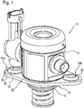
- a piston pump carries in FIG. 1 Overall, the reference numeral 10. It is used as a high-pressure fuel pump in an internal combustion engine of a motor vehicle, the latter are not shown in the figure.
- the piston pump 10 has a pump housing 12, which in an in FIG. 1 lower portion 14 has a circular outer contour. In this lower region 14, a centering portion 16 is formed, which in a receiving opening 18 (see FIG. 2 ) of a holding body, which in the present case is designed as a cylinder head 20 shown only schematically, can be introduced.
- a mounting flange 22 is welded to this.
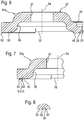
- This has a central portion 24 (see FIGS. 3 and 4 ), in which a circular opening 26 is present, the edge region of which is formed as a welding section 28, which is shown in FIG. FIG. 2 ) is welded to the pump housing 12.
- the weld 30 is welded through. The production of such a weld 30 is facilitated by an immediately above the weld 30 on the pump housing 12 existing circumferential recess 32, which can be prepared for example by a puncture.
- the mounting flange 22 is made as a sheet metal part made of stainless steel by stamping and cold forming. He has almost everywhere on a substantially equal thickness or sheet thickness. Only in the welding section 28, the thickness of the mounting flange 22 is significantly reduced.
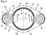
- wing portions 34a and 34b are formed, which are identical to each other. Below, therefore, for the sake of simplicity, only in the FIGS. 2 to 4 left wing portion 34a will be described in detail.
- the wing portion 34 a has a circular contour in plan view bulge 36 is impressed. In this concentric with the outer contour, a through hole 37 is present. At the top of the bulge 36 is supported via an integrally formed collar 38 (or optionally with the interposition of a washer) from a screw head 40 of a commercially available screw 42 (for example, an M6 screw of strength class 8.8) from. A threaded portion 44 of the screw 42 is passed through the through hole 37 and bolted in the cylinder head 20. Since the screw 42, which forms a connecting element to the cylinder head 20, supported on the bulge 36 and acts on this, the bulge 36 is also referred to as a connection region. By the configuration of the connection region as a bulge 36 has this in the in FIG. 2 shown installation position relative to the cylinder head 20 a distance D.
- contact area 46 The lying outside of the bulge 36 areas of the mounting flange 22 may, with the exception of the welding section 28, be referred to as contact area 46, since these rest in the installed position at least partially on the cylinder head 20, so contact this.
- the contact region 46 has a total of two dotted filled contact surfaces 48 and 50 and a base surface 52 which are provided on the side facing in the installed position to the cylinder head 20 of the contact portion 46 of the mounting flange 20.
- the first contact surface 48 extends concentrically around the opening 26 in the central portion 24 of the mounting flange 22, the pump housing 12 immediately adjacent. In that regard, in this embodiment, at least a portion of the first contact surface 48 between the connecting portion forming a recess 36 and the pump housing 12 is arranged.
- the second contact surface 50 is located at the outer edge of the wing portion 34a, so seen from the pump housing 12 from behind the bulge 36, and it has in plan view, the contour in about half a circular ring.
- the base surface 52 lies in the region of the attachment flange 22 which is outside the first two contact surfaces 48 and 50 and outside the bulge 36 and the welding section 28.
- FIG. 5 As can be seen, are the contact surfaces 48 and 50 and the base surface 52 seen in the direction of a longitudinal axis 54 before mounting the mounting flange 22 on the cylinder head 20, so before tightening the screw (s) 42, in different planes.
- a reference plane 56 is defined by the base surface 52.
- a plane 58, in which the first contact surface 48 is located, has a larger section D 48 from the reference plane 56 to the cylinder head 20 than a plane 60 in which the contact surface 50 lies and which only has a distance D 50 from the reference plane 56 ,
- the surface pressure is particularly high in the region of the first contact surface 48 immediately adjacent to the bulge 36, since this first comes into contact with the cylinder head 20 during screwing.
- the welding portion 28 is compared to the immediately adjacent to him first contact surface 48 seen from the cylinder head 20 from something set back. As a result, damage to the first contact surface 48 is prevented during the production of the weld seam 30.
- FIG. 6 an alternative embodiment of a mounting flange 22 is shown.
- those elements and regions which have equivalent functions to previously described elements and regions carry the same reference numerals. They are not explained again in detail.
- fastening flange 22 has at the radially projecting edge of the wing portions (in FIG. 6 is again only the wing portion 34 a shown) in the region of the second contact surface 50 a sharp and in the installed position in the direction of the cylinder head 20 projecting edge, which forms a Verkrallkante 62.
- the frictional engagement between the mounting flange 22 and the cylinder head 20 is increased again and a displacement transverse to the longitudinal axis 54 again better prevented.
- corresponding Verkrallkanten 62 can be made in the second contact surface 50 by conical impressions 64.
- conical impressions 64 By a corresponding arrangement of these conical impressions 64, a waffle-iron-like configuration of the second contact surface 50 can be produced.
- the contact surface 48 may be interrupted in the region of the bulge 36 by a portion 66 which is set back relative to the first plane 58, for example in the reference plane 56 or in the second plane 60 is located.
- the portion 66 extends in the present embodiment over an angular range of 20 ° on both sides of a central axis 68 of the wing portions 34a and 34b (the central axis 68 extends through the centers of the two bulges 36 and the screw (s) 42). It is also conceivable, however, an extent of 10 ° on both sides of this central axis 68 up to 45 ° on both sides of the central axis 68th
Landscapes
- Engineering & Computer Science (AREA)
- Mechanical Engineering (AREA)
- General Engineering & Computer Science (AREA)
- Chemical & Material Sciences (AREA)
- Combustion & Propulsion (AREA)
- Fuel-Injection Apparatus (AREA)
Claims (11)
- Pompe à piston (10), en particulier pompe à carburant haute pression pour un moteur à combustion interne d'un véhicule automobile, avec un carter de pompe (12) et une bride de fixation (22) qui est fixée et soudée sur le carter de pompe (12) et qui présente au moins une zone de raccordement (36) sur laquelle, dans la position montée, agit un élément de raccordement (42) par le biais duquel la pompe à piston (10) peut être fixée sur un corps de retenue (20), la zone de raccordement (36) étant, dans la position montée, à distance du corps de retenue (20), caractérisée en ce que la zone de raccordement est constituée en tant qu'indentation (36) dans ou sur une zone de contact (46) qui, dans la position montée, est au moins par tronçons adjacente au corps de retenue (20) .
- Pompe à piston (10) selon la revendication 1, caractérisée en ce que la zone de raccordement est estampée en tant qu'indentation (36) dans ou sur une zone de contact (46) qui, dans la position montée, est au moins par tronçons adjacente au corps de retenue (20) .
- Pompe à piston (10) selon l'une des revendications 1 et 2, caractérisée en ce qu'une zone de contact (46) présente au moins deux surfaces de contact (48, 50) dirigées vers le corps de retenue (20) qui, après le montage sur le corps de retenue (20), sont adjacentes au moins par tronçons à ce dernier et qui, au moins avant le montage, sont situées dans des plans (58, 60) qui ont des distances (D48, D50) différentes par rapport à un plan de référence (56) commun de telle sorte que, lors du montage, la bride de fixation (22) est serrée sur le corps de retenue (20) et/ou s'enfonce dans le corps de retenue (20).
- Pompe à piston (10) selon la revendication 3, caractérisée en ce que la zone de contact (46) comprend une première surface de contact (48) voisine du carter de pompe (12) et de préférence concentrique à celui-ci, une deuxième surface de contact (50) disposée derrière la zone de raccordement (36) vu à partir du carter de pompe (12), et une surface de base (52), la surface de base (52) étant située dans le plan de référence (56) et, avant le montage, le plan (58) de la première surface de contact (48) présentant, vu en direction du corps de retenue (20), une distance (D48) au plan de référence (56) plus grande que le plan (60) de la deuxième surface de contact (50).
- Pompe à piston selon la revendication 4, caractérisée en ce que, à proximité de la zone de raccordement (36), la première surface de contact (48) est interrompue par un tronçon (66) qui est situé dans un plan (56) en retrait par rapport au plan (58) de la première surface de contact (48), et en ce que le tronçon (66) s'étend de préférence sur une plage angulaire d'environ 20° à environ 90°.
- Pompe à piston (10) selon l'une des revendications précédentes, caractérisée en ce que, sur au moins une surface de contact (50), il y a au moins une arête d'accrochage (62), en particulier une pluralité d'arêtes d'accrochage (62) qui se croisent ou qui ont une forme de gaufrier.
- Pompe à piston (10) selon la revendication 6, caractérisée en ce qu'au moins une arête d'accrochage (62) est formée sur un bord de la bride de fixation (22) par une arête, en particulier une arête estampée, qui, dans la position montée, fait saillie vers le corps de retenue (20).
- Pompe à piston (10) selon l'une des revendications précédentes, caractérisée en ce que, en direction du carter de pompe (12), la bride de fixation (22) présente un tronçon soudé (28), réalisé en particulier par estampage, qui présente une épaisseur plus faible que la bride de fixation (22) restante, et en ce qu'un cordon de soudure (30) est soudé entre le tronçon soudé (28) et le carter de pompe (12).
- Pompe à piston (10) selon la revendication 8, caractérisée en ce que le tronçon soudé (28) est en retrait par rapport à une surface de contact (48) voisine et dirigée vers le corps de retenue (20).
- Pompe à piston (10) selon l'une des revendications précédentes, caractérisée en ce que la bride de fixation (22) est réalisée en tôle métallique, de préférence en tôle d'acier fin, par découpage et formage à froid, en particulier estampage.
- Pompe à piston (10) selon l'une des revendications précédentes, caractérisée en ce que la bride de fixation (22) est disposée à l'extérieur autour du carter de pompe (12) et présente au moins deux tronçons d'ailette (34a, 34b) qui dépassent, dans lesquels il y a respectivement une zone de raccordement (36).
Applications Claiming Priority (3)
| Application Number | Priority Date | Filing Date | Title |
|---|---|---|---|
| DE102004063073 | 2004-12-28 | ||
| DE102005007806A DE102005007806A1 (de) | 2004-12-28 | 2005-02-21 | Kolbenpumpe, insbesondere Hochdruck-Kraftstoffpumpe für eine Brennkraftmaschine eines Kraftfahrzeugs |
| PCT/EP2005/056734 WO2006069913A1 (fr) | 2004-12-28 | 2005-12-13 | Pompe a piston, en particulier pompe a carburant haute pression pour un moteur a combustion interne d'un vehicule automobile |
Publications (2)
| Publication Number | Publication Date |
|---|---|
| EP1834090A1 EP1834090A1 (fr) | 2007-09-19 |
| EP1834090B1 true EP1834090B1 (fr) | 2018-09-12 |
Family
ID=35929717
Family Applications (1)
| Application Number | Title | Priority Date | Filing Date |
|---|---|---|---|
| EP05821583.1A Expired - Lifetime EP1834090B1 (fr) | 2004-12-28 | 2005-12-13 | Pompe a piston, en particulier pompe a carburant haute pression pour un moteur a combustion interne d'un vehicule automobile |
Country Status (4)
| Country | Link |
|---|---|
| EP (1) | EP1834090B1 (fr) |
| DE (1) | DE102005007806A1 (fr) |
| ES (1) | ES2701345T3 (fr) |
| WO (1) | WO2006069913A1 (fr) |
Cited By (1)
| Publication number | Priority date | Publication date | Assignee | Title |
|---|---|---|---|---|
| KR20230036743A (ko) * | 2021-09-08 | 2023-03-15 | 주식회사 현대케피코 | 다중 면 접촉식 고압펌프 마운팅 장치 |
Families Citing this family (15)
| Publication number | Priority date | Publication date | Assignee | Title |
|---|---|---|---|---|
| DE102016206456B4 (de) * | 2016-04-18 | 2017-11-09 | Continental Automotive Gmbh | Kombination, umfassend ein Gehäuse und einen Flansch, und Anordnung |
| DE102016206459B3 (de) * | 2016-04-18 | 2017-10-05 | Continental Automotive Gmbh | Kombination, umfassend ein Gehäuse und einen Flansch, und Anordnung |
| DE102016206470B3 (de) * | 2016-04-18 | 2017-10-05 | Continental Automotive Gmbh | Kombination, umfassend ein Gehäuse und einen Flansch, und Anordnung |
| DE102016213451A1 (de) | 2016-05-19 | 2017-11-23 | Robert Bosch Gmbh | Kraftstoff-Hochdruckpumpe |
| DE102016212468A1 (de) | 2016-07-08 | 2018-01-11 | Robert Bosch Gmbh | Hochdruck-Kraftstoffpumpe für ein Kraftstoff-Einspritzsystem einer Brennkraftmaschine |
| DE102016213333A1 (de) | 2016-07-21 | 2018-01-25 | Robert Bosch Gmbh | Kraftstoff-Hochdruckpumpe |
| DE102017207207A1 (de) | 2017-04-28 | 2018-10-31 | Robert Bosch Gmbh | Kraftstoffpumpe |
| DE102017210313A1 (de) | 2017-06-20 | 2018-12-20 | Robert Bosch Gmbh | Kraftstoff-Hochdruckpumpe |
| DE102018209264A1 (de) | 2018-06-11 | 2019-12-12 | Robert Bosch Gmbh | Kraftstoff-Hochdruckpumpe |
| DE102018211690A1 (de) | 2018-07-13 | 2020-01-16 | Robert Bosch Gmbh | Kraftstoff-Hochdruckpumpe |
| DE102018216583A1 (de) * | 2018-09-27 | 2020-04-02 | Continental Automotive Gmbh | Verfahren zum Herstellen einer Pumpenanordnung für eine Brennkraftmaschine und Pumpenanordnung |
| DE102018216582A1 (de) * | 2018-09-27 | 2020-04-02 | Continental Automotive Gmbh | Pumpenanordnung für eine Brennkraftmaschine |
| DE102018221702A1 (de) | 2018-12-13 | 2020-06-18 | Robert Bosch Gmbh | Kraftstoff-Hochdruckpumpe |
| DE102019204995B4 (de) * | 2019-04-08 | 2024-03-07 | Vitesco Technologies GmbH | Pumpe für ein Kraftfahrzeug und Verfahren zum Herstellen einer Pumpe |
| GB2631716A (en) * | 2023-07-10 | 2025-01-15 | Perkins Engines Co Ltd | Retainer plate for retaining a pump body within a pump housing |
Family Cites Families (4)
| Publication number | Priority date | Publication date | Assignee | Title |
|---|---|---|---|---|
| CS191051B1 (en) * | 1975-03-27 | 1979-06-29 | Jaromir Indra | Injection unit of the injection pump for the combustion engines |
| IT1226115B (it) * | 1988-12-13 | 1990-12-11 | O M A P Officine Meccaniche Al | Pompa di iniezione ad alta pressione principalmente per motori diesel |
| DE10134066A1 (de) * | 2001-07-13 | 2003-02-06 | Bosch Gmbh Robert | Kraftstoffpumpe, insbesondere Hochdruck-Kraftstoffpumpe für ein Kraftstoffsystem einer Brennkraftmaschine mit Benzin-Direkteinspritzung |
| DE10322599B4 (de) * | 2003-05-20 | 2013-08-08 | Robert Bosch Gmbh | Kolbenpumpe, insbesondere Hochdruck-Kraftstoffpumpe |
-
2005
- 2005-02-21 DE DE102005007806A patent/DE102005007806A1/de not_active Withdrawn
- 2005-12-13 EP EP05821583.1A patent/EP1834090B1/fr not_active Expired - Lifetime
- 2005-12-13 WO PCT/EP2005/056734 patent/WO2006069913A1/fr not_active Ceased
- 2005-12-13 ES ES05821583T patent/ES2701345T3/es not_active Expired - Lifetime
Non-Patent Citations (1)
| Title |
|---|
| None * |
Cited By (2)
| Publication number | Priority date | Publication date | Assignee | Title |
|---|---|---|---|---|
| KR20230036743A (ko) * | 2021-09-08 | 2023-03-15 | 주식회사 현대케피코 | 다중 면 접촉식 고압펌프 마운팅 장치 |
| KR102604769B1 (ko) | 2021-09-08 | 2023-11-21 | 주식회사 현대케피코 | 다중 면 접촉식 고압펌프 마운팅 장치 |
Also Published As
| Publication number | Publication date |
|---|---|
| EP1834090A1 (fr) | 2007-09-19 |
| ES2701345T3 (es) | 2019-02-21 |
| WO2006069913A1 (fr) | 2006-07-06 |
| DE102005007806A1 (de) | 2006-07-06 |
Similar Documents
| Publication | Publication Date | Title |
|---|---|---|
| EP1834090B1 (fr) | Pompe a piston, en particulier pompe a carburant haute pression pour un moteur a combustion interne d'un vehicule automobile | |
| EP1307667B1 (fr) | Dispositif de montage elastique d'un groupe hydraulique d'un systeme de freinage dans un vehicule | |
| EP2971747B1 (fr) | Pompe haute pression, en particulier pompe enfichable, pour système d'injection de carburant d'un moteur à combustion interne | |
| DE2353548C3 (de) | Elastische Wellenkupplung | |
| DE2857679A1 (de) | Injection nozzle clamp | |
| DE69903116T2 (de) | Klemmvorrichtung für Einspritzventile | |
| EP2730456B1 (fr) | Entraînement d'un dispositif de réglage de siège pour véhicules automobiles | |
| EP1389701B1 (fr) | Joint plat à couches multiples et méthode pour joindre les couches d'un tel joint | |
| DE102010052781A1 (de) | Befestigungsvorrichtung und Befestigungsbaugruppe zur Befestigung eines Gasgenerators und Fahrzeuginsassenrückhaltesystem | |
| DE69205768T2 (de) | Haltemutter. | |
| DE4004199A1 (de) | Verbindungsvorrichtung fuer eine fahrzeug-antriebsquelle | |
| EP3569879A1 (fr) | Agencement flottant imperdable d'un élément de raccordement à un composant | |
| DE102010030033B4 (de) | Befestigungsanordnung zur Anbringung eines Fahrzeugheizgeräts an einer Trägerstruktur | |
| EP1772633B1 (fr) | Liaison par vissage de deux éléments avec compensation de tolérance | |
| DE202016106796U1 (de) | Fahrzeugsitz | |
| DE102012011609A1 (de) | Unterlegelement zur Befestigung eines Abgaskrümmers an einem Verbrennungsmotor, Abgaskrümmer und Verbrennungsmotor | |
| EP3203048B1 (fr) | Système de fixation d'un tuyau coudé de sortie sur une culasse de cylindre d'un moteur à combustion interne | |
| EP1903219B1 (fr) | Dispositif pour la fixation d'un composant sur un élément de support | |
| DE10219829B4 (de) | Vorrichtung zum Befestigen eines Abgaskrümmers | |
| DE102004036518B4 (de) | Verdrehsichere Dichtkegelverbindung bei Einspritzleitungen zur Kraftstoffeinspritzung und Verfahren zu deren Herstellung | |
| EP0930439B1 (fr) | Fixation d'au moins deux tôles l'une sur l'autre au moyen d'une vis auto-foreuse | |
| EP3415456B1 (fr) | Pare-chocs de sécurité pour un élévateur ou pour une grue | |
| WO2008138702A1 (fr) | Culbuteur d'un moteur à combustion interne | |
| DE102012019039A1 (de) | Flanschverbindung und Kraftfahrzeug mit einer solchen Flanschverbindung | |
| EP4428084B1 (fr) | Dispositif d'isolation acoustique pour ascenseurs et agencement d'ascenseur |
Legal Events
| Date | Code | Title | Description |
|---|---|---|---|
| PUAI | Public reference made under article 153(3) epc to a published international application that has entered the european phase |
Free format text: ORIGINAL CODE: 0009012 |
|
| 17P | Request for examination filed |
Effective date: 20070730 |
|
| AK | Designated contracting states |
Kind code of ref document: A1 Designated state(s): AT BE BG CH CY CZ DE DK EE ES FI FR GB GR HU IE IS IT LI LT LU LV MC NL PL PT RO SE SI SK TR |
|
| DAX | Request for extension of the european patent (deleted) | ||
| RBV | Designated contracting states (corrected) |
Designated state(s): AT BE BG CH CY CZ DE DK EE ES FI FR GB GR HU IE IS IT LI LT LU LV MC NL PL PT RO SE SI SK TR |
|
| RBV | Designated contracting states (corrected) |
Designated state(s): DE ES FR IT |
|
| 17Q | First examination report despatched |
Effective date: 20150203 |
|
| GRAP | Despatch of communication of intention to grant a patent |
Free format text: ORIGINAL CODE: EPIDOSNIGR1 |
|
| INTG | Intention to grant announced |
Effective date: 20180329 |
|
| RIC1 | Information provided on ipc code assigned before grant |
Ipc: F04B 1/04 20060101AFI20180319BHEP Ipc: F02M 59/48 20060101ALI20180319BHEP Ipc: F02M 59/02 20060101ALI20180319BHEP |
|
| GRAS | Grant fee paid |
Free format text: ORIGINAL CODE: EPIDOSNIGR3 |
|
| GRAA | (expected) grant |
Free format text: ORIGINAL CODE: 0009210 |
|
| AK | Designated contracting states |
Kind code of ref document: B1 Designated state(s): DE ES FR IT |
|
| REG | Reference to a national code |
Ref country code: DE Ref legal event code: R096 Ref document number: 502005015906 Country of ref document: DE |
|
| REG | Reference to a national code |
Ref country code: ES Ref legal event code: FG2A Ref document number: 2701345 Country of ref document: ES Kind code of ref document: T3 Effective date: 20190221 |
|
| REG | Reference to a national code |
Ref country code: DE Ref legal event code: R097 Ref document number: 502005015906 Country of ref document: DE |
|
| PLBE | No opposition filed within time limit |
Free format text: ORIGINAL CODE: 0009261 |
|
| STAA | Information on the status of an ep patent application or granted ep patent |
Free format text: STATUS: NO OPPOSITION FILED WITHIN TIME LIMIT |
|
| 26N | No opposition filed |
Effective date: 20190613 |
|
| PGFP | Annual fee paid to national office [announced via postgrant information from national office to epo] |
Ref country code: FR Payment date: 20221220 Year of fee payment: 18 |
|
| PGFP | Annual fee paid to national office [announced via postgrant information from national office to epo] |
Ref country code: ES Payment date: 20230119 Year of fee payment: 18 |
|
| REG | Reference to a national code |
Ref country code: DE Ref legal event code: R084 Ref document number: 502005015906 Country of ref document: DE |
|
| PGFP | Annual fee paid to national office [announced via postgrant information from national office to epo] |
Ref country code: IT Payment date: 20221230 Year of fee payment: 18 |
|
| PG25 | Lapsed in a contracting state [announced via postgrant information from national office to epo] |
Ref country code: FR Free format text: LAPSE BECAUSE OF NON-PAYMENT OF DUE FEES Effective date: 20231231 |
|
| PG25 | Lapsed in a contracting state [announced via postgrant information from national office to epo] |
Ref country code: FR Free format text: LAPSE BECAUSE OF NON-PAYMENT OF DUE FEES Effective date: 20231231 |
|
| REG | Reference to a national code |
Ref country code: ES Ref legal event code: FD2A Effective date: 20250128 |
|
| PGFP | Annual fee paid to national office [announced via postgrant information from national office to epo] |
Ref country code: DE Payment date: 20250224 Year of fee payment: 20 |
|
| PG25 | Lapsed in a contracting state [announced via postgrant information from national office to epo] |
Ref country code: ES Free format text: LAPSE BECAUSE OF NON-PAYMENT OF DUE FEES Effective date: 20231214 |
|
| PG25 | Lapsed in a contracting state [announced via postgrant information from national office to epo] |
Ref country code: IT Free format text: LAPSE BECAUSE OF NON-PAYMENT OF DUE FEES Effective date: 20231213 |
|
| REG | Reference to a national code |
Ref country code: DE Ref legal event code: R071 Ref document number: 502005015906 Country of ref document: DE |