EP1834432B1 - Procédé et structure de transmetteur pour la réduction d'ambiguité à réarrangement de répétition dans le domain symbole - Google Patents
Procédé et structure de transmetteur pour la réduction d'ambiguité à réarrangement de répétition dans le domain symbole Download PDFInfo
- Publication number
- EP1834432B1 EP1834432B1 EP05761790A EP05761790A EP1834432B1 EP 1834432 B1 EP1834432 B1 EP 1834432B1 EP 05761790 A EP05761790 A EP 05761790A EP 05761790 A EP05761790 A EP 05761790A EP 1834432 B1 EP1834432 B1 EP 1834432B1
- Authority
- EP
- European Patent Office
- Prior art keywords
- mapping
- data word
- sub
- values
- modulation states
- Prior art date
- Legal status (The legal status is an assumption and is not a legal conclusion. Google has not performed a legal analysis and makes no representation as to the accuracy of the status listed.)
- Expired - Lifetime
Links
Images







Classifications
-
- H—ELECTRICITY
- H04—ELECTRIC COMMUNICATION TECHNIQUE
- H04L—TRANSMISSION OF DIGITAL INFORMATION, e.g. TELEGRAPHIC COMMUNICATION
- H04L27/00—Modulated-carrier systems
- H04L27/02—Amplitude-modulated carrier systems, e.g. using on-off keying; Single sideband or vestigial sideband modulation
-
- H—ELECTRICITY
- H04—ELECTRIC COMMUNICATION TECHNIQUE
- H04L—TRANSMISSION OF DIGITAL INFORMATION, e.g. TELEGRAPHIC COMMUNICATION
- H04L27/00—Modulated-carrier systems
- H04L27/18—Phase-modulated carrier systems, i.e. using phase-shift keying
-
- H—ELECTRICITY
- H04—ELECTRIC COMMUNICATION TECHNIQUE
- H04L—TRANSMISSION OF DIGITAL INFORMATION, e.g. TELEGRAPHIC COMMUNICATION
- H04L1/00—Arrangements for detecting or preventing errors in the information received
- H04L1/12—Arrangements for detecting or preventing errors in the information received by using return channel
- H04L1/16—Arrangements for detecting or preventing errors in the information received by using return channel in which the return channel carries supervisory signals, e.g. repetition request signals
- H04L1/18—Automatic repetition systems, e.g. Van Duuren systems
- H04L1/1867—Arrangements specially adapted for the transmitter end
- H04L1/1893—Physical mapping arrangements
-
- H—ELECTRICITY
- H04—ELECTRIC COMMUNICATION TECHNIQUE
- H04L—TRANSMISSION OF DIGITAL INFORMATION, e.g. TELEGRAPHIC COMMUNICATION
- H04L27/00—Modulated-carrier systems
- H04L27/32—Carrier systems characterised by combinations of two or more of the types covered by groups H04L27/02, H04L27/10, H04L27/18 or H04L27/26
- H04L27/34—Amplitude- and phase-modulated carrier systems, e.g. quadrature-amplitude modulated carrier systems
-
- H—ELECTRICITY
- H04—ELECTRIC COMMUNICATION TECHNIQUE
- H04L—TRANSMISSION OF DIGITAL INFORMATION, e.g. TELEGRAPHIC COMMUNICATION
- H04L1/00—Arrangements for detecting or preventing errors in the information received
- H04L1/0001—Systems modifying transmission characteristics according to link quality, e.g. power backoff
- H04L1/0002—Systems modifying transmission characteristics according to link quality, e.g. power backoff by adapting the transmission rate
- H04L1/0003—Systems modifying transmission characteristics according to link quality, e.g. power backoff by adapting the transmission rate by switching between different modulation schemes
Definitions
- the invention relates to digital communication systems. It is particularly applicable to communication systems where data is transmitted over a time-variant or frequency-variant channel, such as in mobile communication systems or satellite communication.
- modulated signals For transmission over long distances or wireless links, digital data is modulated onto one or more carriers.
- modulation schemes are known in prior art, such as amplitude shift keying (ASK), phase shift keying (PSK) and mixed amplitude and phase modulation like quadrature amplitude modulation, QAM.
- ASK amplitude shift keying
- PSK phase shift keying
- QAM quadrature amplitude modulation
- mapping The assignment between bit sequence and complex values is called mapping.
- a data word consisting of a b-bit bit sequence results in a mapping of 2 b bit sequences to 2 b complex values.
- EP 1 293 059 B1 shows a method to rearrange digital modulation symbols in order to improve the mean reliabilities of all bits. This is achievable by changing the mapping rule of bits onto modulation symbols. This patent focuses on the rearrangement for retransmitted data words in an ARQ system.
- WO 2004 036 817 and WO 2004 036 818 describe how to achieve the reliability averaging effect for a system where an original and a repeated data word are transmitted over different diversity branches, or in combination with an ARQ system.
- a major difference between wired communication systems and wireless communication systems is the behaviour of the physical channel over which information is transmitted.
- the wireless or mobile channel is by its very nature variant over time and/or frequency.
- a demodulation of data symbols in a receiver requires an accurate estimation of the channel, usually measured by a channel coefficient, which includes knowledge about the power, the phase, or both properties of the channel.
- a channel coefficient which includes knowledge about the power, the phase, or both properties of the channel.
- pilot symbols are inserted into or between the data symbol stream which have a predetermined unambiguous amplitude and/or phase value, which can be used to determine the channel coefficient. This information is then used for correction measures like adaptive filtering.
- Decision-Feedback Demodulation is an iterative process where a first rough channel estimate (or none at all) is used to demodulate the data symbols. After demodulation, and preferably after decoding, the obtained information is fed back to the channel estimator for an improved estimation resulting from the data symbols. It should be apparent that this process causes not only delay and requires a lot of computations in each iteration step, but it also depends greatly on the quality of the first rough channel estimate due to the feedback loop. Such procedure is known for example from Lutz H.-J.
- DE 101 56 822 A1 relates to a method that comprises distributing different modulation symbols in the quadrants of a complex signal space in four quadrant groups and marking them with different amplitude and phase values.
- Each data bit sequence for transmission is mapped to a modulation symbol that is part of one of the groups in the quadrants.
- the signal amplitude of each quadrant group can be controlled so that the distance between the quadrant groups can be increased or decreased relative to the distance between the modulation symbols within a respective quadrant group.
- the invention defines a special way of mapping repeated data words onto signal constellation points.
- a rearranged constellation pattern is selected that reduces the number of ambiguities when the original and the repeated data symbols are combined. That is, the number of different results that can be obtained by adding the complex values or vectors in the complex number plane representing the constellation points of a first transmission and of a re-transmission of the same data word is lower than the number of original constellation points or modulation states. This reduced number of ambiguities facilitates a better channel estimation, less dependent on or independent of the actual data symbol transmitted.
- Step b is optional in both cases, as it is not required for the reduction of ambiguity. However it provides the advantage of uniform transmission power on the channel over transmitted and re-transmitted signals.
- the counterpart constellation(s) can be generated by the following method:
- the mentioned mirroring is mathematically exact.
- An approximate mirroring would be sufficient in a real system. Approximate means that the distance between the actual constellation point and the ideal mirrored position is less than half the distance to the closest constellation point representing a different value of the data word. Such approximate mirroring may be beneficially employed in a fixed-point representation of the complex values, where the mathematically exact solution cannot be represented due the reduced accuracy of fixed-point numbers.
- constellations that are symmetrical to at least one arbitrary axis in the complex plane preferably a division into two half-planes is done with respect to such a symmetry axis that does not include any signal point.
- that respective axis is used; otherwise the symmetry axis will be tilted.
- this method may result in counterpart constellations that are different in shape than the original constellation if the constellation is not point-symmetric to the mirroring point within each sub-plane. This is particularly true if the original constellation represents a PSK or any mixed ASK/PSK modulation apart from QAM.
- step 1 to step 3 of the counterpart constellation generation should then be altered as follows:
- mapping of a word using the original constellation i.e. the mapping of a data word onto a complex value according to the original constellation
- mapping of a data word using a counterpart constellation i.e. the mapping of a data word onto a complex value according to a counterpart constellation, results in the counterpart constellation symbol or simply counterpart symbol.
- a method for transmitting data in a digital communication system comprises a first transmission step (1205) transmitting a data word modulated on a carrier according to a first mapping (401) of data word values to modulation states; and at least one further transmission step (1206) transmitting the same data word modulated on a carrier according to at least one further mapping (402) of data word values to modulation states, wherein a number of different combined values obtainable (410, 411), (712, 713), (811- 814) for all data word values, by adding for each data word value complex values associated with said data word value according to said first and at least one of said further mappings, is lower than the number of different data word values within said first mapping (401, 701, 801).
- a method for transmitting data in a digital communication system comprises the steps of transmitting a data word modulated on a carrier according to a first mapping of data word values to modulation states; and transmitting the data word modulated on a carrier according to a second mapping of data word values to modulation states, wherein the second mapping of data word values to modulation states is obtained from the first mapping of data word values to modulation states by: i. dividing a complex plane representing the first mapping of data word values to modulation states into at least two sub-planes (404, 405); ii.
- a method for transmitting data in a digital communication system comprises m transmission steps of transmitting a data word modulated on a carrier according to the first mapping of data word values to modulation states; and transmitting the data word m-1 times, modulated on a carrier according to m-1 further mappings of data word values to modulation states, wherein the m-1 further mappings of data word values to modulation states are obtained from the first mapping by i. dividing a complex plane representing the first mapping of data word values to modulation states into sub-planes (706, 707), the number of modulation states within at least a part of the sub-planes being m; and ii. assigning to at least a part of the data word values different modulation states within the same sub-plane, one for each mapping.
- a method for transmitting data in a digital communication system employing phase-shift key modulation comprises the steps of transmitting a data word modulated on a carrier according to a first mapping of data word values to modulation states; and transmitting the data word modulated on a carrier according to a second mapping of data word values to modulation states, wherein the second mapping of data word values to modulation states is obtained from the first mapping of data word values to modulation states by i.
- a computer-readable storage medium has stored thereon program instructions that, when executed in a processor of a transmitter of a digital communication system, cause the transmitter to perform a method according to one of the aspects described above.
- a transmitter (1300) for a digital communication system comprises a repeater (1304) for receiving data words and for repeating the received data words at least once; and a mapper (1310) for mapping the data words and their repetitions to modulation states according to their values.
- the mapper is configured for a) mapping a data word to a modulation state according to a first mapping of data word values to modulation states; and b) mapping the at least one repetition of the data word to a modulation state according to at least one further mapping of data word values to modulation states.
- the transmitter further comprises a mapping control unit (1306) configured for providing to said mapper said first and said at least one further mapping, wherein a number of different combined states obtainable, for all data word values, by adding for each data word value complex values of modulation states associated with said data word value according to said first and at least one of said further mappings, is lower than a number of different data word values within said first mapping of data word values to modulation states.
- the transmitter further comprises a modulator (1311) for modulating a carrier according to the modulation states.
- a transmitter (1300) for a digital communication system comprises a repeater (1304) for receiving data words and for repeating the received data words once; and a mapper (1305) for mapping the data words and their repetitions to modulation states according to their values.
- the mapper is configured for a) mapping a data word to a modulation state according to a first mapping of data word values to modulation states; and b) mapping the repetition of the data word to a modulation state according to a second mapping of data word values to modulation states.
- the transmitter further comprises a mapping control unit (1306) configured for providing to said mapper said first and said second mapping, wherein the second mapping of data word values to modulation states is obtained from said first mapping of data word values to modulation states by i. dividing a complex plane representing the first mapping of data word values to modulation states into sub-planes; ii. calculating an average value of complex values of all modulation-states contained in each of at least a part of the sub-planes; and iii.
- the transmitter further comprises a modulator (1311) for modulating a carrier according to the modulation states.
- a transmitter (1300) for a digital communication system comprises a repeater (1304) for receiving data words and for repeating the received data words m-1 times; a mapper (1305) for mapping the data words and their repetitions to modulation states according to their values and according to m different mappings of data word values to modulation states; and a mapping control unit (1306) configured for providing to said mapper said m mappings, wherein m-1 further mappings of data word values to modulation states are obtained from a first mapping of data word values to modulation states by i.
- the transmitter further comprises a modulator (1311) for modulating a carrier according to said modulation states.
- a transmitter (1300) for a digital communication system employing phase-shift key modulation comprises a repeater (1304) for receiving data words and for repeating the received data words once; and a mapper (1305) for mapping the data words and their repetitions to modulation states according to their values.
- the mapper is configured for a) mapping a data word to a modulation state according to a first mapping of data word values to modulation states; and b) mapping the repetition of the data word to a modulation state according to a second mapping of data word values to modulation states.
- the transmitter further comprises a mapping control unit (1306) configured for providing to said mapper said first and said second mapping, wherein the second mapping of data word values to modulation states is obtained from said first mapping of data word values to modulation states by i. dividing a complex plane representing the first mapping of data word values to modulation states into sub-planes, at least a part of the sub-planes having a symmetry axis with respect to positions of all complex values of modulation states comprised in the sub-plane; and ii.
- the transmitter further comprises a modulator (1311) for modulating a carrier according to the modulation states.
- a base station (1400) of a digital wireless communication system comprises the transmitter (1300) according to one of the aspects described above.
- a mobile station (1500) of a digital wireless communication system comprises the transmitter (1300) according to one of the aspects described above.
- mappings or constellations a point is identified by a numeric label. It should be apparent to those skilled in the art that this labelling is meant to represent a given data word or bit sequence in the context of communication; the labels themselves are solely used to represent a fixed but arbitrary data word; sequential labels therefore do not have to represent sequential bit sequences in terms of their binary, octal, decimal, hexadecimal, or other numeric representation.
- Figure 2 shows an example of a transmission using the 16-QAM modulation scheme.
- Table 1 such a data modulation symbol carries four bits. In the method described herein, these four bits are transmitted twice:
- the complex plane is divided along imaginary axis 203 into two sub-planes 204 and 205.
- the imaginary axis is a symmetry axis.
- Diagonal line 206 might also be used, but it is advantageous to select a parting line for both sub-planes, on which no constellation points are located.
- symmetry axes for both sub-planes are determined.
- the real axis 207 is a symmetry axis for both sub-planes.
- the position of a constellation point in the counterpart constellation has to be mirrored with respect to a point 208, 209 on the symmetry axis, that is the real axis 207, from the original constellation point.
- all constellation points belonging to sub-plane 204 have to be mirrored with respect to point 208, while all constellation points belonging to sub-plane 205 have to be mirrored with respect to point 209.
- this mirroring point 208, 209 should be equal to the average of all complex values in this sub-plane.
- Figure 3 shows a first 301 and a further mapping 302 for 64-QAM.
- the complex plane is divided into two sub-planes along the imaginary axis 303.
- each constellation point is mirrored from its original position in the first constellation with regard to the average complex value 304, 305 in the same sub-plane, respectively according to the sub-plane to that a constellation point belongs.
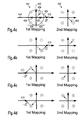
- the counterpart (second) mapping 502 results in a mixed ASK/PSK constellation.
- Figure 6 shows a similar situation for the case that the original (first) mapping is a 16-PSK scheme. If the ambiguity is to be reduced to a BPSK equivalence, then the counterpart (second) mapping is quite irregular.
- the complex plane of original constellation (first mapping) 701 is divided into two sub-planes 706 and 707 by imaginary axis 705.
- the mappings of a given data word onto a constellation point are permuted such that the same word is assigned exactly once to each position (constellation point) in its sub-plane within all mappings 701-704. Consequently, coherent combining of all four transmissions of the same word results in the same value, independent of the word value.
- word number "1" is represented by vector 708 in the first mapping 701, by vector 709 in second mapping 702, by vector 710 in the third mapping 703 and by vector 711 in mapping 704.
- the result 712 is the real value of roughly 2.6131 for all word values assigned to the right half plane, as for all word values the same vectors are added, just in different order.
- the real value of roughly -2.6131 is the result 713 for all values assigned to the left half-plane. Consequently a BPSK-equivalent situation of one amplitude and two phase levels can be achieved by using four mappings of words onto constellation points.
- the complex plane is divided along imaginary axis 803 into sub-planes 804 and 805.
- the position is mirrored with regard to the real axis 806, which is a symmetry axis for both sub-planes.
- the combination of first (original) transmission and repeated transmission of word number "1" is the sum of vectors 807 and 808, which yields the real value of roughly 0.7654 at point 812. The same would hold true for word number "4".
- the result is roughly 1.8478 at point 811.
- Figure 9 shows 8 different mappings for 16-PSK. If only first and second mapping are combined, 8 results are possible as shown in Fig. 10a (four amplitude levels and two phase levels). When the first four mappings are combined, four results occur, as shown in Fig. 10b (two amplitude levels and two phase levels). Only when all 8 mappings are combined, ambiguity is reduced to 2 phase levels.
- Data frame 1101 contains data transmitted according to prior art, in this case with constellation rearrangement.
- data frame 1102 contains only data transmitted according to the method presented herein.
- Data frame 1103 contains data transmitted according to both methods.
- Data word 1104, transmitted using a first (original) mapping, is repeated as data word 1105 according to a second mapping as described in detail above. The same applies to data word 1106, which is re-transmitted as data word 1107.
- the amount and position of ReRe data symbols may be additionally signalled in a Control Channel explicitly or by means of a predefined parameter from the transmitter to the receiver, to provide the receiver with knowledge which part of the data frame follows which repetition strategy.
- an original symbol and its counterpart symbol(s) are transmitted in adjacent places within a time frame, since the benefit of repetition rearrangement depends on channel conditions that are as equal as possible for original and counterpart symbols.
- the original and counterpart symbol can be transmitted on adjacent subcarriers, in adjacent time slots, or both. The latter possibility is particularly applicable when there are several counterpart symbols to be transmitted with the same original symbol, for example three counterpart symbols for 8-PSK.
- the first counterpart symbol can be transmitted in an adjacent time slot in the same subcarrier as the original symbol; the second counterpart symbol can be transmitted in the same time slot in an adjacent subcarrier to the original symbol; the third counterpart symbol can be transmitted in an adjacent subcarrier in an adjacent time slot to the original symbol.
- mapping constellations that result in combined signal points that come to lie on the right axis in the graphs, usually representing the real part axis in the complex signal plane. It should be apparent to those skilled in the art that other mappings can be defined that reach a reduced number of ambiguities without resulting in combined signal points on the real axis. For example, it is very easy to define QAM mappings that result in signal points on the imaginary axis. Likewise it is easily possible to define mappings for PSK that result in points on a straight line inclined at a certain angle to the real axis. Which of such mappings is chosen can be an implementational choice of the system designer, and has no direct influence on the technical concept as far as this invention is concerned.
- a control word is pre-pended to each data word.
- the control word assumes a specific value for each transmission, e.g. "1" for the first transmission of a data word, "2" for the second transmission of the same data word, and so on.
- the super-mapping maps the different values of concatenated control word and data word to modulation states or super-constellation points. Thus, different mappings from data word values to modulation states are obtained for different values of the control word. If the super-mapping is arranged in an appropriate way, the different mappings from data word values to modulation states may exhibit the properties described above.
- Figure 16a shows an original constellation for the example 8-PSK
- Figure 16b shows the related counterpart constellation.
- constellation point 1601 represents symbol "1" in a first transmission
- constellation point 1602 represent the same symbol in a second transmission or re-transmission.
- Figure 17a shows an original constellation for the example 16-QAM
- Figure 17b shows the related counterpart constellation. It may be noted that the difference to the constellations shown in Figure 2 is limited to different labels of the constellation points, following the same reason as described above for Figures 16a-c . From the constellations in Figures 17a and 17b the super-constellation in Figure 17c is obtained by including the constellation points from both constellations, prepending a leading "0" or "1" to the label to signify whether this constellation point was generated using the original or the counterpart mapping respectively. Since the positions of constellation points are identical, and the original and counterpart constellations vary only in the labelling, in Figure 16c each constellation point has to represent two labels.
- constellation point 1701 represents value “1” in a first transmission and value "4" in a second transmission or re-transmission. Consequently, it represents the values "01" and "14" in the super-constellation.
- point 1702 represents “4" in the first transmission and "1” in the second transmission. In the super constellation of figure 17c it represents the values "04" and "11".
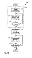
- Figure 12 shows a flow chart for a method which may be used to reduce the ambiguities in data symbols in a digital communication system. The method consists of a mapping generation step 1201, a transmission step 1205 and one or more re-transmission steps 1206.
- a first mapping is generated in step 1202.
- This mapping may be generated at random, according to a specified algorithm or by simply reading it from a table stored in the transmitter employing this method.
- This table may further be received from another entity like a base station or a mobile station for which the transmission is designated.
- a further step 1203 then generates a second mapping according to one of the algorithms given above.
- Step 1204 queries whether more mappings should be generated. In this case the loop returns to step 1203. If not, the method proceeds with step 1205.
- the generated mappings may be stored in the table for later use. Therefore the generation step 1201 is not necessarily required for each transmission session or even for each transmitted data word.
- step 1205 a symbol is transmitted according to the first mapping representing a data word.
- the same data word is transmitted again as a re-transmit symbol in step 1206 according to a second mapping generated in step 1203.
- Step 1207 queries whether more mappings exist according to which the data word should be transmitted. If this is the case, the method goes back to repeat steps 1206 and 1207. If no further mapping exists, the method ends the transmission of this data word. Although all transmissions of the same data word should advantageously be sent in close temporal proximity, other data words might be transmitted in between.
- a transmitter 1300 is illustrated which can be used to transmit data according to the method described above.
- an information bit stream to be transmitted is encoded in encoder 1301.
- the encoded bit stream is interleaved in random bit interleaver 1302.
- S/P unit 1303 groups of bits are combined to data words.
- data words are repeated for re-transmission. The repetition factor and the ratio of data words to be repeated is depending on the particular version of the method.
- the generated words are sent to mapper 1305.
- Mapper 1305 may work according to different modes.
- mapping control unit 1306 which selects the mapping mode to be applied to the words. If the third mode is selected, mapper 1305 receives mapping information from mapping control unit 1306 which may comprise a memory 1307 for storing a table containing mapping information.
- Mapping control unit 1306 is further configured to select in the third mapping mode the second and further mappings (i.e. counterpart mappings or counterpart constellations) for the re-transmissions derived from the first mapping used for the first transmission according to the rules defined above.
- the mappings may be calculated at run time according to the rules given above. Alternatively they may be read out from the table in memory 1307 where they have previously been stored according to a communication system design.
- mapping modes as described above may be used alternatively, according to information provided by the network or by the receiving unit. Further they may be used alternately within a single frame according to a pre-defined pattern like with frame 1103 shown in Fig. 11 . Information about such a pattern, as well as information about the mappings used may be sent to the receiving unit via control data transmitter 1308 and transmission channel 1312. Further, repetition control unit 1309 controls the repetition factor of repeater 1304 according to the requirements of mapping control unit 1306. For example, in the third mapping mode repetition control unit 1309 receives information from mapping control unit 1306 about the number of repetitions required for the selected mapping.
- pilot data is added and frames are combined in Pilot/Data frame creation unit 1310 before the information is modulated onto a carrier in modulator 1311.
- the modulated signal is sent to a receiving entity via channel 1312.
- transmitter 1300 may comprise further units like IF stage, mixers, power amplifier or antenna. From a signal flow point of view, such units might also be seen comprised in channel 1312, as they all may add noise to the signal or exert phase shift or attenuation on the signal.
- Units 1301 to 1311 may be implemented in dedicated hardware or in a digital signal processor.
- the processor performs the method described herein by executing instructions read from a computer-readable storage medium like read-only memory, electrically erasable read-only memory or flash memory. These instructions may further be stored on other computer-readable media like magnetic disc, optical disc or magnetic tape to be downloaded into a device before it is brought to use. Also mixed hardware and software embodiments are possible.
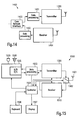
- Transmitter 1300 may be part of a base station 1400 as shown in figure 14 .
- a base station may further comprise a suitable receiver 1404, data processing units 1401 and 1402 and a core network interface 1403.
- a counterpart to base station 1400 might be a mobile station 1500 as shown in Fig. 15 .
- a mobile station may further comprise antenna 1501, antenna switch 1502, data processing unit 1503 and controller 1504.
- Mobile station 1500 might be a mobile phone or a module to be integrated into a portable computer, PDA, vehicle, vending machine or the like.
- a mobile phone may further comprise mixed signal unit 1505 and a user interface comprising keyboard 1506, display 1507, speaker 1508 and microphone 1509.
- a method and a receiver according to the present invention may advantageously improve the reliability of the channel estimation in a digital communication system.
- a better channel estimation has the advantage of reduced error rates and may provide connection with wireless communication systems in areas of weak coverage, fast fading conditions and other adverse circumstances.
Landscapes
- Engineering & Computer Science (AREA)
- Computer Networks & Wireless Communication (AREA)
- Signal Processing (AREA)
- Digital Transmission Methods That Use Modulated Carrier Waves (AREA)
- Detection And Prevention Of Errors In Transmission (AREA)
- Medicines Containing Antibodies Or Antigens For Use As Internal Diagnostic Agents (AREA)
- Mobile Radio Communication Systems (AREA)
Claims (26)
- Procédé permettant de transmettre des données dans un système de communication numérique, le procédé comprenant :a) une première étape de transmission (1205) transmettant un mot de données modulé sur une porteuse en fonction d'un premier mappage (401) de valeurs de mots de données sur des états de modulation, etb) au moins une étape de transmission supplémentaire (1206) transmettant le même mot de données modulé sur une porteuse en fonction d'au moins un mappage supplémentaire différent (402) desdites valeurs de mots de données sur des états de modulation,
dans lequel l'état de modulation, qui est obtenu à partir d'une somme des vecteurs, ladite somme des vecteurs étant produite en additionnant des valeurs complexes représentant respectivement lesdites valeurs de mots de données en fonction dudit premier et d'au moins l'un desdits mappages supplémentaires desdits mots de données, appartient à un ensemble d'états de modulation présentant un certain nombre qui est inférieur au nombre de différents états de modulation dudit premier mappage (401, 701, 801). - Procédé selon la revendication 1, dans lequel la valeur complexe d'une valeur de mot de données est sa phase et l'amplitude de son état de modulation.
- Procédé selon la revendication 1, dans lequel le nombre de niveaux d'ambiguïtés est réduit dans ledit ou lesdits mappages supplémentaires par comparaison au nombre dans ledit premier mappage.
- Procédé selon l'une des revendications 1 à 3, dans lequel le second mappage de valeurs de mots de données sur des états de modulation est obtenu à partir du premier mappage de valeurs de mots de données sur des états de modulation :i. en divisant le plan complexe représentant le premier mappage de valeurs de mots de données sur des états de modulation en au moins deux sous plans (404, 405),ii. en déterminant des axes de symétrie (412) pour au moins une partie des sous plans par rapport aux états de modulation compris dans chacune des parties des sous plans, etiii. en affectant à au moins une partie des valeurs de mots de données une valeur complexe (409), dans ledit second mappage (402), présentant une position dans le plan complexe qui est approximativement la position miroir de la position (408) d'une valeur complexe affectée au dit mot de données en fonction dudit premier mappage (400), par rapport à un point (407) situé sur l'axe de symétrie d'un sous plan (405) dans lequel est située la valeur complexe (408) conforme au dit premier mappage (401).
- Procédé selon la revendication 4, dans lequel, à l'étape iii, le point (407) sur l'axe de symétrie (412), servant de centre de duplication, représente une moyenne de la totalité des valeurs complexes affectées à au moins ladite partie des états de modulation dans le premier mappage (401) et situées dans ledit sous plan (405).
- Procédé selon l'une des revendications 1 à 3, dans lequel il y a m - 1 étapes supplémentaires de transmission dans l'étape b), et dans lequel les m - 1 mappages supplémentaires résultants de valeurs de mots de données sur des états de modulation sont obtenus à partir du premier mappage :i. en divisant le plan complexe représentant le premier mappage de valeurs de mots de données sur des états de modulation en des sous plans (706, 707), le nombre d'états de modulation dans au moins une partie des sous plans étant m, etii. en affectant à au moins une partie des valeurs de mots de données des états de modulation différents à l'intérieur du même sous plan, un seul pour chaque mappage.
- Procédé selon l'une des revendications 1 à 3, dans lequel le second mappage de valeurs de mots de données sur des états de modulation est obtenu à partir du premier mappage de valeurs de mots de données sur des états de modulation :i.en divisant le plan complexe représentant le premier mappage de valeurs de mots de données sur des états de modulation en des sous plans (804, 805), au moins une partie des sous plans présentant un axe de symétrie (806) par rapport aux positions de la totalité des états de modulation compris dans le sous plan,ii. en déterminant des axes de symétrie (806) pour au moins une partie des sous plans par rapport aux états de modulation compris à l'intérieur de chacune des parties des sous plans, etiii. en affectant à chacune d'au moins une partie des valeurs de mots de données une valeur complexe dans ledit second mappage (802) présentant une position (808) dans le plan complexe qui est approximativement la position miroir de la position (807) d'un état de modulation affecté au dit mot de données en fonction dudit premier mappage (801), par rapport à l'axe de symétrie (806) d'un sous plan dans lequel est situé l'état de modulation (807) conformément au dit premier mappage (801).
- Procédé selon l'une des revendications 4 à 7, dans lequel ledit plan complexe est divisé en lesdits sous plans par rapport aux axes de symétrie (203, 303, 403, 503, 803) en ce qui concerne les positions des valeurs complexes de la totalité des états de modulation compris dans le premier mappage.
- Procédé selon l'une des revendications 4 à 8, dans lequel ledit plan complexe est divisé en lesdits sous plans de telle sorte qu'aucune valeur complexe des états de modulation ne soit située sur les limites (203, 303, 403, 503, 803) situées entre les sous plans.
- Procédé selon l'une des revendications 4 à 9, dans lequel le nombre de sous plans (404, 405) est égal à 2.
- Procédé selon l'une des revendications 1 à 10, dans lequel lesdites étapes de transmission sont exécutées ensuite sur le même canal de transmission.
- Procédé selon l'une des revendications 1 à 10, dans lequel ledit système de communication numérique comprend un composant d'accès multiple par multiplexage en fréquence, et lesdites étapes de transmission sont exécutées dans des canaux de fréquences différentes.
- Procédé selon l'une des revendications 1 à 12, dans lequel lesdites étapes de transmission sont appliquées à chaque symbole transmis.
- Procédé selon l'une des revendications 1 à 13, dans lequel ladite seconde étape de transmission et les suivantes sont appliquées sur un nombre défini de symboles de données par trame de transmission.
- Procédé selon l'une des revendications 1 à 14, dans lequel ledit premier mappage et ledit ou lesdits mappages supplémentaires sont obtenus à partir d'un super mappage commun qui déplace par avance à la fin de la file d'attente un mot de commande de tête vers chaque mot de données, dans lequel le super mappage mappe les valeurs en chaîne d'un mot de commande et d'un mot de données sur des états de modulation, et chaque transmission est associée à une valeur spécifique du mot de commande.
- Support de stockage pouvant être lu par un ordinateur comportant, mémorisées, des instructions de programmes qui, lorsqu'elles sont exécutées dans le processeur d'un émetteur appartenant à un système de communication numérique, amènent l'émetteur à exécuter le procédé conforme à l'une des revendications 1 à 15.
- Émetteur (1300) destiné à un système de communication numérique, l'émetteur comprenant :un répéteur (1304) destiné à recevoir des mots de données et à répéter les mots de données reçus au moins une fois,un dispositif de mappage (1310) destiné à mapper les mots de données et leurs répétitions sur des états de modulation en fonction de leurs valeurs, le dispositif de mappage étant configuré poura) mapper un mot de données sur un état de modulation en fonction d'un premier mappage de valeurs de mots de données sur des états de modulation, etb) mapper la ou les répétitions du mot de données sur un état de modulation en fonction d'au moins un mappage supplémentaire différent desdites valeurs de mots de données sur des états de modulation,une unité de commande de mappage (1306) configurée pour fournir au dit dispositif de mappage ledit premier et ledit ou lesdits mappages supplémentaires, dans lequel l'état de modulation obtenu à partir d'une somme des vecteurs, ladite somme des vecteurs étant produite en ajoutant des valeurs complexes représentant respectivement lesdites valeurs de mots de données en fonction dudit premier et d'au moins un desdits mappages supplémentaires dudit mot de données, appartient à un ensemble d'états de modulation présentant un certain nombre qui est inférieur au nombre d'états différents de modulation dudit premier mappage (401, 701, 801), etun modulateur (1311) destiné à moduler une porteuse en fonction des états de modulation.
- Émetteur (1300) selon la revendication 17, dans lequel l'unité de commande de mappage (1306) est configurée pour fournir au dit dispositif de mappage ledit premier et ledit second mappage, dans lequel le second mappage de valeurs de mots de données sur des états de modulation est obtenu à partir dudit premier mappage de valeurs de mots de données sur des états de modulation :i. en divisant le plan complexe représentant le premier mappage de valeurs de mots de données sur des états de modulation en des sous plans,ii. en calculant une valeur moyenne de valeurs complexes de la totalité des états de modulation contenus dans chacun d'au moins une partie des sous plans, etiii. en affectant à chacune d'au moins une partie des valeurs de mots de données une valeur complexe dans ledit second mappage, présentant une position dans le plan complexe qui est approximativement la position miroir de la position de la valeur complexe affectée à ladite valeur de mot de données en fonction dudit premier mappage, par rapport à la position de la valeur moyenne de tous les états de modulation dans un sous plan dans lequel est située la valeur complexe conformément au dit premier mappage.
- Émetteur (1300) selon la revendication 17, comprenant en outre :un répéteur (1304) destiné à recevoir des mots de données et à répéter m - 1 fois les mots de données reçus,dans lequel le dispositif de mappage (1305) est configuré pour mapper les mots de données et leurs répétitions sur des états de modulation en fonction de leurs valeurs et en fonction de m mappages différents de valeurs de mots de données sur des états de modulation, etdans lequel l'unité de commande de mappage (1306) est configurée pour fournir au dit dispositif de mappage lesdits m mappages, dans lequel m - 1 mappages supplémentaires de valeurs de mots de données sur des étapes de modulation sont obtenus à partir d'un premier mappage de valeurs de mots de données sur des états de modulation:i. en divisant le plan complexe représentant le premier mappage de valeurs de mots de données sur des états de modulation en des sous plans, le nombre d'états de modulation à l'intérieur d'au moins une partie des sous plans étant égal au nombre d'étapes de transmission, etii. en affectant à au moins une partie des valeurs de mots de données des états différents de modulation dans le même sous plan, un pour chaque mappage.
- Émetteur (1300) selon la revendication 17, comprenant en outre :un répéteur (1304) destiné à recevoir des mots de données et à répéter une fois les mots de données reçus,dans lequel l'unité de commande de mappage (1306) est configurée pour fournir au dit dispositif de mappage ledit premier et ledit second mappage, dans lequel le second mappage de valeurs de mots de données sur des états de modulation est obtenu à partir dudit premier mappage de valeurs de mots de données sur des états de modulation :i. en divisant le plan complexe représentant le premier mappage de valeurs de mots de données sur des états de modulation en des sous plans, au moins une partie des sous plans présentant un axe de symétrie par rapport aux positions de la totalité des valeurs complexes d'états de modulation compris dans le sous plan, etii. en affectant à chacune d'au moins une partie des valeurs de mots de données une valeur complexe dans ledit second mappage, présentant une position dans le plan complexe qui est approximativement la position miroir de la position de la valeur complexe affectée à ladite valeur de mot de données en fonction dudit premier mappage, par rapport à l'axe de symétrie d'un sous plan dans lequel est située la valeur complexe conformément au dit premier mappage.
- Émetteur selon l'une des revendications 17 à 20, dans lequel ladite unité de commande de mappage (1306) n'est en outre configurée pour fournir ledit second mappage et lesdits mappages supplémentaires au dit dispositif de mappage (1305) que pour une partie desdits mots de données, sur la base de la position d'un mot de données particulier à l'intérieur d'une trame de données.
- Émetteur selon l'une des revendications 17 à 21, dans lequel ladite unité de commande de mappage comprend un moyen de mémorisation (1307) destiné à mémoriser lesdits mappages.
- Émetteur selon l'une des revendications 17 à 22, comprenant en outre une unité de commande de répétitions (1309) destinée à commander le répéteur (1304) en fonction d'une décision prise en fonction du fait qu'un mot de données devrait être répété ou non, sur la base de la position dudit mot de données à l'intérieur d'une trame.
- Émetteur selon l'une des revendications 17 à 23, comprenant en outre un moyen de transmission de données de commande (1308) configuré pour transmettre des informations au sujet desdits mappages ou au sujet des positions des mots de données répétés à l'intérieur d'une trame.
- Station de base (1400) d'un système de communication sans fil numérique comprenant l'émetteur (1300) conforme à l'une des revendications 17 à 24.
- Station mobile (1500) d'un système de communication sans fil numérique comprenant l'émetteur (1300) conforme à l'une des revendications 17 à 24.
Priority Applications (2)
| Application Number | Priority Date | Filing Date | Title |
|---|---|---|---|
| EP10008289.0A EP2244407B1 (fr) | 2004-11-03 | 2005-07-20 | Procédé et structure de transmetteur pour la réduction d'ambiguité à réarrangement de répétition dans le domain symbole |
| EP05761790A EP1834432B1 (fr) | 2004-11-03 | 2005-07-20 | Procédé et structure de transmetteur pour la réduction d'ambiguité à réarrangement de répétition dans le domain symbole |
Applications Claiming Priority (3)
| Application Number | Priority Date | Filing Date | Title |
|---|---|---|---|
| EP04026082A EP1655878A1 (fr) | 2004-11-03 | 2004-11-03 | Procédé et structure de transmetteur pour la réduction d'ambiguité à réarrangement de répétition dans le domain symbole |
| EP05761790A EP1834432B1 (fr) | 2004-11-03 | 2005-07-20 | Procédé et structure de transmetteur pour la réduction d'ambiguité à réarrangement de répétition dans le domain symbole |
| PCT/EP2005/007929 WO2006048060A1 (fr) | 2004-11-03 | 2005-07-20 | Procede et structure d'emetteur reduisant l'ambiguite par reorganisation des repetitions dans le domaine de symboles |
Related Child Applications (2)
| Application Number | Title | Priority Date | Filing Date |
|---|---|---|---|
| EP10008289.0A Division EP2244407B1 (fr) | 2004-11-03 | 2005-07-20 | Procédé et structure de transmetteur pour la réduction d'ambiguité à réarrangement de répétition dans le domain symbole |
| EP10008289.0 Division-Into | 2010-08-09 |
Publications (2)
| Publication Number | Publication Date |
|---|---|
| EP1834432A1 EP1834432A1 (fr) | 2007-09-19 |
| EP1834432B1 true EP1834432B1 (fr) | 2010-12-15 |
Family
ID=34927217
Family Applications (3)
| Application Number | Title | Priority Date | Filing Date |
|---|---|---|---|
| EP04026082A Withdrawn EP1655878A1 (fr) | 2004-11-03 | 2004-11-03 | Procédé et structure de transmetteur pour la réduction d'ambiguité à réarrangement de répétition dans le domain symbole |
| EP05761790A Expired - Lifetime EP1834432B1 (fr) | 2004-11-03 | 2005-07-20 | Procédé et structure de transmetteur pour la réduction d'ambiguité à réarrangement de répétition dans le domain symbole |
| EP10008289.0A Expired - Lifetime EP2244407B1 (fr) | 2004-11-03 | 2005-07-20 | Procédé et structure de transmetteur pour la réduction d'ambiguité à réarrangement de répétition dans le domain symbole |
Family Applications Before (1)
| Application Number | Title | Priority Date | Filing Date |
|---|---|---|---|
| EP04026082A Withdrawn EP1655878A1 (fr) | 2004-11-03 | 2004-11-03 | Procédé et structure de transmetteur pour la réduction d'ambiguité à réarrangement de répétition dans le domain symbole |
Family Applications After (1)
| Application Number | Title | Priority Date | Filing Date |
|---|---|---|---|
| EP10008289.0A Expired - Lifetime EP2244407B1 (fr) | 2004-11-03 | 2005-07-20 | Procédé et structure de transmetteur pour la réduction d'ambiguité à réarrangement de répétition dans le domain symbole |
Country Status (11)
| Country | Link |
|---|---|
| US (2) | US8036309B2 (fr) |
| EP (3) | EP1655878A1 (fr) |
| JP (1) | JP4714744B2 (fr) |
| KR (1) | KR20070085659A (fr) |
| CN (2) | CN101057440A (fr) |
| AT (1) | ATE492084T1 (fr) |
| BR (1) | BRPI0516877A (fr) |
| CA (1) | CA2583358A1 (fr) |
| DE (1) | DE602005025405D1 (fr) |
| RU (1) | RU2007120531A (fr) |
| WO (1) | WO2006048060A1 (fr) |
Cited By (1)
| Publication number | Priority date | Publication date | Assignee | Title |
|---|---|---|---|---|
| TWI708516B (zh) * | 2015-06-09 | 2020-10-21 | 南韓商三星電子股份有限公司 | 用於疊加傳輸的功率分配的方法及裝置 |
Families Citing this family (13)
| Publication number | Priority date | Publication date | Assignee | Title |
|---|---|---|---|---|
| JP4903058B2 (ja) * | 2004-12-27 | 2012-03-21 | パナソニック株式会社 | 無線送信装置、無線受信装置、無線送信方法および無線受信方法 |
| KR101377906B1 (ko) * | 2007-10-29 | 2014-03-25 | 엘지전자 주식회사 | 무선통신 시스템에서 디지털 방송을 위한 데이터 전송방법 |
| CN101753256B (zh) * | 2008-12-22 | 2013-09-11 | 中兴通讯股份有限公司 | 星座图映射方法和装置 |
| US11902068B2 (en) * | 2009-11-09 | 2024-02-13 | Telefonaktiebolaget Lm Ericsson (Publ) | Method and apparatus for transmitting PLCP frame in wireless local area network system |
| FR2953084B1 (fr) * | 2009-11-20 | 2012-03-16 | Thales Sa | Systeme et procede d'emission-reception d'un signal numerique sur voie radio |
| CN101944976A (zh) * | 2010-10-11 | 2011-01-12 | 复旦大学 | 一种基于格雷映射的优化网格编码调制系统编码设计方法 |
| US9325427B1 (en) * | 2012-10-31 | 2016-04-26 | Ciena Corporation | Maximum likelihood decoding |
| CN105991228B (zh) * | 2015-02-15 | 2019-12-17 | 中兴通讯股份有限公司 | 一种下行多用户信息发送、接收方法和对应装置 |
| GB201818076D0 (en) | 2018-11-06 | 2018-12-19 | Sec Dep For Foreign And Commonwealth Affairs | Improved device and method for modualating information |
| TWI865394B (zh) * | 2019-01-09 | 2024-12-01 | 美商內數位專利控股公司 | 實施具有增強可靠性的傳輸及接收方案的方法及無線傳輸/接收單元 |
| US11153780B1 (en) * | 2020-11-13 | 2021-10-19 | Ultralogic 5G, Llc | Selecting a modulation table to mitigate 5G message faults |
| CN115242588B (zh) * | 2021-04-25 | 2024-04-16 | 大唐移动通信设备有限公司 | 信号解调处理方法、通信设备和存储介质 |
| EP4474850A1 (fr) | 2023-06-06 | 2024-12-11 | Lambda: 4 Entwicklungen GmbH | Procédé et système de décision d'ambiguïté prise en charge par un second noeud |
Family Cites Families (17)
| Publication number | Priority date | Publication date | Assignee | Title |
|---|---|---|---|---|
| JP3485117B2 (ja) | 1993-09-10 | 2004-01-13 | ドイチェ トムソン−ブラント ゲーエムベーハー | Ofdm方式の基準信号の伝送方法 |
| US20010055320A1 (en) * | 1994-12-15 | 2001-12-27 | Pierzga Wayne Francis | Multiplex communication |
| US6101168A (en) | 1997-11-13 | 2000-08-08 | Qualcomm Inc. | Method and apparatus for time efficient retransmission using symbol accumulation |
| JP2001268049A (ja) | 2000-03-15 | 2001-09-28 | Matsushita Electric Ind Co Ltd | データ伝送装置及びデータ伝送方法 |
| US6731668B2 (en) * | 2001-01-05 | 2004-05-04 | Qualcomm Incorporated | Method and system for increased bandwidth efficiency in multiple input—multiple output channels |
| AU2001250329B2 (en) * | 2001-02-21 | 2003-10-30 | Panasonic Intellectual Property Corporation Of America | Hybrid ARQ method with signal constellation rearrangement |
| US7133459B2 (en) * | 2001-05-01 | 2006-11-07 | Texas Instruments Incorporated | Space-time transmit diversity |
| US6738370B2 (en) | 2001-08-22 | 2004-05-18 | Nokia Corporation | Method and apparatus implementing retransmission in a communication system providing H-ARQ |
| KR100464325B1 (ko) | 2001-10-15 | 2005-01-03 | 삼성전자주식회사 | 이동통신시스템에서 패킷 재전송을 위한 송수신 장치 및 방법 |
| KR100744347B1 (ko) * | 2001-10-29 | 2007-07-30 | 삼성전자주식회사 | 부호분할다중접속 이동통신시스템에서 데이터 송/수신장치 및 방법 |
| DE10156822A1 (de) * | 2001-11-20 | 2003-05-28 | Siemens Ag | Verfahren zur effizienten Quadraturamplitudenmodulation, Funkkommunikationsgerät, Netzkomponente, Modulator sowie Funkkommunikationssystem |
| JP3490425B2 (ja) | 2002-03-14 | 2004-01-26 | 松下電器産業株式会社 | 受信装置及び受信方法 |
| US7609777B2 (en) * | 2002-08-30 | 2009-10-27 | Alcatel-Lucent Usa Inc. | Maximum likelihood a posteriori probability detector |
| ATE452478T1 (de) | 2002-10-18 | 2010-01-15 | Panasonic Corp | Konstellationsneuanordnung für übertragungsdiversitätsarten |
| DE60224588T2 (de) | 2002-10-18 | 2008-05-21 | Matsushita Electric Industrial Co., Ltd., Kadoma | Neuanordnung der signalkonstellation für arq sendediversitätsschema |
| US7340010B2 (en) | 2004-01-26 | 2008-03-04 | Ibiquity Digital Corporation | Forward error correction coding for hybrid AM in-band on-channel digital audio broadcasting systems |
| WO2006048061A1 (fr) | 2004-11-03 | 2006-05-11 | Matsushita Electric Industrial Co., Ltd. | Procede et structure de transmission permettant de supprimer l'ambiguite sur les phases au moyen d'un rearrangement de repetition |
-
2004
- 2004-11-03 EP EP04026082A patent/EP1655878A1/fr not_active Withdrawn
-
2005
- 2005-07-20 BR BRPI0516877-5A patent/BRPI0516877A/pt not_active Application Discontinuation
- 2005-07-20 CN CNA2005800376860A patent/CN101057440A/zh active Pending
- 2005-07-20 RU RU2007120531/09A patent/RU2007120531A/ru not_active Application Discontinuation
- 2005-07-20 WO PCT/EP2005/007929 patent/WO2006048060A1/fr not_active Ceased
- 2005-07-20 JP JP2007539475A patent/JP4714744B2/ja not_active Expired - Fee Related
- 2005-07-20 EP EP05761790A patent/EP1834432B1/fr not_active Expired - Lifetime
- 2005-07-20 CA CA002583358A patent/CA2583358A1/fr not_active Abandoned
- 2005-07-20 KR KR1020077012460A patent/KR20070085659A/ko not_active Withdrawn
- 2005-07-20 US US11/718,468 patent/US8036309B2/en not_active Expired - Fee Related
- 2005-07-20 DE DE602005025405T patent/DE602005025405D1/de not_active Expired - Lifetime
- 2005-07-20 EP EP10008289.0A patent/EP2244407B1/fr not_active Expired - Lifetime
- 2005-07-20 AT AT05761790T patent/ATE492084T1/de not_active IP Right Cessation
- 2005-09-30 CN CNA2005800458381A patent/CN101103580A/zh active Pending
-
2011
- 2011-09-08 US US13/228,227 patent/US8428184B2/en not_active Expired - Fee Related
Cited By (1)
| Publication number | Priority date | Publication date | Assignee | Title |
|---|---|---|---|---|
| TWI708516B (zh) * | 2015-06-09 | 2020-10-21 | 南韓商三星電子股份有限公司 | 用於疊加傳輸的功率分配的方法及裝置 |
Also Published As
| Publication number | Publication date |
|---|---|
| CA2583358A1 (fr) | 2006-05-11 |
| US8428184B2 (en) | 2013-04-23 |
| KR20070085659A (ko) | 2007-08-27 |
| ATE492084T1 (de) | 2011-01-15 |
| EP1655878A1 (fr) | 2006-05-10 |
| EP2244407B1 (fr) | 2018-01-17 |
| EP1834432A1 (fr) | 2007-09-19 |
| US20080279308A1 (en) | 2008-11-13 |
| US8036309B2 (en) | 2011-10-11 |
| WO2006048060A1 (fr) | 2006-05-11 |
| CN101057440A (zh) | 2007-10-17 |
| EP2244407A3 (fr) | 2013-02-20 |
| CN101103580A (zh) | 2008-01-09 |
| US20110317781A1 (en) | 2011-12-29 |
| JP2008519512A (ja) | 2008-06-05 |
| JP4714744B2 (ja) | 2011-06-29 |
| RU2007120531A (ru) | 2008-12-10 |
| BRPI0516877A (pt) | 2008-09-23 |
| EP2244407A2 (fr) | 2010-10-27 |
| DE602005025405D1 (de) | 2011-01-27 |
Similar Documents
| Publication | Publication Date | Title |
|---|---|---|
| US8428184B2 (en) | Transmitter, receiver, data transmission method and data reception method | |
| EP1807960B1 (fr) | Procédé de réduction des niveaux d'ambiguité des symboles transmis | |
| US8391403B2 (en) | Method for transmitting signals in a digital communication system and transmitter for a digital communication system | |
| KR100370723B1 (ko) | 정보 버스트로 비트를 매핑하기 위한 방법 및 장치 | |
| JP2003209588A (ja) | データ送信方法ならびにそのためのデータ送信装置およびデータ受信装置 | |
| US8571123B2 (en) | Apparatus and method for mapping symbol | |
| WO2006048090A1 (fr) | Procede de diminution de niveaux d'ambiguite de symboles transmis | |
| WO2007097565A1 (fr) | Décodeur et procédé de décodage |
Legal Events
| Date | Code | Title | Description |
|---|---|---|---|
| PUAI | Public reference made under article 153(3) epc to a published international application that has entered the european phase |
Free format text: ORIGINAL CODE: 0009012 |
|
| 17P | Request for examination filed |
Effective date: 20070413 |
|
| AK | Designated contracting states |
Kind code of ref document: A1 Designated state(s): AT BE BG CH CY CZ DE DK EE ES FI FR GB GR HU IE IS IT LI LT LU LV MC NL PL PT RO SE SI SK TR |
|
| DAX | Request for extension of the european patent (deleted) | ||
| 17Q | First examination report despatched |
Effective date: 20080421 |
|
| RAP1 | Party data changed (applicant data changed or rights of an application transferred) |
Owner name: PANASONIC CORPORATION |
|
| GRAP | Despatch of communication of intention to grant a patent |
Free format text: ORIGINAL CODE: EPIDOSNIGR1 |
|
| GRAS | Grant fee paid |
Free format text: ORIGINAL CODE: EPIDOSNIGR3 |
|
| GRAA | (expected) grant |
Free format text: ORIGINAL CODE: 0009210 |
|
| AK | Designated contracting states |
Kind code of ref document: B1 Designated state(s): AT BE BG CH CY CZ DE DK EE ES FI FR GB GR HU IE IS IT LI LT LU LV MC NL PL PT RO SE SI SK TR |
|
| REG | Reference to a national code |
Ref country code: CH Ref legal event code: EP Ref country code: GB Ref legal event code: FG4D |
|
| REG | Reference to a national code |
Ref country code: IE Ref legal event code: FG4D |
|
| REF | Corresponds to: |
Ref document number: 602005025405 Country of ref document: DE Date of ref document: 20110127 Kind code of ref document: P |
|
| REG | Reference to a national code |
Ref country code: NL Ref legal event code: VDEP Effective date: 20101215 |
|
| PG25 | Lapsed in a contracting state [announced via postgrant information from national office to epo] |
Ref country code: LT Free format text: LAPSE BECAUSE OF FAILURE TO SUBMIT A TRANSLATION OF THE DESCRIPTION OR TO PAY THE FEE WITHIN THE PRESCRIBED TIME-LIMIT Effective date: 20101215 |
|
| LTIE | Lt: invalidation of european patent or patent extension |
Effective date: 20101215 |
|
| PG25 | Lapsed in a contracting state [announced via postgrant information from national office to epo] |
Ref country code: SI Free format text: LAPSE BECAUSE OF FAILURE TO SUBMIT A TRANSLATION OF THE DESCRIPTION OR TO PAY THE FEE WITHIN THE PRESCRIBED TIME-LIMIT Effective date: 20101215 Ref country code: CY Free format text: LAPSE BECAUSE OF FAILURE TO SUBMIT A TRANSLATION OF THE DESCRIPTION OR TO PAY THE FEE WITHIN THE PRESCRIBED TIME-LIMIT Effective date: 20101215 Ref country code: FI Free format text: LAPSE BECAUSE OF FAILURE TO SUBMIT A TRANSLATION OF THE DESCRIPTION OR TO PAY THE FEE WITHIN THE PRESCRIBED TIME-LIMIT Effective date: 20101215 Ref country code: SE Free format text: LAPSE BECAUSE OF FAILURE TO SUBMIT A TRANSLATION OF THE DESCRIPTION OR TO PAY THE FEE WITHIN THE PRESCRIBED TIME-LIMIT Effective date: 20101215 Ref country code: AT Free format text: LAPSE BECAUSE OF FAILURE TO SUBMIT A TRANSLATION OF THE DESCRIPTION OR TO PAY THE FEE WITHIN THE PRESCRIBED TIME-LIMIT Effective date: 20101215 Ref country code: NL Free format text: LAPSE BECAUSE OF FAILURE TO SUBMIT A TRANSLATION OF THE DESCRIPTION OR TO PAY THE FEE WITHIN THE PRESCRIBED TIME-LIMIT Effective date: 20101215 Ref country code: BG Free format text: LAPSE BECAUSE OF FAILURE TO SUBMIT A TRANSLATION OF THE DESCRIPTION OR TO PAY THE FEE WITHIN THE PRESCRIBED TIME-LIMIT Effective date: 20110315 Ref country code: LV Free format text: LAPSE BECAUSE OF FAILURE TO SUBMIT A TRANSLATION OF THE DESCRIPTION OR TO PAY THE FEE WITHIN THE PRESCRIBED TIME-LIMIT Effective date: 20101215 |
|
| PG25 | Lapsed in a contracting state [announced via postgrant information from national office to epo] |
Ref country code: CZ Free format text: LAPSE BECAUSE OF FAILURE TO SUBMIT A TRANSLATION OF THE DESCRIPTION OR TO PAY THE FEE WITHIN THE PRESCRIBED TIME-LIMIT Effective date: 20101215 Ref country code: ES Free format text: LAPSE BECAUSE OF FAILURE TO SUBMIT A TRANSLATION OF THE DESCRIPTION OR TO PAY THE FEE WITHIN THE PRESCRIBED TIME-LIMIT Effective date: 20110326 Ref country code: IS Free format text: LAPSE BECAUSE OF FAILURE TO SUBMIT A TRANSLATION OF THE DESCRIPTION OR TO PAY THE FEE WITHIN THE PRESCRIBED TIME-LIMIT Effective date: 20110415 Ref country code: GR Free format text: LAPSE BECAUSE OF FAILURE TO SUBMIT A TRANSLATION OF THE DESCRIPTION OR TO PAY THE FEE WITHIN THE PRESCRIBED TIME-LIMIT Effective date: 20110316 Ref country code: EE Free format text: LAPSE BECAUSE OF FAILURE TO SUBMIT A TRANSLATION OF THE DESCRIPTION OR TO PAY THE FEE WITHIN THE PRESCRIBED TIME-LIMIT Effective date: 20101215 Ref country code: BE Free format text: LAPSE BECAUSE OF FAILURE TO SUBMIT A TRANSLATION OF THE DESCRIPTION OR TO PAY THE FEE WITHIN THE PRESCRIBED TIME-LIMIT Effective date: 20101215 Ref country code: PT Free format text: LAPSE BECAUSE OF FAILURE TO SUBMIT A TRANSLATION OF THE DESCRIPTION OR TO PAY THE FEE WITHIN THE PRESCRIBED TIME-LIMIT Effective date: 20110415 |
|
| PG25 | Lapsed in a contracting state [announced via postgrant information from national office to epo] |
Ref country code: RO Free format text: LAPSE BECAUSE OF FAILURE TO SUBMIT A TRANSLATION OF THE DESCRIPTION OR TO PAY THE FEE WITHIN THE PRESCRIBED TIME-LIMIT Effective date: 20101215 Ref country code: PL Free format text: LAPSE BECAUSE OF FAILURE TO SUBMIT A TRANSLATION OF THE DESCRIPTION OR TO PAY THE FEE WITHIN THE PRESCRIBED TIME-LIMIT Effective date: 20101215 Ref country code: SK Free format text: LAPSE BECAUSE OF FAILURE TO SUBMIT A TRANSLATION OF THE DESCRIPTION OR TO PAY THE FEE WITHIN THE PRESCRIBED TIME-LIMIT Effective date: 20101215 |
|
| PLBE | No opposition filed within time limit |
Free format text: ORIGINAL CODE: 0009261 |
|
| STAA | Information on the status of an ep patent application or granted ep patent |
Free format text: STATUS: NO OPPOSITION FILED WITHIN TIME LIMIT |
|
| PG25 | Lapsed in a contracting state [announced via postgrant information from national office to epo] |
Ref country code: DK Free format text: LAPSE BECAUSE OF FAILURE TO SUBMIT A TRANSLATION OF THE DESCRIPTION OR TO PAY THE FEE WITHIN THE PRESCRIBED TIME-LIMIT Effective date: 20101215 |
|
| 26N | No opposition filed |
Effective date: 20110916 |
|
| PG25 | Lapsed in a contracting state [announced via postgrant information from national office to epo] |
Ref country code: IT Free format text: LAPSE BECAUSE OF FAILURE TO SUBMIT A TRANSLATION OF THE DESCRIPTION OR TO PAY THE FEE WITHIN THE PRESCRIBED TIME-LIMIT Effective date: 20101215 |
|
| REG | Reference to a national code |
Ref country code: DE Ref legal event code: R097 Ref document number: 602005025405 Country of ref document: DE Effective date: 20110916 |
|
| PG25 | Lapsed in a contracting state [announced via postgrant information from national office to epo] |
Ref country code: MC Free format text: LAPSE BECAUSE OF NON-PAYMENT OF DUE FEES Effective date: 20110731 |
|
| REG | Reference to a national code |
Ref country code: CH Ref legal event code: PL |
|
| REG | Reference to a national code |
Ref country code: IE Ref legal event code: MM4A |
|
| PG25 | Lapsed in a contracting state [announced via postgrant information from national office to epo] |
Ref country code: CH Free format text: LAPSE BECAUSE OF NON-PAYMENT OF DUE FEES Effective date: 20110731 Ref country code: LI Free format text: LAPSE BECAUSE OF NON-PAYMENT OF DUE FEES Effective date: 20110731 |
|
| PG25 | Lapsed in a contracting state [announced via postgrant information from national office to epo] |
Ref country code: IE Free format text: LAPSE BECAUSE OF NON-PAYMENT OF DUE FEES Effective date: 20110720 |
|
| PG25 | Lapsed in a contracting state [announced via postgrant information from national office to epo] |
Ref country code: LU Free format text: LAPSE BECAUSE OF NON-PAYMENT OF DUE FEES Effective date: 20110720 |
|
| PG25 | Lapsed in a contracting state [announced via postgrant information from national office to epo] |
Ref country code: TR Free format text: LAPSE BECAUSE OF FAILURE TO SUBMIT A TRANSLATION OF THE DESCRIPTION OR TO PAY THE FEE WITHIN THE PRESCRIBED TIME-LIMIT Effective date: 20101215 |
|
| PG25 | Lapsed in a contracting state [announced via postgrant information from national office to epo] |
Ref country code: HU Free format text: LAPSE BECAUSE OF FAILURE TO SUBMIT A TRANSLATION OF THE DESCRIPTION OR TO PAY THE FEE WITHIN THE PRESCRIBED TIME-LIMIT Effective date: 20101215 |
|
| REG | Reference to a national code |
Ref country code: GB Ref legal event code: 732E Free format text: REGISTERED BETWEEN 20140612 AND 20140618 |
|
| REG | Reference to a national code |
Ref country code: DE Ref legal event code: R082 Ref document number: 602005025405 Country of ref document: DE Representative=s name: GRUENECKER, KINKELDEY, STOCKMAIR & SCHWANHAEUS, DE |
|
| REG | Reference to a national code |
Ref country code: DE Ref legal event code: R082 Ref document number: 602005025405 Country of ref document: DE Representative=s name: GRUENECKER, KINKELDEY, STOCKMAIR & SCHWANHAEUS, DE Effective date: 20140711 Ref country code: DE Ref legal event code: R081 Ref document number: 602005025405 Country of ref document: DE Owner name: PANASONIC INTELLECTUAL PROPERTY CORPORATION OF, US Free format text: FORMER OWNER: PANASONIC CORPORATION, KADOMA-SHI, OSAKA, JP Effective date: 20140711 Ref country code: DE Ref legal event code: R082 Ref document number: 602005025405 Country of ref document: DE Representative=s name: GRUENECKER PATENT- UND RECHTSANWAELTE PARTG MB, DE Effective date: 20140711 |
|
| REG | Reference to a national code |
Ref country code: FR Ref legal event code: TP Owner name: PANASONIC INTELLECTUAL PROPERTY CORPORATION OF, US Effective date: 20140722 |
|
| REG | Reference to a national code |
Ref country code: FR Ref legal event code: PLFP Year of fee payment: 12 |
|
| REG | Reference to a national code |
Ref country code: FR Ref legal event code: PLFP Year of fee payment: 13 |
|
| PGFP | Annual fee paid to national office [announced via postgrant information from national office to epo] |
Ref country code: FR Payment date: 20170613 Year of fee payment: 13 |
|
| PG25 | Lapsed in a contracting state [announced via postgrant information from national office to epo] |
Ref country code: FR Free format text: LAPSE BECAUSE OF NON-PAYMENT OF DUE FEES Effective date: 20180731 |
|
| PGFP | Annual fee paid to national office [announced via postgrant information from national office to epo] |
Ref country code: GB Payment date: 20200724 Year of fee payment: 16 Ref country code: DE Payment date: 20200729 Year of fee payment: 16 |
|
| REG | Reference to a national code |
Ref country code: DE Ref legal event code: R119 Ref document number: 602005025405 Country of ref document: DE |
|
| GBPC | Gb: european patent ceased through non-payment of renewal fee |
Effective date: 20210720 |
|
| PG25 | Lapsed in a contracting state [announced via postgrant information from national office to epo] |
Ref country code: GB Free format text: LAPSE BECAUSE OF NON-PAYMENT OF DUE FEES Effective date: 20210720 Ref country code: DE Free format text: LAPSE BECAUSE OF NON-PAYMENT OF DUE FEES Effective date: 20220201 |