EP1834518A1 - Dispositif de support pour un rouleau, en particulier une presse à balles rondes, et procédé de fabrication d'un tel rouleau - Google Patents
Dispositif de support pour un rouleau, en particulier une presse à balles rondes, et procédé de fabrication d'un tel rouleau Download PDFInfo
- Publication number
- EP1834518A1 EP1834518A1 EP07103033A EP07103033A EP1834518A1 EP 1834518 A1 EP1834518 A1 EP 1834518A1 EP 07103033 A EP07103033 A EP 07103033A EP 07103033 A EP07103033 A EP 07103033A EP 1834518 A1 EP1834518 A1 EP 1834518A1
- Authority
- EP
- European Patent Office
- Prior art keywords
- support device
- tube
- roller
- support
- webs
- Prior art date
- Legal status (The legal status is an assumption and is not a legal conclusion. Google has not performed a legal analysis and makes no representation as to the accuracy of the status listed.)
- Granted
Links
- 238000004519 manufacturing process Methods 0.000 title claims abstract description 6
- 238000000034 method Methods 0.000 title claims abstract description 4
- 238000003466 welding Methods 0.000 claims abstract 2
- 238000003892 spreading Methods 0.000 claims description 22
- 230000002093 peripheral effect Effects 0.000 claims description 3
- 239000000463 material Substances 0.000 claims description 2
- 230000003750 conditioning effect Effects 0.000 claims 1
- 229910000831 Steel Inorganic materials 0.000 abstract description 6
- 239000010959 steel Substances 0.000 abstract description 6
- 238000003825 pressing Methods 0.000 description 6
- 244000089486 Phragmites australis subsp australis Species 0.000 description 5
- 239000000969 carrier Substances 0.000 description 2
- 238000010276 construction Methods 0.000 description 1
- 238000003780 insertion Methods 0.000 description 1
- 230000037431 insertion Effects 0.000 description 1
- 239000004460 silage Substances 0.000 description 1
Images


Classifications
-
- A—HUMAN NECESSITIES
- A01—AGRICULTURE; FORESTRY; ANIMAL HUSBANDRY; HUNTING; TRAPPING; FISHING
- A01F—PROCESSING OF HARVESTED PRODUCE; HAY OR STRAW PRESSES; DEVICES FOR STORING AGRICULTURAL OR HORTICULTURAL PRODUCE
- A01F15/00—Baling presses for straw, hay or the like
- A01F15/08—Details
- A01F15/18—Endless belts, rolls or the like
-
- B—PERFORMING OPERATIONS; TRANSPORTING
- B65—CONVEYING; PACKING; STORING; HANDLING THIN OR FILAMENTARY MATERIAL
- B65G—TRANSPORT OR STORAGE DEVICES, e.g. CONVEYORS FOR LOADING OR TIPPING, SHOP CONVEYOR SYSTEMS OR PNEUMATIC TUBE CONVEYORS
- B65G39/00—Rollers, e.g. drive rollers, or arrangements thereof incorporated in roller-ways or other types of mechanical conveyors
- B65G39/02—Adaptations of individual rollers and supports therefor
-
- A—HUMAN NECESSITIES
- A01—AGRICULTURE; FORESTRY; ANIMAL HUSBANDRY; HUNTING; TRAPPING; FISHING
- A01F—PROCESSING OF HARVESTED PRODUCE; HAY OR STRAW PRESSES; DEVICES FOR STORING AGRICULTURAL OR HORTICULTURAL PRODUCE
- A01F15/00—Baling presses for straw, hay or the like
- A01F15/07—Rotobalers, i.e. machines for forming cylindrical bales by winding and pressing
- A01F2015/0775—Pressing chambers with fix volume
-
- A—HUMAN NECESSITIES
- A01—AGRICULTURE; FORESTRY; ANIMAL HUSBANDRY; HUNTING; TRAPPING; FISHING
- A01F—PROCESSING OF HARVESTED PRODUCE; HAY OR STRAW PRESSES; DEVICES FOR STORING AGRICULTURAL OR HORTICULTURAL PRODUCE
- A01F15/00—Baling presses for straw, hay or the like
- A01F15/08—Details
- A01F15/18—Endless belts, rolls or the like
- A01F2015/186—Constructional details of rollers or the bearings of the rollers of the press chamber
Definitions
- the invention relates to a support device, a roller with such a support device, and a method for producing such a roller.
- the DE 199 07 290 C1 discloses a roll for a round baler, which contains a tube and in this a plurality of support devices which are plate-shaped and interconnected. The support devices are inserted with a press fit into the tube and held there axially with a shaft or the like.
- the support device with undersize, ie maximally inserted with a sliding fit into the tube and spread radially at the right place, so that it tight on the inner surface of the pipe comes to rest and if necessary even deformed so far that a full-surface investment is achieved.
- the outwardly opening recess allows for a spread, wherein the dimensioning of the recess determines both the force to be applied and the tool that can be used for spreading.
- the support device thus consists of a slotted disc. If the support device is usually used in a tube with a round cross section, it is also possible to use them with appropriate training in a cross-sectionally oval, four- or hexagonal or otherwise designed pipe and spread.
- the band can also have one or more recesses into which the bridge can be inserted.
- a slotted web and a plurality of webs can be provided, which are held to each other in an expandable position; e.g. The webs can be welded onto the band.
- the spreading device is held in the spread position in which it rests non-positively on the inner surface of the tube by the webs or the parts of the web by means of a bridge member, e.g. a steel bridge, to be kept at a distance.
- a bridge member e.g. a steel bridge
- Such a bridge part may also consist of a screw and a nut which abut respectively on a web or web portion and lead by rotation to spread.
- Another embodiment consists of a kind of expansion dowel, which is inserted in the axial direction of the tube in the recess and spread by the insertion of a screw which is axially easily accessible.
- the spread position is maintained and secured the traction.
- a spreading of the webs or web parts can be done by means of a spreading device, which is designed as expansion dowel, or as a kind of drawing wedge and can be moved axially by means of a screw or the like.
- a roll, in particular a round baler, with a tube and at least one support device is thereby protected against buckling, that it contains a support device which is inserted into the tube and radially spreadable. It is therefore very easy, the support device or more support devices on the Position desired because a play or sliding fit allows this. Such a support device can also be subsequently inserted into a pipe.
- a support device has a plurality of abutment bodies or webs which are moved up or down relative to one another in such a way that they move radially away from one another during the movement.
- the spreading movement can be initiated in a simple manner by means of inclined contact surfaces, which can be arranged more or less long and steep. Such inclined contact surfaces allow in particular a deflection of the clamping in the spreading movement.
- a full-surface investment of the support device on the tube and thus a greater strength of the role is achieved when half-shells are provided, the walls of which have obliquely to the central axis of the tube extending facing bearing surfaces on which they slide together and thereby out to plant bring to the tube.
- Such a clamping movement is achieved in particular by means of one or more screws, which are guided and secured by webs on the half-shells.
- the support device can also consist of two or three web carriers which extend in the longitudinal direction of the tube and jointly fill the interior of the tube. Slanting to the central axis of the tube extending facing bearing surfaces on the webs bearing plates slide on each other and thus lead to the radial spread which presses the support device to the pipe.
- a very flexible construction of a role with retrofit option for the support device is obtained when supporting devices are used in the role, which consists of an expandable web or a plurality of eg web-connected webs, by means of a spreading device to the inner surface of the tube at a desired location are pressed.
- the roll is made ready to be installed in a round baler that at the axial end portions stub shaft are connected to the pipe.
- a shaft or axis can be passed through the entire tube.
- This method can be developed by bringing the supporting device by means of a spreading in the spread position, secured in this by means of a bridge member in the spread position and then the spreading device, e.g. an expanding wedge, dismantled.
- the spreading device e.g. an expanding wedge
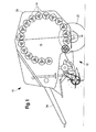
- a round baler 10 which includes a chassis 12 and in this rotatably mounted rollers 14.
- the rollers 14 are located in the peripheral region of a pressing space 16 and are provided with one or more support devices 18 (FIG. 2).
- the round baler 10 is formed in the embodiment shown as a constant-sized pressing chamber 16; this is not mandatory - it may also be a round baler 10 with a variable in size pressing chamber 16.
- the chassis 12 is formed as usual and has side walls 20 which laterally cover the pressing space 16 and rotatably receive the rollers 14. Wheels 22 and a drawbar 24 are provided on the chassis 12 and make it possible to pull the round baler 10 behind a towing vehicle, not shown.
- roller 14 there may be several or even a single roller 14 are provided, each having a tube 26, stub shaft 28 and one or more support devices 18. Each roller 14 is rotatable about a longitudinal center axis which extends horizontally and transversely to the direction of travel.
- the tube 26 is formed of sheet steel, has a smooth, profiled or equipped with drivers outer surface and is formed either pulled or welded.
- the stub shafts 28 are - even if only shown on one side - inserted into the tube 26 by means of a hub 30 and The hub 30 and the stub shaft 28 can also be screwed to a web, not shown, in the pipe 26 or through a through the entire pipe 26 therethrough extending shaft or axis are replaced.
- the pressing space 16 is adapted to receive a round bale, not shown, which may have a weight of almost 1000 kg, especially in silage.
- a roller 14 is arranged in the lower region of the pressing space 16, this weight rests on the roller 14 and leads to a high radial load on the tube 26.
- the support device 18 is implemented as an assembly which is axially inserted into the tube 26, positioned and pressed against the inner surface of the tube 26.
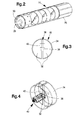
- the supporting device 18 shown in FIGS. 2 to 4 contains two webs 32 and a band 34.
- the webs 32 are formed of steel and extend in the installed state radially to the longitudinal center axis of the tube 26.
- the webs 32 have a design that is sufficient to support the forces acting on the tube 26 from the outside.
- Between the webs 32 there is a recess 36 or a gap whose function will be explained later.
- the webs 32 essentially cover the cross section of the tube 26.
- abutment surfaces 38 are provided which can be acted upon by a spreading device 40 (see Fig. 4), as will be described later.
- These contact surfaces 38 are preferably slightly bevelled to form a kind of inclined plane.
- the band 34 is also formed of steel and is centrally placed in this embodiment on the webs 32 and welded to these on its inside.
- the band 34 is at a location coincident with the location of the recess 36, interrupted.
- the outer shape of the band 34 follows the inner shape of the tube 26.
- the band 34 forms with the webs 32 a structural unit which can be spread in the open region of the recess 36, which means that the band 34 in the closed region of the recess 36th is slightly bent.
- the spreading device 40 is formed in the simplest form as a wedge, which can be moved by means of a threaded connection, with hammer blow or the like in the axial direction of the tube 26.
- the spreading device 40 preferably also has contact surfaces 38, which can be brought into operative connection with the abutment surfaces 38 on the webs 32. Due to the slope of the contact surfaces 38 and the relative movement between the spreading device 40 and the webs 32, there is a movement component of the webs 32 in the radial direction when the spreading device 40 is moved.
- a bridge part 42 also belongs to the support device 18, however, is mounted only in the assembled state of the support device 18.
- the bridge part 42 is a simple steel strap, which is welded to one of the webs 32 at both ends and thus holds the support device 18 in its spread position.
- FIG. 5 a second embodiment of the invention is shown, in which the support device 18 includes two half-shell-like support members 44 and the spreading device 40 includes a screw 46.
- Each support member 44 has a web 32 and a band 34 corresponding half-shell 48, wherein the respective web 32 is welded into the concave interior of the half-shell 48.
- Each half-shell 48 terminates in proximate axially-extending end edges 50 which have a slight inclination in the direction of the longitudinal center axis of the roller 14.
- the end edges 50 of two adjacent half-shells 48 coincide in the assembled state in a plane and form part of the spreading device 40.
- the webs 32 are each in the half of the respective half-shell 48, in which there is their larger radians.
- each web 32 has a recess 36 in the form of a bore or a slot which at least substantially coincide in the mounted state of the support device 18 and through which the screw 46 extends.
- a head or hook of the screw 46 abuts the outer surface of one web 32 and a nut on an outer surface of the other web 32, so that when the nut is tightened, the two webs 32 and with them the half shells 48 are pulled together ,
- the half-shells 48 like the band 34, are sized and configured to abut the inner surface of the tube 26 and to support it inwardly.
- the support device 18 is inserted either as a preassembled unit or in parts in the tube 26, so that the half shells 48 come to lie with their end edges 50 to each other, and the screw 40 and the nut mounted or tightened until the half-shells 48 completely to the Inner surface of the tube 26 are pressed. In this position, either the screw 40 is secured or a bridge part 42 is welded over the two half shells 48, so that they remain in the spread position of the support device 18.
- the half-shells 48 are formed in the axial direction longer than the band 34 - but this is not mandatory and depends on the size and nature of the expected load.
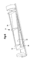
- FIG. 6 again shows another exemplary embodiment of the invention, in which the support device 18 now contains two web supports 52, which carry a plurality of - in this case three - radially aligned webs 32 (screwed or welded) on a plate 54 and extend over a considerable section of the tube 26 extend.
- the webs 32 have sequentially increasing radial dimensions, so that in the assembled state, the plates 54 occupy an inclined to the longitudinal center axis of the roller 14 position.
- the two web support 52 in the tube 26 are the plates 54, as already the end edges 50 according to the embodiment in Figure 5, on contact surfaces 38 on each other.
- the two formed as a web support 52 support members 44 are not clamped by a screw or the like, but driven by blows on each other.
- the webs 32 can by means of a strut 56 are interconnected to stabilize the structure.
- the two web support 52 can in turn be connected and locked together by means of a bridge part 42, not shown.
- FIG. 7 a further embodiment of a support device 18 is shown in Figure 7, in which two pairs of webs 32 are arranged in mirror image radially about a spreading device 40 and held in the axial direction of a sleeve 58 at a distance.
- Each ridge 32 extends slightly less than half of the cross-section of the tube 26 and has an outer edge which follows the inner surface of the tube 26 and can be firmly attached to this.
- a contact surface 38 which extends slightly inclined to the longitudinal center axis of the roller 14. This contact surface 38 may be formed flat or bounded by side walls and extends in this embodiment in the axial direction on both sides beyond the webs 32 addition.
- the sleeve 58 is round cylindrical and hollow and coincides with the web surfaces, so that they can be supported on the webs 32 in the installed state.
- a spreading device 40 in turn includes a screw 46, are pushed onto the two symmetrical wedges 60.
- the wedges 60 have contact surfaces 38 which can be applied to the congruently formed and arranged bearing surfaces 38 on the webs 32.
- This support device 18 is assembled as an assembly outside of the tube 26, which is done by sliding the two wedges 60 symmetrically onto the screw 40 and securing them by means of a nut that the sleeve 58 is slid over the middle section of the screw 40 the webs 32 are placed on the wedges 60 to form a disc and finally the nut is tightened, so that the webs 32 bear against the end surfaces of the sleeve 58 and held sufficiently strong for mounting purposes. Subsequently, the support device 18 is inserted into the tube 26 and the nut tightened further, so that the webs 32 move radially outward and the tube 26 are supported inside.
Landscapes
- Life Sciences & Earth Sciences (AREA)
- Environmental Sciences (AREA)
- Engineering & Computer Science (AREA)
- Mechanical Engineering (AREA)
- Rolls And Other Rotary Bodies (AREA)
- Packaging Of Machine Parts And Wound Products (AREA)
- Mutual Connection Of Rods And Tubes (AREA)
Priority Applications (1)
| Application Number | Priority Date | Filing Date | Title |
|---|---|---|---|
| PL07103033T PL1834518T3 (pl) | 2006-03-15 | 2007-02-26 | Urządzenie wsporcze dla rolki, w szczególności prasy do bel okrągłych, oraz sposób wytwarzania takiej rolki |
Applications Claiming Priority (1)
| Application Number | Priority Date | Filing Date | Title |
|---|---|---|---|
| DE102006011777A DE102006011777B4 (de) | 2006-03-15 | 2006-03-15 | Stützvorrichtung für eine Rolle, insbesondere einer Rundballenpresse, und Verfahren zum Herstellen einer solchen Rolle |
Publications (2)
| Publication Number | Publication Date |
|---|---|
| EP1834518A1 true EP1834518A1 (fr) | 2007-09-19 |
| EP1834518B1 EP1834518B1 (fr) | 2013-05-15 |
Family
ID=38037445
Family Applications (1)
| Application Number | Title | Priority Date | Filing Date |
|---|---|---|---|
| EP07103033.2A Not-in-force EP1834518B1 (fr) | 2006-03-15 | 2007-02-26 | Dispositif de support pour un rouleau, en particulier une presse à balles rondes, et procédé de fabrication d'un tel rouleau |
Country Status (3)
| Country | Link |
|---|---|
| EP (1) | EP1834518B1 (fr) |
| DE (1) | DE102006011777B4 (fr) |
| PL (1) | PL1834518T3 (fr) |
Cited By (3)
| Publication number | Priority date | Publication date | Assignee | Title |
|---|---|---|---|---|
| EP2537408A1 (fr) * | 2011-06-21 | 2012-12-26 | Usines Claas France S.A.S | Rouleau pour une presse à bales agricole |
| CN106134640A (zh) * | 2015-04-24 | 2016-11-23 | 呼伦贝尔市蒙力农牧业机械制造有限公司 | 一种圆草捆打捆机的成捆室 |
| EP3461325A1 (fr) * | 2017-09-27 | 2019-04-03 | Usines Claas France S.A.S | Rouleau pour une presse à balles agricole |
Citations (6)
| Publication number | Priority date | Publication date | Assignee | Title |
|---|---|---|---|---|
| US3900913A (en) | 1974-04-01 | 1975-08-26 | Arthur E Drumm | Core mounting assembly for rotary brooms |
| US4198804A (en) * | 1978-08-08 | 1980-04-22 | Gebr. Claas Maschinenfabrik Gmbh | Round baler machine |
| DE3010607A1 (de) * | 1976-02-11 | 1981-09-24 | Clouth Gummiwerke AG, 5000 Köln | Tragrolle fuer foerdergurte |
| DE3205609A1 (de) | 1982-02-17 | 1983-08-25 | Clouth Gummiwerke AG, 5000 Köln | "tragrolle fuer foerdergurte" |
| GB2241558A (en) * | 1989-06-27 | 1991-09-04 | James Murphy | A conveyor roller |
| DE19907290C1 (de) | 1999-02-22 | 2000-05-25 | Claas Usines France | Walze für Erntemaschinen |
Family Cites Families (3)
| Publication number | Priority date | Publication date | Assignee | Title |
|---|---|---|---|---|
| AT193336B (de) * | 1956-06-19 | 1957-11-25 | Ver Farbereien Aktien Ges | Aufspannvorrichtung für Zylindermäntel oder Walzenbezüge, insbesondere für den Textildruck |
| DE3940744C2 (de) * | 1989-12-09 | 1994-03-17 | Hansmann Erich Dipl Ing | Walze für eine Vorrichtung zum Bearbeiten von bahn- oder tafelförmigem Material |
| DE10100403A1 (de) * | 2001-01-05 | 2002-07-11 | Entro Systeme Fuer Den Bau Gmb | Verbinder für zylindrische Rohre, insbesondere Handlaufabschnitte |
-
2006
- 2006-03-15 DE DE102006011777A patent/DE102006011777B4/de not_active Expired - Fee Related
-
2007
- 2007-02-26 EP EP07103033.2A patent/EP1834518B1/fr not_active Not-in-force
- 2007-02-26 PL PL07103033T patent/PL1834518T3/pl unknown
Patent Citations (6)
| Publication number | Priority date | Publication date | Assignee | Title |
|---|---|---|---|---|
| US3900913A (en) | 1974-04-01 | 1975-08-26 | Arthur E Drumm | Core mounting assembly for rotary brooms |
| DE3010607A1 (de) * | 1976-02-11 | 1981-09-24 | Clouth Gummiwerke AG, 5000 Köln | Tragrolle fuer foerdergurte |
| US4198804A (en) * | 1978-08-08 | 1980-04-22 | Gebr. Claas Maschinenfabrik Gmbh | Round baler machine |
| DE3205609A1 (de) | 1982-02-17 | 1983-08-25 | Clouth Gummiwerke AG, 5000 Köln | "tragrolle fuer foerdergurte" |
| GB2241558A (en) * | 1989-06-27 | 1991-09-04 | James Murphy | A conveyor roller |
| DE19907290C1 (de) | 1999-02-22 | 2000-05-25 | Claas Usines France | Walze für Erntemaschinen |
Cited By (3)
| Publication number | Priority date | Publication date | Assignee | Title |
|---|---|---|---|---|
| EP2537408A1 (fr) * | 2011-06-21 | 2012-12-26 | Usines Claas France S.A.S | Rouleau pour une presse à bales agricole |
| CN106134640A (zh) * | 2015-04-24 | 2016-11-23 | 呼伦贝尔市蒙力农牧业机械制造有限公司 | 一种圆草捆打捆机的成捆室 |
| EP3461325A1 (fr) * | 2017-09-27 | 2019-04-03 | Usines Claas France S.A.S | Rouleau pour une presse à balles agricole |
Also Published As
| Publication number | Publication date |
|---|---|
| EP1834518B1 (fr) | 2013-05-15 |
| DE102006011777A1 (de) | 2007-10-04 |
| DE102006011777B4 (de) | 2013-11-28 |
| PL1834518T3 (pl) | 2013-10-31 |
Similar Documents
| Publication | Publication Date | Title |
|---|---|---|
| EP1853408B1 (fr) | Dispositif et procede pour etablir un assemblage par vis entre un premier element constitutif et au moins un autre element constitutif | |
| EP0175856B1 (fr) | Collier de serrage avec vis tendeuse | |
| DE2938476C3 (de) | Verfahren zur Herstellung einer Verbindung von zwei mit Flanschen versehenen Wellenstümpfen und Wellenkupplung nach diesem Verfahren | |
| DE9216369U1 (de) | Preßwerkzeug | |
| DE3536696A1 (de) | Klemmvorrichtung | |
| EP0616162A1 (fr) | Anneau de bride pouvant être monté sur un tuyau en tôle à paroi mince et son procédé de fabrication | |
| DE102015001092A1 (de) | Planenaufhängvorrichtung | |
| DE60005763T2 (de) | Biegepresse mit Unterbalken versehen mit Schlitzen | |
| DE60014889T2 (de) | Verfahren und vorrichtung zum verschweissen von länglichen elementen | |
| EP1834518B1 (fr) | Dispositif de support pour un rouleau, en particulier une presse à balles rondes, et procédé de fabrication d'un tel rouleau | |
| DE1552087B2 (de) | Rollkopf zum Aufweiten von Rohren mit entsprechend der Rohrwandungskrümmung ballig ausgebildeten Rollen | |
| CH705267A2 (de) | Vorrichtung zum Befestigen eines Zugelementes, insbesondere eines Zugseils. | |
| DE2007400C3 (de) | Vorrichtung zum Herstellen von Wärmetauscherelementen | |
| DE1774749A1 (de) | Aufweitbarer Wickeldorn | |
| DE60202282T2 (de) | Klemmspaltmutter | |
| DE2724891A1 (de) | Mehrteilige klemmverbindung | |
| EP1412117A1 (fr) | Element d'ecartement pour une pince de serrage et pince de serrage | |
| EP0953385B1 (fr) | Machine pour le dressage des poutres laminées | |
| DE2611175C3 (de) | Schlauchbefestigungsvorrichtung | |
| CH636933A5 (en) | Device for attaching an element to a pipe | |
| DE19504401C1 (de) | Verfahren zum Einstellen des Lagerspiels von Wälzlagern mit hydraulischen Spannmuttern oder Lagereinstellringen | |
| DE2515166C2 (de) | Spannverbindung fuer ineinander liegende enden bodenabgestuetzter rinnenprofile von grubenausbaurahmen | |
| EP2803533B1 (fr) | Dispositif destiné à agencer une barre présentant un canal longitudinal sur un support | |
| DE202008007955U1 (de) | Anordnung zum Verbinden zweier gleichartiger Laufschienen | |
| WO1996021531A1 (fr) | Procede pour raccorder un raccord emmanche a une extremite de tuyau et presse pour la mise en ×uvre de ce procede |
Legal Events
| Date | Code | Title | Description |
|---|---|---|---|
| PUAI | Public reference made under article 153(3) epc to a published international application that has entered the european phase |
Free format text: ORIGINAL CODE: 0009012 |
|
| AK | Designated contracting states |
Kind code of ref document: A1 Designated state(s): AT BE BG CH CY CZ DE DK EE ES FI FR GB GR HU IE IS IT LI LT LU LV MC NL PL PT RO SE SI SK TR |
|
| AX | Request for extension of the european patent |
Extension state: AL BA HR MK YU |
|
| RIN1 | Information on inventor provided before grant (corrected) |
Inventor name: BARROT, LAURENT Inventor name: RINGENBACH, GILLES Inventor name: BONFILS, PIERRE-ALEXANDRE |
|
| 17P | Request for examination filed |
Effective date: 20080319 |
|
| 17Q | First examination report despatched |
Effective date: 20080424 |
|
| AKX | Designation fees paid |
Designated state(s): AT BE BG CH CY CZ DE DK EE ES FI FR GB GR HU IE IS IT LI LT LU LV MC NL PL PT RO SE SI SK TR |
|
| REG | Reference to a national code |
Ref country code: DE Ref legal event code: R079 Ref document number: 502007011750 Country of ref document: DE Free format text: PREVIOUS MAIN CLASS: A01F0015080000 Ipc: A01F0015180000 |
|
| GRAP | Despatch of communication of intention to grant a patent |
Free format text: ORIGINAL CODE: EPIDOSNIGR1 |
|
| RIC1 | Information provided on ipc code assigned before grant |
Ipc: B65G 39/02 20060101ALI20121207BHEP Ipc: A01F 15/18 20060101AFI20121207BHEP |
|
| RIN1 | Information on inventor provided before grant (corrected) |
Inventor name: BONFILS, PIERRE-ALEXANDRE Inventor name: BARROT, LAURENT Inventor name: RINGENBACH, GILLES |
|
| GRAS | Grant fee paid |
Free format text: ORIGINAL CODE: EPIDOSNIGR3 |
|
| GRAA | (expected) grant |
Free format text: ORIGINAL CODE: 0009210 |
|
| AK | Designated contracting states |
Kind code of ref document: B1 Designated state(s): AT BE BG CH CY CZ DE DK EE ES FI FR GB GR HU IE IS IT LI LT LU LV MC NL PL PT RO SE SI SK TR |
|
| REG | Reference to a national code |
Ref country code: GB Ref legal event code: FG4D Free format text: NOT ENGLISH Ref country code: CH Ref legal event code: EP |
|
| REG | Reference to a national code |
Ref country code: AT Ref legal event code: REF Ref document number: 611629 Country of ref document: AT Kind code of ref document: T Effective date: 20130615 |
|
| REG | Reference to a national code |
Ref country code: IE Ref legal event code: FG4D Free format text: LANGUAGE OF EP DOCUMENT: GERMAN |
|
| REG | Reference to a national code |
Ref country code: DE Ref legal event code: R096 Ref document number: 502007011750 Country of ref document: DE Effective date: 20130711 |
|
| REG | Reference to a national code |
Ref country code: NL Ref legal event code: T3 |
|
| REG | Reference to a national code |
Ref country code: LT Ref legal event code: MG4D |
|
| PG25 | Lapsed in a contracting state [announced via postgrant information from national office to epo] |
Ref country code: ES Free format text: LAPSE BECAUSE OF FAILURE TO SUBMIT A TRANSLATION OF THE DESCRIPTION OR TO PAY THE FEE WITHIN THE PRESCRIBED TIME-LIMIT Effective date: 20130826 Ref country code: SE Free format text: LAPSE BECAUSE OF FAILURE TO SUBMIT A TRANSLATION OF THE DESCRIPTION OR TO PAY THE FEE WITHIN THE PRESCRIBED TIME-LIMIT Effective date: 20130515 Ref country code: SI Free format text: LAPSE BECAUSE OF FAILURE TO SUBMIT A TRANSLATION OF THE DESCRIPTION OR TO PAY THE FEE WITHIN THE PRESCRIBED TIME-LIMIT Effective date: 20130515 Ref country code: PT Free format text: LAPSE BECAUSE OF FAILURE TO SUBMIT A TRANSLATION OF THE DESCRIPTION OR TO PAY THE FEE WITHIN THE PRESCRIBED TIME-LIMIT Effective date: 20130916 Ref country code: GR Free format text: LAPSE BECAUSE OF FAILURE TO SUBMIT A TRANSLATION OF THE DESCRIPTION OR TO PAY THE FEE WITHIN THE PRESCRIBED TIME-LIMIT Effective date: 20130816 Ref country code: FI Free format text: LAPSE BECAUSE OF FAILURE TO SUBMIT A TRANSLATION OF THE DESCRIPTION OR TO PAY THE FEE WITHIN THE PRESCRIBED TIME-LIMIT Effective date: 20130515 Ref country code: IS Free format text: LAPSE BECAUSE OF FAILURE TO SUBMIT A TRANSLATION OF THE DESCRIPTION OR TO PAY THE FEE WITHIN THE PRESCRIBED TIME-LIMIT Effective date: 20130915 Ref country code: LT Free format text: LAPSE BECAUSE OF FAILURE TO SUBMIT A TRANSLATION OF THE DESCRIPTION OR TO PAY THE FEE WITHIN THE PRESCRIBED TIME-LIMIT Effective date: 20130515 |
|
| REG | Reference to a national code |
Ref country code: PL Ref legal event code: T3 |
|
| PG25 | Lapsed in a contracting state [announced via postgrant information from national office to epo] |
Ref country code: BG Free format text: LAPSE BECAUSE OF FAILURE TO SUBMIT A TRANSLATION OF THE DESCRIPTION OR TO PAY THE FEE WITHIN THE PRESCRIBED TIME-LIMIT Effective date: 20130815 |
|
| PG25 | Lapsed in a contracting state [announced via postgrant information from national office to epo] |
Ref country code: LV Free format text: LAPSE BECAUSE OF FAILURE TO SUBMIT A TRANSLATION OF THE DESCRIPTION OR TO PAY THE FEE WITHIN THE PRESCRIBED TIME-LIMIT Effective date: 20130515 |
|
| PG25 | Lapsed in a contracting state [announced via postgrant information from national office to epo] |
Ref country code: SK Free format text: LAPSE BECAUSE OF FAILURE TO SUBMIT A TRANSLATION OF THE DESCRIPTION OR TO PAY THE FEE WITHIN THE PRESCRIBED TIME-LIMIT Effective date: 20130515 Ref country code: CZ Free format text: LAPSE BECAUSE OF FAILURE TO SUBMIT A TRANSLATION OF THE DESCRIPTION OR TO PAY THE FEE WITHIN THE PRESCRIBED TIME-LIMIT Effective date: 20130515 Ref country code: DK Free format text: LAPSE BECAUSE OF FAILURE TO SUBMIT A TRANSLATION OF THE DESCRIPTION OR TO PAY THE FEE WITHIN THE PRESCRIBED TIME-LIMIT Effective date: 20130515 Ref country code: EE Free format text: LAPSE BECAUSE OF FAILURE TO SUBMIT A TRANSLATION OF THE DESCRIPTION OR TO PAY THE FEE WITHIN THE PRESCRIBED TIME-LIMIT Effective date: 20130515 |
|
| PG25 | Lapsed in a contracting state [announced via postgrant information from national office to epo] |
Ref country code: RO Free format text: LAPSE BECAUSE OF FAILURE TO SUBMIT A TRANSLATION OF THE DESCRIPTION OR TO PAY THE FEE WITHIN THE PRESCRIBED TIME-LIMIT Effective date: 20130515 |
|
| PLBE | No opposition filed within time limit |
Free format text: ORIGINAL CODE: 0009261 |
|
| STAA | Information on the status of an ep patent application or granted ep patent |
Free format text: STATUS: NO OPPOSITION FILED WITHIN TIME LIMIT |
|
| 26N | No opposition filed |
Effective date: 20140218 |
|
| PGFP | Annual fee paid to national office [announced via postgrant information from national office to epo] |
Ref country code: NL Payment date: 20140226 Year of fee payment: 8 Ref country code: DE Payment date: 20140121 Year of fee payment: 8 Ref country code: IE Payment date: 20140227 Year of fee payment: 8 |
|
| REG | Reference to a national code |
Ref country code: DE Ref legal event code: R097 Ref document number: 502007011750 Country of ref document: DE Effective date: 20140218 |
|
| PGFP | Annual fee paid to national office [announced via postgrant information from national office to epo] |
Ref country code: FR Payment date: 20140220 Year of fee payment: 8 Ref country code: IT Payment date: 20140224 Year of fee payment: 8 |
|
| BERE | Be: lapsed |
Owner name: DEERE & CY Effective date: 20140228 |
|
| PG25 | Lapsed in a contracting state [announced via postgrant information from national office to epo] |
Ref country code: MC Free format text: LAPSE BECAUSE OF FAILURE TO SUBMIT A TRANSLATION OF THE DESCRIPTION OR TO PAY THE FEE WITHIN THE PRESCRIBED TIME-LIMIT Effective date: 20130515 Ref country code: LU Free format text: LAPSE BECAUSE OF FAILURE TO SUBMIT A TRANSLATION OF THE DESCRIPTION OR TO PAY THE FEE WITHIN THE PRESCRIBED TIME-LIMIT Effective date: 20140226 |
|
| REG | Reference to a national code |
Ref country code: CH Ref legal event code: PL |
|
| GBPC | Gb: european patent ceased through non-payment of renewal fee |
Effective date: 20140226 |
|
| PG25 | Lapsed in a contracting state [announced via postgrant information from national office to epo] |
Ref country code: CH Free format text: LAPSE BECAUSE OF NON-PAYMENT OF DUE FEES Effective date: 20140228 Ref country code: LI Free format text: LAPSE BECAUSE OF NON-PAYMENT OF DUE FEES Effective date: 20140228 |
|
| PG25 | Lapsed in a contracting state [announced via postgrant information from national office to epo] |
Ref country code: BE Free format text: LAPSE BECAUSE OF NON-PAYMENT OF DUE FEES Effective date: 20140228 Ref country code: GB Free format text: LAPSE BECAUSE OF NON-PAYMENT OF DUE FEES Effective date: 20140226 |
|
| REG | Reference to a national code |
Ref country code: AT Ref legal event code: MM01 Ref document number: 611629 Country of ref document: AT Kind code of ref document: T Effective date: 20140226 |
|
| PG25 | Lapsed in a contracting state [announced via postgrant information from national office to epo] |
Ref country code: AT Free format text: LAPSE BECAUSE OF NON-PAYMENT OF DUE FEES Effective date: 20140226 |
|
| REG | Reference to a national code |
Ref country code: DE Ref legal event code: R119 Ref document number: 502007011750 Country of ref document: DE |
|
| REG | Reference to a national code |
Ref country code: NL Ref legal event code: V1 Effective date: 20150901 |
|
| PG25 | Lapsed in a contracting state [announced via postgrant information from national office to epo] |
Ref country code: NL Free format text: LAPSE BECAUSE OF NON-PAYMENT OF DUE FEES Effective date: 20150901 |
|
| REG | Reference to a national code |
Ref country code: IE Ref legal event code: MM4A |
|
| REG | Reference to a national code |
Ref country code: FR Ref legal event code: ST Effective date: 20151030 |
|
| PG25 | Lapsed in a contracting state [announced via postgrant information from national office to epo] |
Ref country code: IT Free format text: LAPSE BECAUSE OF NON-PAYMENT OF DUE FEES Effective date: 20150226 |
|
| PG25 | Lapsed in a contracting state [announced via postgrant information from national office to epo] |
Ref country code: IE Free format text: LAPSE BECAUSE OF NON-PAYMENT OF DUE FEES Effective date: 20150226 Ref country code: DE Free format text: LAPSE BECAUSE OF NON-PAYMENT OF DUE FEES Effective date: 20150901 |
|
| PG25 | Lapsed in a contracting state [announced via postgrant information from national office to epo] |
Ref country code: FR Free format text: LAPSE BECAUSE OF NON-PAYMENT OF DUE FEES Effective date: 20150302 |
|
| PG25 | Lapsed in a contracting state [announced via postgrant information from national office to epo] |
Ref country code: CY Free format text: LAPSE BECAUSE OF FAILURE TO SUBMIT A TRANSLATION OF THE DESCRIPTION OR TO PAY THE FEE WITHIN THE PRESCRIBED TIME-LIMIT Effective date: 20130515 |
|
| PG25 | Lapsed in a contracting state [announced via postgrant information from national office to epo] |
Ref country code: TR Free format text: LAPSE BECAUSE OF FAILURE TO SUBMIT A TRANSLATION OF THE DESCRIPTION OR TO PAY THE FEE WITHIN THE PRESCRIBED TIME-LIMIT Effective date: 20130515 Ref country code: HU Free format text: LAPSE BECAUSE OF FAILURE TO SUBMIT A TRANSLATION OF THE DESCRIPTION OR TO PAY THE FEE WITHIN THE PRESCRIBED TIME-LIMIT; INVALID AB INITIO Effective date: 20070226 |
|
| PGFP | Annual fee paid to national office [announced via postgrant information from national office to epo] |
Ref country code: PL Payment date: 20220202 Year of fee payment: 16 |
|
| PG25 | Lapsed in a contracting state [announced via postgrant information from national office to epo] |
Ref country code: PL Free format text: LAPSE BECAUSE OF NON-PAYMENT OF DUE FEES Effective date: 20230226 |
|
| PG25 | Lapsed in a contracting state [announced via postgrant information from national office to epo] |
Ref country code: PL Free format text: LAPSE BECAUSE OF NON-PAYMENT OF DUE FEES Effective date: 20230226 |