EP1834526B1 - Vorrichtung zum Aufnehmen von Innereien - Google Patents
Vorrichtung zum Aufnehmen von Innereien Download PDFInfo
- Publication number
- EP1834526B1 EP1834526B1 EP07075198A EP07075198A EP1834526B1 EP 1834526 B1 EP1834526 B1 EP 1834526B1 EP 07075198 A EP07075198 A EP 07075198A EP 07075198 A EP07075198 A EP 07075198A EP 1834526 B1 EP1834526 B1 EP 1834526B1
- Authority
- EP
- European Patent Office
- Prior art keywords
- retainers
- shielders
- packages
- conveyor
- carcasses
- Prior art date
- Legal status (The legal status is an assumption and is not a legal conclusion. Google has not performed a legal analysis and makes no representation as to the accuracy of the status listed.)
- Not-in-force
Links
Images


Classifications
-
- A—HUMAN NECESSITIES
- A22—BUTCHERING; MEAT TREATMENT; PROCESSING POULTRY OR FISH
- A22C—PROCESSING MEAT, POULTRY, OR FISH
- A22C21/00—Processing poultry
- A22C21/06—Eviscerating devices for poultry
Definitions
- the invention relates to a device and a method for taking packages of entrails of eviscerated small live stock carcasses, particularly poultry.
- Removing the packages of entrails of poultry carcasses can take place more or less immediately subsequent to eviscerating the carcasses, by also severing the gullet to which the entrails are attached. This requires an eviscerating tool of a complex structure.
- the gullet is severed by means of a tool inserted into the carcass cavity after evisceration, after which the entrails package is separate from the carcass. This requires an additional tool.
- a device for removing entrails from a carcass in which a pulling element is inserted into the carcass to eviscerate the entrails from the carcass.
- a clamping element comprising a U-shaped bar having side elements and a rotatable clamping bar ensures that a part of the gullet is fixedly clamped between the clamping bar and a side element when the entrails have been eviscerated from the carcass by the pulling element.
- the entrails are pulled away from of the carcass by moving the carcass holder (suspended from a conveyor path) and the clamping element (arranged on a carrousel) apart.
- the clamping bar and the side element extend radially from the carrousel, so that in case of (radial) moving apart of the carcass and the clamping element with entrails fixedly clamped in between them (by clamping forces oriented tangential to the carrousel), the entrails may slide from between the clamping bar and the side elements, and pulling loose might take place in a less defined manner.
- the invention provides a device for separating carcasses of small live stock animals from the packages of entrails eviscerated from the carcasses and connected thereto by the gullet, comprising a first conveyor provided with respective holders for the carcasses for transportation in series of the carcasses according to a first path, and a second conveyor provided with a series of shielders/retainers for shielding/retaining the packages from the carcasses held by the holders, wherein the second conveyor is positioned for movement according to a second path having a first track going up together with the first conveyor, wherein the packages can be engaged by the shielders/retainers, and a subsequent second track, diverging from the first path, for increasing the distance between the carcasses and the related packages to pull the gullet loose or rupture it, wherein the shielders/retainers are adapted for discharging the released packages.
- the gullet can thus automatically, by engagement outside of the carcass, be ruptured or pulled loose.
- the capacity may be high here, whereas personnel is economised on.
- the rupturing of the gullet can be established immediately.
- the shielders/retainers are designed such that the shielding/retaining force exerted on the packages by the shielders/retainers is contrary to a direction of divergence of the second track and the first path.
- pulling loose can take place in a highly defined way without the entrails being able to slide from the shielders/retainers.
- the shielders/retainers have been provided in particular with an element for engaging the packages, which element is positioned transverse to the direction of divergence.
- the device is furthermore provided with means for, between the carcass and the package of entrails, forming a stop for a piece of entrails connected to the gullet, which stop moves along with the second path, thus enhancing the rupturing. Because the gullet is still connected to the carcass cavity the package will be tugged when the package is moved away. The package will therefore move against the stop, until an obstacle in the form of the muscular stomach abuts the edge.
- the transitional area from gullet to gizzard is relatively weak, as a result of which the gullet will easily rupture at that location. This also applies to the attachment of the gizzard to the muscular stomach as a result of which the separation can also take place there.
- Rupturing is further enhanced when the shielders/retainers have been provided with a thickened edge for the gullet, which edge preferably also forms the stop.
- Discharging the packages is enhanced when the shielders/retainers form a holder having a substantially vertical passage.
- Discharging can further be controlled when the holders have been provided with a movable bottom wall that is movable between a package support position and a package passage position. In said latter position the packages can be discharged at a selected place.
- the second conveyor may have been provided with means for moving the shielders/retainers up and down, between a lowered position free from a package and a lifted position in which a package has been picked up.
- the shielders/retainers may comprise first and second shielders/retainers, that are movable towards each other in order to form a narrowing for an organ of the packages in an operative position in mutual cooperation.
- the first shielders/retainers can be moved upward to the operative position, and the second shielders/retainers can be moved downward.
- the second shielders/retainers may extend up to the first shielders/retainers, particularly a stop edge thereof, while leaving the narrowing open for improved confinement of the package.
- the second shielders/retainers may with a stop edge extend over the first shielders/retainers, particularly a stop edge thereof, in order to offer a stop for the muscular stomach also in cases where the muscular stomach is situated a little closer to the carcass, such as between the legs, where a stop edge on the first shielder/retainer is unable to reach or only with a lot of difficulty.
- the engagement of a muscular stomach situated between the legs is enhanced when the stop edge of the second shielders/retainers extending over the first shielders/retainers is positioned for a rotary or swinging motion from above in the direction of the first shielders/retainers.
- the stop edge of the second shielders/retainers extending over first shielders/retainers may for that purpose be positioned for a substantially horizontal rotary or swinging motion in the direction of the first shielders/retainers.
- the muscular stomach may then be urged away from between the legs in the direction of the first shielders/retainers.
- the device has furthermore been provided with a third conveyor for transportation of separated packages, wherein the shielders/retainers are adapted for discharging the packages to the third conveyor during movement according to the second track.
- the packages are then discharged and transported away almost immediately after detachment or rupture of the gullet.
- the third conveyor may be situated below at least a part of the second track and below a discharge track of the first conveyor downstream of the start of the second track.
- the start of the second track and the start of the discharge track of the first conveyor may then be spaced apart.
- the discharge of the packages can then take place parallel to the discharge of the carcasses so that the occupation of space can remain within limits.
- the first conveyor may be an overhead conveyor.
- the second conveyor may be a carrousel on which the shielders/retainers have been arranged.
- the third conveyor may be a belt conveyor.
- the second path is circulating about one or several vertical centre lines, preferably according to a circular path.
- the invention provides a device for separating carcasses of small live stock animals from the packages of entrails eviscerated from the carcasses and connected thereto by the gullet, comprising a first conveyor provided with respective holders for the carcasses for transportation in series of the carcasses according to a first path, and a second conveyor provided with a series of pickers or confiners for picking up the packages from the carcasses held by the holders, wherein the second conveyor is positioned for movement according to a second path having a first track going up together with the first conveyor, wherein the packages can be picked up by the pickers, and a subsequent second track, diverging from the first path, for increasing the distance between the carcasses and the related packages to pull the gullet loose or rupture it, wherein the pickers are adapted for discharging the released packages.
- the invention provides a method for separating carcasses of small live stock animals from the packages of entrails eviscerated from the carcasses and connected thereto by the gullet, wherein the carcasses are transported in series according to a first path wherein shielders/retainers or package pickers that move along, are moved between the carcasses and the related packages, after which the packages according to a second path followed by the shielders/retainers and diverging from the first path followed by the carcasses are diverted from carcasses following the first path in order to detach or rupture the gullet, after which the packages are collected for discharge.
- the shielders/retainers in particular exert a force on the packages that is contrary to the direction of divergence of the first and second path.
- the entrails are retained by a stop for that purpose in order to move to the carcass.
- the gullet is ruptured near the stomach, particularly near the transition of the gullet to the gizzard, or detached by rupture between gizzard and muscular stomach.
- the packages are engaged by holder moving upward which are subsequently moved away from the carcasses in horizontal direction.
- a valve or the like that can be moved between a position holding the package up and a position releasing the package.
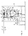
- FIG 1 schematically shows an overhead conveyor 10, which, also see figure 2 , is adapted for overhead transportation of carcasses, in the manner known per se, wherein for instance by means of a chain trolleys 12 connected to each other are moved over/along a tube 11.
- the trolleys 1 2 have been provided with brackets 1 3 in which the legs of the carcasses can be hung.
- the carcasses come from the direction A, the track 10a, from an evisceration station, not shown, where the packages of entrails have been eviscerated from the carcasses.
- the packages of entrails are still connected to the carcass cavity via the gullet, wherein the packages of entrails hang down beside the carcass.
- the track 10a changes into semicircular track 10b, circulating with a package separation device 20 in an exemplary embodiment of the invention.
- the track 10b bends away from the device 20 in track 10c, and changes into a straight track 10d.
- a discharge conveyor 30 having a conveyor belt 31 is situated below the straight track 10d. At the end of the conveyor 30 the overhead conveyor 10 bends away into track 10e.
- the device 20 further shown in figures 2 and further, comprises a carrousel rotated by said chain in direction B via chain wheel 100 (left out in figure 1 ) bearing-mounted at the location of 24a on axle 21 permanent to the frame 25.
- the carrousel comprises an upper plate wheel 102 and a lower plate wheel 103 which at the location of 24b and 24c are bearing-mounted on the permanent axle 21.
- a drum 22 has been arranged on the permanent axle 21, which drum has been provided with circulating curve tracks 26 and 27.
- the curve tracks 26 and 27 have been arranged for vertical movement, in a controlled manner, of a first shielder/retainer or lower unit 28 and a second shielder/retainer or upper unit 29, which have been arranged so as to be vertically slidable on rods 33, which themselves have been attached to an upper plate wheel 102 and a lower plate wheel 103, respectively, that rotate along with chain wheel 100 (via coupling 101 and rods 33).
- the lower unit 28, upper unit 29 and rods 33 together form a unit 70, wherein, as shown in figure 1 , several units 70 have been arranged divided over the circumference of the drum 22, and such that the units 70 run in register with the trolleys 1 2/brackets 13 in the track 10b.
- the lower unit 28 shown in figure 3A-C comprises support member 41, that has been provided with vertical passages 47 for the rods 33 that have not been shown.
- the support 41 has furthermore been provided with a freely rotating roller 42 which fits in the curve track 26 in order to be guided and controlled by it.
- a slightly-V-shaped curved rod 45 has been attached, with the ends 45a welded to the side walls 43a.
- the V-rod 45 forms a stop edge for a muscular stomach and leaves an opening 46 free for accommodation of the tailbone of a carcass.
- a support plate 44 has been attached extending downward, and defining a projecting surface 44a for support of the back of a carcass.
- the lower unit 28 may have been provided with a permanent inclined plate 48 (shown in dashed lines), with which it is prevented that entrails soil the carrousel.
- the upper unit 29 shown in figures 4A-C comprises a support 51 having vertical passages 59 for the rods 33 that have not been shown.
- the support 51 has been provided with a freely rotatable roller 52, guided and controlled by curve track 27.
- a Z-shaped plate 53 has been attached to the support 51, which plate is reinforced by means of shores 54a, b.
- the Z-shaped plate 53 has been turned to vertical plate 56 provided with a thickened edge 56a.
- a plate 57 has been attached, which has been provided with a thickened round end edge 57a and extending downward at approximately 45°.
- the plate 57 extends through a bracket 55, that has been attached to the plate 56 and is intended to extend between the legs of a carcass.
- the side plates 60a,b extend downward from the plate section 53a welded to plate section 53a and to plate 56.
- brackets 55 run in between the legs of the carcass in question.
- the carcass is then positioned by the bracket 55 as well.
- the upper unit 29 is lowered in the direction I, resulting in the inclined plate 57 also moving downward.
- the plate 56 offers an inward stop for the legs.
- the tailbone then slides along the plate 44 that moves upward, is pushed slightly to the outside by the projecting surface 44a and then ends up in the recess 46 so that the carcass will abut the plate 44 with the back. At that moment the thickening on the back at the location of the hips of the carcass is situated at the projecting surface 44a.
- the plate 44 fits between the hips. Due to these provisions, and also because the upper unit 29 presses slightly downward onto the carcass, the carcass is held slightly tilted, as a result of which the muscular stomach can be positioned more advantageously and will end up more often at the wanted side of the rod 45.
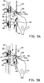
- the muscular stomach 81 will be situated on its back, at the side of the V rod 45 facing away from the carcass, as illustrated in figure 5F (see below).
- the wall 57a extends over the rod 45. This is so because in case the muscular stomach 81 is situated between the legs, and therefore remains out of reach of the rod 45, a stop for the muscular stomach is offered nonetheless, see figure 5F , No. 81'. The location of the muscular stomach depends on the eviscerator used.
- the entrails are transported away in the direction C with the conveyor belt 31, and at the end are discharged in the direction D to a discharge tray 90.
- the carcasses hanging from the brackets 13 continue their way in path 10e, in the direction E, for further processing.
- the belt conveyor 30 may for instance follow a path deviating from the overhead conveyor 10.
- the lower unit 28 has been provided with a movable bottom valve 49 which is suspended so as to hinge at the location of 90.
- a torsion spring 97 biasses the valve 49 to a closed position against the plate 44.
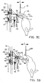
- an operating mechanism has been provided, built up from a rod with hinge ends 91 which at the location of 92 is hinged to the valve 49 and at the location of 93 to a lever 94, which at the location of 95 is hinged to lower unit 28 and to support member 41 and at the end has been provided with a roller 96, that is moved by a curve track (not shown) on the drum 22.
- the upper unit 29 has been supplemented with a further support member 110 having a control roller 115 that runs in a curve track (not shown) on the drum 22.
- a rod with hinge ends 111 has been hinged to the support member 110, which rod with hinge ends at the lower end at the location of 113 is hinged to the plate 57 that has been provided with a stop edge 57a.
- the plate 57 is hinged to the plate 53 at the location of 114. Because of the suitable course of the curve tracks for the rollers 52 and 115 the mutual distance between the support members 51 and 110 can be changed (direction M), as a result of which the plate 57 rotates in directions N, about hinge 114.
- the edge 57a after lowering the upper unit 29 - or in the end stage thereof -, is able to make a motion engaging rearward with respect to a muscular stomach that is situated between the legs, so that a proper engagement of the muscular stomach is ensured.
- the plate 57 is extended by rod 117, which at the location of 114 is hinged to lip 116 that is fixedly attached to the front side of plate 56, and at the location of 113 is hinged to rod with hinge ends 111.
- the rod 117 When slide or support member 110 is moved downward (M) the rod 117 will rotate from the position shown in dashed lines to the position shown in continuous lines. In that case the plate 57 will tilt in direction R towards the plate 56, as a result of which a muscular stomach optionally situated - as considered in the drawing - on the left of the plate 57 is slid to the plate 56.
- This can also be done prior to the lower unit 28 having been moved entirely upward, in order to position the muscular stomach such, that it will come to lie - as considered in the drawing- on the left hand side of the rod 45, within the walls 43a and plate 44.
Landscapes
- Life Sciences & Earth Sciences (AREA)
- Engineering & Computer Science (AREA)
- Wood Science & Technology (AREA)
- Zoology (AREA)
- Food Science & Technology (AREA)
- Control And Other Processes For Unpacking Of Materials (AREA)
- Processing Of Meat And Fish (AREA)
- Electrical Discharge Machining, Electrochemical Machining, And Combined Machining (AREA)
- Grinding-Machine Dressing And Accessory Apparatuses (AREA)
- Refuse Collection And Transfer (AREA)
- Chain Conveyers (AREA)
Claims (29)
- Vorrichtung (1) zum Trennen von Schlachtkörpern (K) kleiner Tiere von den Gebinden (80) mit aus den Schlachtkörpern entnommenen und damit durch die Speiseröhre (S) verbundenen Innereien, umfassend ein erstes Fördersystem (10), welches mit entsprechenden Haltern (13) für die Schlachtkörper für den Transport in Reihe der Schlachtkörper entlang einer ersten Bahn versehen ist, und ein zweites Fördersystem (20), welches mit einer Reihe von Abschirmungen/Rückhaltern (28, 29) zum Abschirmen/Rückhalten der Gebinde von den von den Haltern gehaltenen Schlachtkörpern versehen ist, wobei das zweite Fördersystem (20) für eine Bewegung entlang einer zweiten Bahn positioniert ist, wobei eine erste Spur (10b) zusammen mit dem ersten Fördersystem aufwärts führt, wobei die Gebinde (80) von den Abschirmungen/Rückhaltern (28, 29) eingegriffen werden können, und wobei eine nachfolgende zweite Spur (10c) von der ersten Bahn wegführt, um den Abstand zwischen den Schlachtkörpern (K) und den zugehörigen Gebinden (80) zu vergrößern, um die Speiseröhre (S) abzulösen oder durchzureißen, wobei die Abschirmungen/Rückhalter (28, 29) dafür ausgelegt sind, die gelösten Gebinde (80) auszustoßen.
- Vorrichtung (1) nach Anspruch 1, wobei die Abschirmungen/Rückhalter (28, 29) derart ausgebildet sind, dass die durch die Abschirmungen/Rückhalter (28, 29) auf die Gebinde (80) ausgeübte Abschirmungs-/Rückhaltekraft zu einer Abweichungsrichtung der zweiten Spur (10c) und der ersten Bahn entgegengesetzt ist.
- Vorrichtung (1) nach Anspruch 2, wobei die Abschirmungen/Rückhalter (28, 29) mit einem Element (45, 56) zum Eingreifen an den Gebinden (80) versehen sind, wobei das Element quer zu der Abweichungsrichtung positioniert ist.
- Vorrichtung (1) nach Anaspruch 1, 2 oder 3, wobei die Abschirmungen/Rückhalter (28, 29) nach oben und unten bewegt werden können, um in einer Abwärtsbewegung zwischen den Innereien (80) und dem Schlachtkörper (K) einzudringen.
- Vorrichtung nach einem der vorangehenden Ansprüche, welche ferner mit Eingreifmitteln (45, 56) zum Eingreifen über der Speiseröhre (S) an gegenüberliegenden Seiten versehen ist, um einen Rückhalter oder Anschlag für ein mit der Speiseröhre (S) verbundenes Innereiteil (80, 81) zu bilden, wobei sich der Rückhalter oder Anschlag mit der zweiten Bahn zusammen bewegt.
- Vorrichtung (1) nach Anspruch 5, wobei die Eingreifmittel (45, 46) Ränder umfassen, welche an einer Seite auf der Abschirmung/dem Rückhalter (28) und an der anderen Seite auf einem Anschlagelement (29) vorgesehen sind, welches sich entlang der zweiten Bahn bewegt, wobei die Abschirmung/der Rückhalter (28) und das Anschlagelement (29) bezüglich einander zwischen Positionen bewegbar sind, die relativ weit voneinander entfernt sind, und Positionen, die miteinander einen Anschlag bilden.
- Vorrichtung (1) nach einem der vorangehenden Ansprüche, wobei die Abschirmungen/Rückhalter (28, 29) jeweils einen Halter mit einem im Wesentlichen vertikalen Durchlass bilden.
- Vorrichtung (1) nach Anspruch 7, wobei die Abschirmungen/Rückhalter (28, 29) mit einer beweglichen Bodenwand (49) versehen sind, die zwischen einer Gebindehalteposition und einer Gebindedurchlassposition bewegbar ist.
- Vorrichtung (1) nach einem der vorangehenden Ansprüche, wobei die Abschirmungen/Rückhalter (28, 29) erste (28) und zweite (29) Abschirmungen/Rückhalter umfassen, die zueinander bewegbar sind, um eine Verengung (46) für einen Bestandteil der Gebinde in einer Betriebsposition gegenseitigen Zusammenwirkens zu bilden.
- Vorrichtung (1) nach Anspruch 9, wobei die ersten Abschirmungen/Rückhalter (28) bezüglich der Betriebsposition nach oben und die zweiten Abschirmungen/Rückhalter (29) nach unten bewegt werden können.
- Vorrichtung (1) nach Anspruch 9 oder 10, wobei sich die zweiten Abschirmungen/Rückhalter ( 29) mit einer Anschlagskante (56a) nach oben zu den ersten Abschirmungen/Rückhaltern (28), insbesondere einer Anschlagskante daran, erstrecken, wobei sie die Verengung (46) offen lassen.
- Vorrichtung (1) nach Anspruch 9,10 oder 11, wobei sich die zweiten Abschirmungen/Rückhalter (29) mit einer Anschlagskante (57a, 157a) über den ersten Abschirmungen/Rückhaltern (28), insbesondere über einer Anschlagskante (45) daran, erstrecken.
- Vorrichtung (1) nach Anspruch 12, wobei die Anschlagskante (157a) der zweiten Abschirmungen/Rückhalter (29), die sich über den ersten Abschirmungen/Rückhaltern (28) erstreckt, für eine Dreh- oder Schwingbewegung (R) von oben in Richtung der ersten Abschirmungen/Rückhalter (28) positioniert ist.
- Vorrichtung (1) nach Anspruch 12, wobei die Anschlagskante (157a) der zweiten Abschirmungen/Rückhalter die sich über den ersten Abschirmungen/Rückhaltern (28) erstreckt, für eine im Wesentlichen horizontale Dreh- oder Schwingbewegung (R) in Richtung der ersten Abschirmungen/Rückhalter (28) positioniert ist.
- Vorrichtung (1) nach einem der vorangehenden Ansprüche, welche ferner mit einem dritten Fördermittel (30) für den Transport (C) abgetrennter Gebinde (80) versehen ist, wobei die Abschirmungen/Rückhalter (28, 29) dafür ausgelegt sind, die Gebinde während der Bewegung entlang der zweiten Spur zu dem dritten Fördersystem auszustoßen.
- Vorrichtung (1) nach Anspruch 15, wobei das dritte Fördersystem unter wenigstens einem Teil der zweiten Spur und unter einer Abstoßspur des ersten Fördersystems stromabwärts des Beginns der zweiten Spur (10c) angeordnet ist.
- Vorrichtung (1) nach Anspruch 16, wobei der Beginn der zweiten Spur (10c) und der Beginn der Ausstoßspur des ersten Fördersystems (10) einen Abstand aufweisen.
- Vorrichtung (1) nach einem der vorangehenden Ansprüche, wobei das erste Fördersystem (10) ein Hängefördersystem (10) ist.
- Vorrichtung (1) nach einem der vorangehenden Ansprüche, wobei das zweite Fördersystem (20) ein Karussell (102, 103, 33) ist, an welchem die Abschirmungen/Rückhalter (28, 29) angeordnet sind.
- Vorrichtung (1) nach einem der vorangehenden Ansprüche, wobei die zweite Bahn über einer oder mehreren vertikalen Mittellinien zirkuliert, vorzugsweise gemäß einer kreisförmigen Bahn.
- Vorrichtung (1) nach einem der vorangehenden Ansprüche, wobei das dritte Fördersystem (30) ein Förderband (31) ist.
- Verfahren zum Trennen von Schlachtkörpern (k) kleiner Tiere von den Gebinden (80) mit aus den Schlachtkörpern entnommenen und damit durch die Speiseröhre (S) verbundenen Innereien, wobei die Schlachtkörper in Reihe entlang einer ersten Bahn transportiert werden, wobei sich mitbewegende Abschirmungen/Rückhalter zwischen den Schlachtkörpern (K) und den zugehörigen Gebinden (80) bewegt werden, wonach die Gebinde entlang einer zweiten Bahn, gefolgt von den Abschirmungen/Rückhaltern (28, 29) und abweichend (10c) von der ersten Bahn, gefolgt von den Schlachtkörpern, entlang der ersten Bahn von den Schlachtkörpern weggelenkt werden, um die Speiseröhre (S) abzulösen oder durchzureißen, wonach die Gebinde (80) zum Ausstoßen gesammelt werden.
- Verfahren nach Anspruch 22, wobei die Abschirmungen/Rückhalter (28, 29) eine Kraft auf die Gebinde (80) ausüben, die entgegengesetzt zu der Weglenkrichtung der ersten und zweiten Bahn ist.
- Verfahren nach Anspruch 22 oder 23, wobei die Abschirmungen/Rückhalter (28) in einer Aufwärtsrichtung zwischen Schlachtkörper (K) und Innereiengebinde (80) bewegt werden.
- Verfahren nach einem der Ansprüche 22-24, wobei die Abschirmungen/Rückhalter (28, 29) eine erste Kante aufweisen, welche in Zusammenwirken mit einer zweiten Kante (56a) entlang der zweiten Bahn eine Verengung (46) zum Anhalten des Innereiengebindes in einer Bewegung zu dem Schlachtkörper hin bildet, wobei die Speiseröhre (S) hindurchgelassen wird.
- Verfahren nach einem der Ansprüche 22-25, wobei die Speiseröhre (S) in der Nähe des Kaumagens durchgerissen wird.
- Verfahren nach einem der Ansprüche 22-26, wobei die Speiseröhre durch eine Trennung zwischen dem Muskelmagen (81) und dem Kaumagen durchgerissen wird.
- Verfahren nach einem der Ansprüche 22-27, wobei die Gebinde (80) nach dem Reißen der Speiseröhre (S) auf einen Auslass nach unten fallen.
- Verfahren nach einem der Ansprüche 22-28, wobei die Gebinde (80) auf einem Ausstoßförderband (30) gesammelt werden.
Applications Claiming Priority (1)
| Application Number | Priority Date | Filing Date | Title |
|---|---|---|---|
| NL1031380A NL1031380C2 (nl) | 2006-03-16 | 2006-03-16 | Afnemer van ingewandenpakketten. |
Publications (3)
| Publication Number | Publication Date |
|---|---|
| EP1834526A2 EP1834526A2 (de) | 2007-09-19 |
| EP1834526A3 EP1834526A3 (de) | 2008-04-23 |
| EP1834526B1 true EP1834526B1 (de) | 2009-12-16 |
Family
ID=37110226
Family Applications (1)
| Application Number | Title | Priority Date | Filing Date |
|---|---|---|---|
| EP07075198A Not-in-force EP1834526B1 (de) | 2006-03-16 | 2007-03-15 | Vorrichtung zum Aufnehmen von Innereien |
Country Status (5)
| Country | Link |
|---|---|
| EP (1) | EP1834526B1 (de) |
| AT (1) | ATE451839T1 (de) |
| DE (1) | DE602007003761D1 (de) |
| DK (1) | DK1834526T3 (de) |
| NL (1) | NL1031380C2 (de) |
Family Cites Families (3)
| Publication number | Priority date | Publication date | Assignee | Title |
|---|---|---|---|---|
| BE813138A (en) | 1974-04-01 | 1974-07-31 | Automatic removal of intestines from chickens - as part of an automatic line for preparing 'oven ready' chickens | |
| US4467498A (en) | 1983-11-21 | 1984-08-28 | Cantrell Machine Co., Inc. | Rotary viscera harvester |
| NL1017100C2 (nl) * | 2001-01-12 | 2002-07-22 | Stork Pmt | Werkwijze en inrichting voor het verwerken van een ingewandenpakket van een slachtdier. |
-
2006
- 2006-03-16 NL NL1031380A patent/NL1031380C2/nl not_active IP Right Cessation
-
2007
- 2007-03-15 EP EP07075198A patent/EP1834526B1/de not_active Not-in-force
- 2007-03-15 DK DK07075198.7T patent/DK1834526T3/da active
- 2007-03-15 AT AT07075198T patent/ATE451839T1/de not_active IP Right Cessation
- 2007-03-15 DE DE602007003761T patent/DE602007003761D1/de active Active
Also Published As
| Publication number | Publication date |
|---|---|
| EP1834526A2 (de) | 2007-09-19 |
| DK1834526T3 (da) | 2010-04-26 |
| DE602007003761D1 (de) | 2010-01-28 |
| ATE451839T1 (de) | 2010-01-15 |
| NL1031380C2 (nl) | 2007-09-18 |
| EP1834526A3 (de) | 2008-04-23 |
Similar Documents
| Publication | Publication Date | Title |
|---|---|---|
| DK2996481T3 (en) | PROCEDURE, SYSTEM AND LEADING DEVICE FOR SEPARATION OF INGESTION KITS SELECTED FROM Slaughtered Poultry | |
| US7597615B2 (en) | Method and device for processing a slaughter animal | |
| NL9300815A (nl) | Werkwijze en inrichting voor het verwijderen en verwerken van een organenpakket van een slachtdier. | |
| JPS6087728A (ja) | 自動充填装置において製造した個個のソ−セ−ジを薫煙・湯煮棒に並べる方法並びに装置 | |
| EP1222858B2 (de) | Verfahren und Vorrichtung zur Bearbeitung des Organ-Pakets eines Schlachttieres | |
| US20170318826A1 (en) | Direct hanging line | |
| DK3068230T3 (en) | Guide element, guide device, system and method for separating an entrails set taken from slaughtered poultry. | |
| JP6611783B2 (ja) | ソーセージ竿掛装置 | |
| NL9100153A (nl) | Inrichting voor het uithalen van slachtvogels. | |
| US20100003909A1 (en) | Puller for use in animal carcass boning or cutting | |
| EP1834526B1 (de) | Vorrichtung zum Aufnehmen von Innereien | |
| EP3962277B1 (de) | Hängeförderbahnsystem und -verfahren | |
| DK166858B1 (da) | Fremgangsmaade og anlaeg til afskinding af dyreskrog | |
| US9820495B2 (en) | Evisceration apparatus and a method for eviscerating suspended poultry | |
| EP1677611B1 (de) | Verfahren zum ausweiden von geschlachtetem geflügel, schlachtsystem zur behandlung der eingeweide von geschlachtetem geflügel und eingeweidehalter für eine eingeweidebeförderungseinrichtung in einem schlachtsystem | |
| US3835502A (en) | Hide pulling machine | |
| US7059953B2 (en) | Apparatus and a method for automatic cutting of organs from a plucks set from a carcass | |
| US10258053B2 (en) | Evisceration apparatus and a method for eviscerating suspended poultry | |
| EP1027829A1 (de) | Verfahren und Vorrichtung zum Lösen des Mastdarmes eines Schlachttierkörpers, und Vorrichtung zum Entnehmen des Anus | |
| US3656206A (en) | Article-release shackle for trolley-supported handling systems to facilitate processing | |
| EP0917824A2 (de) | Vorrichtung und Verfahren zum Schneiden der Luftröhre und der Speiseröhre eines Schlachttierkörpers |
Legal Events
| Date | Code | Title | Description |
|---|---|---|---|
| PUAI | Public reference made under article 153(3) epc to a published international application that has entered the european phase |
Free format text: ORIGINAL CODE: 0009012 |
|
| AK | Designated contracting states |
Kind code of ref document: A2 Designated state(s): AT BE BG CH CY CZ DE DK EE ES FI FR GB GR HU IE IS IT LI LT LU LV MC MT NL PL PT RO SE SI SK TR |
|
| AX | Request for extension of the european patent |
Extension state: AL BA HR MK YU |
|
| 17P | Request for examination filed |
Effective date: 20080108 |
|
| PUAL | Search report despatched |
Free format text: ORIGINAL CODE: 0009013 |
|
| AK | Designated contracting states |
Kind code of ref document: A3 Designated state(s): AT BE BG CH CY CZ DE DK EE ES FI FR GB GR HU IE IS IT LI LT LU LV MC MT NL PL PT RO SE SI SK TR |
|
| AX | Request for extension of the european patent |
Extension state: AL BA HR MK RS |
|
| 17Q | First examination report despatched |
Effective date: 20081017 |
|
| AKX | Designation fees paid |
Designated state(s): AT BE BG CH CY CZ DE DK EE ES FI FR GB GR HU IE IS IT LI LT LU LV MC MT NL PL PT RO SE SI SK TR |
|
| GRAP | Despatch of communication of intention to grant a patent |
Free format text: ORIGINAL CODE: EPIDOSNIGR1 |
|
| GRAS | Grant fee paid |
Free format text: ORIGINAL CODE: EPIDOSNIGR3 |
|
| GRAA | (expected) grant |
Free format text: ORIGINAL CODE: 0009210 |
|
| AK | Designated contracting states |
Kind code of ref document: B1 Designated state(s): AT BE BG CH CY CZ DE DK EE ES FI FR GB GR HU IE IS IT LI LT LU LV MC MT NL PL PT RO SE SI SK TR |
|
| REG | Reference to a national code |
Ref country code: GB Ref legal event code: FG4D |
|
| REG | Reference to a national code |
Ref country code: CH Ref legal event code: EP |
|
| REG | Reference to a national code |
Ref country code: IE Ref legal event code: FG4D |
|
| REF | Corresponds to: |
Ref document number: 602007003761 Country of ref document: DE Date of ref document: 20100128 Kind code of ref document: P |
|
| REG | Reference to a national code |
Ref country code: NL Ref legal event code: T3 |
|
| REG | Reference to a national code |
Ref country code: DK Ref legal event code: T3 |
|
| REG | Reference to a national code |
Ref country code: NL Ref legal event code: SD Effective date: 20100330 |
|
| PG25 | Lapsed in a contracting state [announced via postgrant information from national office to epo] |
Ref country code: SE Free format text: LAPSE BECAUSE OF FAILURE TO SUBMIT A TRANSLATION OF THE DESCRIPTION OR TO PAY THE FEE WITHIN THE PRESCRIBED TIME-LIMIT Effective date: 20091216 Ref country code: LT Free format text: LAPSE BECAUSE OF FAILURE TO SUBMIT A TRANSLATION OF THE DESCRIPTION OR TO PAY THE FEE WITHIN THE PRESCRIBED TIME-LIMIT Effective date: 20091216 Ref country code: FI Free format text: LAPSE BECAUSE OF FAILURE TO SUBMIT A TRANSLATION OF THE DESCRIPTION OR TO PAY THE FEE WITHIN THE PRESCRIBED TIME-LIMIT Effective date: 20091216 |
|
| LTIE | Lt: invalidation of european patent or patent extension |
Effective date: 20091216 |
|
| PG25 | Lapsed in a contracting state [announced via postgrant information from national office to epo] |
Ref country code: PL Free format text: LAPSE BECAUSE OF FAILURE TO SUBMIT A TRANSLATION OF THE DESCRIPTION OR TO PAY THE FEE WITHIN THE PRESCRIBED TIME-LIMIT Effective date: 20091216 Ref country code: LV Free format text: LAPSE BECAUSE OF FAILURE TO SUBMIT A TRANSLATION OF THE DESCRIPTION OR TO PAY THE FEE WITHIN THE PRESCRIBED TIME-LIMIT Effective date: 20091216 Ref country code: SI Free format text: LAPSE BECAUSE OF FAILURE TO SUBMIT A TRANSLATION OF THE DESCRIPTION OR TO PAY THE FEE WITHIN THE PRESCRIBED TIME-LIMIT Effective date: 20091216 |
|
| PG25 | Lapsed in a contracting state [announced via postgrant information from national office to epo] |
Ref country code: AT Free format text: LAPSE BECAUSE OF FAILURE TO SUBMIT A TRANSLATION OF THE DESCRIPTION OR TO PAY THE FEE WITHIN THE PRESCRIBED TIME-LIMIT Effective date: 20091216 |
|
| PG25 | Lapsed in a contracting state [announced via postgrant information from national office to epo] |
Ref country code: PT Free format text: LAPSE BECAUSE OF FAILURE TO SUBMIT A TRANSLATION OF THE DESCRIPTION OR TO PAY THE FEE WITHIN THE PRESCRIBED TIME-LIMIT Effective date: 20100416 Ref country code: IS Free format text: LAPSE BECAUSE OF FAILURE TO SUBMIT A TRANSLATION OF THE DESCRIPTION OR TO PAY THE FEE WITHIN THE PRESCRIBED TIME-LIMIT Effective date: 20100416 Ref country code: BG Free format text: LAPSE BECAUSE OF FAILURE TO SUBMIT A TRANSLATION OF THE DESCRIPTION OR TO PAY THE FEE WITHIN THE PRESCRIBED TIME-LIMIT Effective date: 20100316 Ref country code: EE Free format text: LAPSE BECAUSE OF FAILURE TO SUBMIT A TRANSLATION OF THE DESCRIPTION OR TO PAY THE FEE WITHIN THE PRESCRIBED TIME-LIMIT Effective date: 20091216 Ref country code: ES Free format text: LAPSE BECAUSE OF FAILURE TO SUBMIT A TRANSLATION OF THE DESCRIPTION OR TO PAY THE FEE WITHIN THE PRESCRIBED TIME-LIMIT Effective date: 20100327 Ref country code: RO Free format text: LAPSE BECAUSE OF FAILURE TO SUBMIT A TRANSLATION OF THE DESCRIPTION OR TO PAY THE FEE WITHIN THE PRESCRIBED TIME-LIMIT Effective date: 20091216 |
|
| PG25 | Lapsed in a contracting state [announced via postgrant information from national office to epo] |
Ref country code: CZ Free format text: LAPSE BECAUSE OF FAILURE TO SUBMIT A TRANSLATION OF THE DESCRIPTION OR TO PAY THE FEE WITHIN THE PRESCRIBED TIME-LIMIT Effective date: 20091216 Ref country code: BE Free format text: LAPSE BECAUSE OF FAILURE TO SUBMIT A TRANSLATION OF THE DESCRIPTION OR TO PAY THE FEE WITHIN THE PRESCRIBED TIME-LIMIT Effective date: 20091216 Ref country code: SK Free format text: LAPSE BECAUSE OF FAILURE TO SUBMIT A TRANSLATION OF THE DESCRIPTION OR TO PAY THE FEE WITHIN THE PRESCRIBED TIME-LIMIT Effective date: 20091216 |
|
| PLBI | Opposition filed |
Free format text: ORIGINAL CODE: 0009260 |
|
| 26 | Opposition filed |
Opponent name: MAREL STORK POULTRY PROCESSING B.V. Effective date: 20100915 |
|
| PG25 | Lapsed in a contracting state [announced via postgrant information from national office to epo] |
Ref country code: CY Free format text: LAPSE BECAUSE OF FAILURE TO SUBMIT A TRANSLATION OF THE DESCRIPTION OR TO PAY THE FEE WITHIN THE PRESCRIBED TIME-LIMIT Effective date: 20091216 Ref country code: MC Free format text: LAPSE BECAUSE OF NON-PAYMENT OF DUE FEES Effective date: 20100331 Ref country code: GR Free format text: LAPSE BECAUSE OF FAILURE TO SUBMIT A TRANSLATION OF THE DESCRIPTION OR TO PAY THE FEE WITHIN THE PRESCRIBED TIME-LIMIT Effective date: 20100317 |
|
| PLAX | Notice of opposition and request to file observation + time limit sent |
Free format text: ORIGINAL CODE: EPIDOSNOBS2 |
|
| PG25 | Lapsed in a contracting state [announced via postgrant information from national office to epo] |
Ref country code: IE Free format text: LAPSE BECAUSE OF NON-PAYMENT OF DUE FEES Effective date: 20100315 |
|
| PLAF | Information modified related to communication of a notice of opposition and request to file observations + time limit |
Free format text: ORIGINAL CODE: EPIDOSCOBS2 |
|
| PG25 | Lapsed in a contracting state [announced via postgrant information from national office to epo] |
Ref country code: IT Free format text: LAPSE BECAUSE OF FAILURE TO SUBMIT A TRANSLATION OF THE DESCRIPTION OR TO PAY THE FEE WITHIN THE PRESCRIBED TIME-LIMIT Effective date: 20091216 |
|
| RAP2 | Party data changed (patent owner data changed or rights of a patent transferred) |
Owner name: NUMAFA HOLDING B.V. |
|
| PG25 | Lapsed in a contracting state [announced via postgrant information from national office to epo] |
Ref country code: MT Free format text: LAPSE BECAUSE OF FAILURE TO SUBMIT A TRANSLATION OF THE DESCRIPTION OR TO PAY THE FEE WITHIN THE PRESCRIBED TIME-LIMIT Effective date: 20091216 |
|
| PLBB | Reply of patent proprietor to notice(s) of opposition received |
Free format text: ORIGINAL CODE: EPIDOSNOBS3 |
|
| REG | Reference to a national code |
Ref country code: CH Ref legal event code: PL |
|
| PG25 | Lapsed in a contracting state [announced via postgrant information from national office to epo] |
Ref country code: LI Free format text: LAPSE BECAUSE OF NON-PAYMENT OF DUE FEES Effective date: 20110331 Ref country code: CH Free format text: LAPSE BECAUSE OF NON-PAYMENT OF DUE FEES Effective date: 20110331 |
|
| PLCK | Communication despatched that opposition was rejected |
Free format text: ORIGINAL CODE: EPIDOSNREJ1 |
|
| APBM | Appeal reference recorded |
Free format text: ORIGINAL CODE: EPIDOSNREFNO |
|
| APBP | Date of receipt of notice of appeal recorded |
Free format text: ORIGINAL CODE: EPIDOSNNOA2O |
|
| APAH | Appeal reference modified |
Free format text: ORIGINAL CODE: EPIDOSCREFNO |
|
| APBQ | Date of receipt of statement of grounds of appeal recorded |
Free format text: ORIGINAL CODE: EPIDOSNNOA3O |
|
| PG25 | Lapsed in a contracting state [announced via postgrant information from national office to epo] |
Ref country code: HU Free format text: LAPSE BECAUSE OF FAILURE TO SUBMIT A TRANSLATION OF THE DESCRIPTION OR TO PAY THE FEE WITHIN THE PRESCRIBED TIME-LIMIT Effective date: 20100617 Ref country code: LU Free format text: LAPSE BECAUSE OF NON-PAYMENT OF DUE FEES Effective date: 20100315 |
|
| PG25 | Lapsed in a contracting state [announced via postgrant information from national office to epo] |
Ref country code: TR Free format text: LAPSE BECAUSE OF FAILURE TO SUBMIT A TRANSLATION OF THE DESCRIPTION OR TO PAY THE FEE WITHIN THE PRESCRIBED TIME-LIMIT Effective date: 20091216 |
|
| PLAB | Opposition data, opponent's data or that of the opponent's representative modified |
Free format text: ORIGINAL CODE: 0009299OPPO |
|
| R26 | Opposition filed (corrected) |
Opponent name: MAREL STORK POULTRY PROCESSING B.V. Effective date: 20100915 |
|
| REG | Reference to a national code |
Ref country code: FR Ref legal event code: PLFP Year of fee payment: 10 |
|
| PGFP | Annual fee paid to national office [announced via postgrant information from national office to epo] |
Ref country code: DE Payment date: 20160219 Year of fee payment: 10 Ref country code: NL Payment date: 20160304 Year of fee payment: 10 Ref country code: DK Payment date: 20160302 Year of fee payment: 10 |
|
| PGFP | Annual fee paid to national office [announced via postgrant information from national office to epo] |
Ref country code: GB Payment date: 20160205 Year of fee payment: 10 Ref country code: FR Payment date: 20160316 Year of fee payment: 10 |
|
| REG | Reference to a national code |
Ref country code: DE Ref legal event code: R100 Ref document number: 602007003761 Country of ref document: DE |
|
| APBU | Appeal procedure closed |
Free format text: ORIGINAL CODE: EPIDOSNNOA9O |
|
| PLBN | Opposition rejected |
Free format text: ORIGINAL CODE: 0009273 |
|
| STAA | Information on the status of an ep patent application or granted ep patent |
Free format text: STATUS: OPPOSITION REJECTED |
|
| 27O | Opposition rejected |
Effective date: 20161013 |
|
| REG | Reference to a national code |
Ref country code: DE Ref legal event code: R119 Ref document number: 602007003761 Country of ref document: DE |
|
| REG | Reference to a national code |
Ref country code: DK Ref legal event code: EBP Effective date: 20170331 |
|
| REG | Reference to a national code |
Ref country code: NL Ref legal event code: MM Effective date: 20170401 |
|
| GBPC | Gb: european patent ceased through non-payment of renewal fee |
Effective date: 20170315 |
|
| REG | Reference to a national code |
Ref country code: FR Ref legal event code: ST Effective date: 20171130 |
|
| PG25 | Lapsed in a contracting state [announced via postgrant information from national office to epo] |
Ref country code: FR Free format text: LAPSE BECAUSE OF NON-PAYMENT OF DUE FEES Effective date: 20170331 Ref country code: NL Free format text: LAPSE BECAUSE OF NON-PAYMENT OF DUE FEES Effective date: 20170401 Ref country code: DE Free format text: LAPSE BECAUSE OF NON-PAYMENT OF DUE FEES Effective date: 20171003 |
|
| PG25 | Lapsed in a contracting state [announced via postgrant information from national office to epo] |
Ref country code: GB Free format text: LAPSE BECAUSE OF NON-PAYMENT OF DUE FEES Effective date: 20170315 |
|
| PG25 | Lapsed in a contracting state [announced via postgrant information from national office to epo] |
Ref country code: DK Free format text: LAPSE BECAUSE OF NON-PAYMENT OF DUE FEES Effective date: 20170331 |