EP1834557B1 - Cuve d'un barbecue électrique - Google Patents
Cuve d'un barbecue électrique Download PDFInfo
- Publication number
- EP1834557B1 EP1834557B1 EP20070290315 EP07290315A EP1834557B1 EP 1834557 B1 EP1834557 B1 EP 1834557B1 EP 20070290315 EP20070290315 EP 20070290315 EP 07290315 A EP07290315 A EP 07290315A EP 1834557 B1 EP1834557 B1 EP 1834557B1
- Authority
- EP
- European Patent Office
- Prior art keywords
- pan
- tank
- barbecue
- stick coating
- water
- Prior art date
- Legal status (The legal status is an assumption and is not a legal conclusion. Google has not performed a legal analysis and makes no representation as to the accuracy of the status listed.)
- Not-in-force
Links
- 235000021168 barbecue Nutrition 0.000 title claims description 13
- XLYOFNOQVPJJNP-UHFFFAOYSA-N water Substances O XLYOFNOQVPJJNP-UHFFFAOYSA-N 0.000 claims description 14
- 239000011248 coating agent Substances 0.000 claims description 10
- 238000000576 coating method Methods 0.000 claims description 10
- 238000010411 cooking Methods 0.000 description 11
- 238000005485 electric heating Methods 0.000 description 5
- 235000013305 food Nutrition 0.000 description 5
- 235000011389 fruit/vegetable juice Nutrition 0.000 description 3
- 230000005855 radiation Effects 0.000 description 3
- 238000004140 cleaning Methods 0.000 description 2
- JEIPFZHSYJVQDO-UHFFFAOYSA-N iron(III) oxide Inorganic materials O=[Fe]O[Fe]=O JEIPFZHSYJVQDO-UHFFFAOYSA-N 0.000 description 1
- 239000007788 liquid Substances 0.000 description 1
- 239000000463 material Substances 0.000 description 1
- 239000002184 metal Substances 0.000 description 1
- 230000002093 peripheral effect Effects 0.000 description 1
- 238000002310 reflectometry Methods 0.000 description 1
Images
Classifications
-
- A—HUMAN NECESSITIES
- A47—FURNITURE; DOMESTIC ARTICLES OR APPLIANCES; COFFEE MILLS; SPICE MILLS; SUCTION CLEANERS IN GENERAL
- A47J—KITCHEN EQUIPMENT; COFFEE MILLS; SPICE MILLS; APPARATUS FOR MAKING BEVERAGES
- A47J37/00—Baking; Roasting; Grilling; Frying
- A47J37/06—Roasters; Grills; Sandwich grills
- A47J37/07—Roasting devices for outdoor use; Barbecues
- A47J37/0786—Accessories
-
- A—HUMAN NECESSITIES
- A47—FURNITURE; DOMESTIC ARTICLES OR APPLIANCES; COFFEE MILLS; SPICE MILLS; SUCTION CLEANERS IN GENERAL
- A47J—KITCHEN EQUIPMENT; COFFEE MILLS; SPICE MILLS; APPARATUS FOR MAKING BEVERAGES
- A47J37/00—Baking; Roasting; Grilling; Frying
- A47J37/06—Roasters; Grills; Sandwich grills
- A47J37/07—Roasting devices for outdoor use; Barbecues
- A47J37/0704—Roasting devices for outdoor use; Barbecues with horizontal fire box
- A47J37/0709—Roasting devices for outdoor use; Barbecues with horizontal fire box with electric heating elements
Definitions
- the present invention relates to a tank of an electric barbecue.
- an electric barbecue comprises a cooking surface adapted to support a food to be cooked, an electric heating device disposed in the cooking surface and adapted to cook the food, and a tank adapted to support the cooking surface and the electric heater and to contain water.
- Water is used, according barbecues, to thermally protect the walls of the tank when it is made of a material poorly withstanding the high temperatures, and / or to cool the cooking juices from the food and prevent that they burn in contact with a reception surface (generally metal) at high temperature carried either by the tank itself, or by a thermal reflector floating in the tank.
- EP Patent No. 1,057,437 A discloses an electrical apparatus with a non-stick coating inner shell.
- the problem is that it is often difficult to properly clean the tank (i.e. the water tank and / or the thermal reflector) of an electric barbecue.
- the present invention aims to provide an easily cleanable tank.
- the tank comprises on its outer and inner outer faces a non-stick coating.
- the presence of the non-stick coating makes it possible to very easily clean the tank, as well their internal face (presence of concentrated cooking juices in the case of a thermal reflector, presence of fatty water in the case of a water tank also acting as thermal reflector, presence of water having heated in the case of a water tank) that their outer face (presence of water having heated in the case of a thermal reflector, risk of run-off of the liquid contained in the water tank during its cleaning).
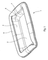
- the water tank 1 illustrated in figure 1 is part of a compact electric barbecue that includes a cooking surface adapted to support a food to be cooked, an electric heating device disposed in the cooking surface and adapted to cook the food, a tank 1 adapted to support the surface of cooking and the electric heater, and feet. Due to the compactness of the barbecue, the tank 1 is adapted, on the one hand, to contain water so as to thermally isolate the support on which the electric barbecue rests and to receive the cooking juices while preventing them from burn, and, secondly, to act as a thermal reflector so as to reflect towards the cooking surface the thermal radiation emitted by the electric heating device to the tank 1 and, consequently, to thermally isolate the support on which rests the electric barbecue.
- the tank 1 defines a volume which is delimited by a bottom wall 2 and side walls 3 (here, four side walls 3).
- the side walls 3 join the bottom wall 2 by substantially horizontal edges 4 and they meet two by two along substantially vertical edges 5.
- the free end of the side walls is extended by a peripheral flange 6 which extends outwardly of the vessel 1, substantially horizontally.
- the horizontal and vertical 5 ridges 4 are rounded.
- the vessel 1 comprises on its outer and inner outer faces a non-stick coating.
- the non-stick coating used can be the same for both sides of the tank 1.
- the use of the release coating protects the tank 1 from rust.
- the use of a coating giving a light gray appearance on the inner and outer faces of the tank 1 reduces the size of the barbecue, and more specifically, reduces the height of the feet that support the tank 1 (This is notable in the case of table barbecue).
- the light gray color apparent on the inner side allows for a high reflectivity.
- the majority of the thermal energy received by radiation from the electric heating device (of the electric heating resistance) is returned to the cooking surface and is very little absorbed by the tank 1.
- this same apparent light gray color on the outer face allows a low emissivity, which means that the small amount of energy absorbed by the tank 1 is only very fear re-emitted by thermal radiation (in the direction of the outside and therefore towards the support of the barbecue).
- the apparent color is Pantone 8001C or RAL 9006.
- the invention is not limited to the embodiment given by way of example. So the tank might not serve as a thermal reflector but contain water on which a thermal reflector would float. The invention could also be applied to a thermal reflector not acting as a water tank, but floating in a tank.
Landscapes
- Engineering & Computer Science (AREA)
- Food Science & Technology (AREA)
- Baking, Grill, Roasting (AREA)
Description
- La présente invention concerne une cuve d'un barbecue électrique.
- De façon classique, un barbecue électrique comprend une surface de cuisson adaptée à supporter un aliment à cuire, un dispositif électrique de chauffe disposé dans la surface de cuisson et adapté à cuire l'aliment, et une cuve adaptée à supporter la surface de cuisson et le dispositif électrique de chauffe et à contenir de l'eau. L'eau est utilisée, selon les barbecues, pour protéger thermiquement les parois de la cuve quand celle-ci est réalisée en une matière supportant mal les températures élevées, et/ou pour refroidir les jus de cuisson provenant de l'aliment et éviter qu'ils ne brûlent au contact d'une surface de réception (en général en métal) à température élevée portée soit par la cuve elle-même, soit par un réflecteur thermique flottant dans la cuve.
- La demande de
brevet EP 1 057 437 A décrit un appareil électrique avec une cuve de emisson à revêtement intérieur anti-adhésif. - Le problème est qu'il est souvent malaisé de nettoyer correctement la cuve (c'est-à-dire la cuve à eau et/ou le réflecteur thermique) d'un barbecue électrique.
- La présente invention vise à réaliser une cuve facilement nettoyable.
- Selon l'invention, la cuve comprend sur ses faces externes intérieure et extérieure un revêtement anti-adhésif.
- La présence du revêtement anti-adhésif permet de nettoyer très facilement la cuve, aussi bien leur face intérieur (présence de jus de cuisson concentrés dans le cas d'un réflecteur thermique, présence d'eau grasse dans le cas d'une cuve à eau faisant également office de réflecteur thermique, présence d'eau ayant chauffée dans le cas d'une cuve à eau) que leur face extérieure (présence d'eau ayant chauffée dans le cas d'un réflecteur thermique, risque de coulure du liquide contenu dans la cuve à eau lors de son nettoyage).
- D'autres particularités et avantages apparaîtront dans la description du mode de réalisation donné à titre d'exemple non limitatif et illustré au dessin représentant en perspective une cuve conforme à la présente invention.
- La cuve 1 à eau illustrée à la
figure 1 fait partie d'un barbecue électrique compact qui comprend une surface de cuisson adaptée à supporter un aliment à cuire, un dispositif électrique de chauffe disposé dans la surface de cuisson et adapté à cuire l'aliment, une cuve 1 adaptée à supporter la surface de cuisson et le dispositif électrique de chauffe, et des pieds. Du fait de la compacité du barbecue, la cuve 1 est adaptée, d'une part, à contenir de l'eau de façon à isoler thermiquement le support sur lequel repose le barbecue électrique et à recevoir les jus de cuisson tout en les empêchant de brûler, et, d'autre part, à faire office de réflecteur thermique de façon à réfléchir vers la surface de cuisson le rayonnement thermique émis par le dispositif électrique de chauffe vers la cuve 1 et, en conséquence, à isoler thermiquement le support sur lequel repose le barbecue électrique. - La cuve 1 définit un volume qui est délimité par une paroi de fond 2 et des parois latérales 3 (ici, quatre parois latérales 3). Les parois latérales 3 rejoignent la paroi de fond 2 par des arêtes 4 sensiblement horizontales et elles se rejoignent deux à deux selon des arêtes 5 sensiblement verticales. Par ailleurs, pour faciliter la manipulation de la cuve 1, l'extrémité libre des parois latérales est prolongée par un rebord périphérique 6 qui s'étend vers l'extérieur de la cuve 1, de façon sensiblement horizontale. Dans le présent mode de réalisation, afin de faciliter le nettoyage de la cuve 1, les arêtes horizontales 5 et verticales 4 sont arrondies.
- Selon l'invention, la cuve 1 comprend sur ses faces externes intérieure et extérieure un revêtement anti-adhésif.
- Le revêtement anti-adhésif utilisé peut être le même pour les deux faces de la cuve 1.
- De plus, l'utilisation du revêtement anti-adhésif permet de protéger la cuve 1 de la rouille.
- Par ailleurs, l'emploi d'un revêtement donnant une apparence gris clair sur les faces interne et externe de la cuve 1 permet de réduire l'encombrement du barbecue, et plus précisément, permet de réduire la hauteur des pieds qui supportent la cuve 1 (ce qui est notable dans le cas de barbecue de table). En effet, la couleur gris clair apparente sur la face intérieure permet d'avoir un fort pouvoir réfléchissant. De ce fait, la majorité de l'énergie thermique reçue par rayonnement provenant du dispositif électrique de chauffe (de la résistance électrique de chauffe) est renvoyée vers la surface de cuisson et est très peu absorbée par la cuve 1. De plus, cette même couleur gris clair apparente sur la face extérieure permet d'avoir un faible pouvoir émissif, ce qui signifie que la faible quantité d'énergie absorbée par la cuve 1 n'est que très peur re-émise par rayonnement thermique (en direction de l'extérieur et donc en direction du support du barbecue). De préférence, la couleur apparente a pour indice Pantone 8001C ou RAL 9006.
- L'invention n'est pas limitée au mode de réalisation donné à titre d'exemple. Ainsi, la cuve pourrait ne pas servir de réflecteur thermique mais contenir de l'eau sur laquelle un réflecteur thermique flotterait. L'invention pourrait aussi s'appliquer à un réflecteur thermique ne faisant pas office de cuve à eau, mais flottant dans une cuve.
Claims (9)
- Cuve (1) d'un barbecue électrique comprenant un revêtement anti-adhésif sur sa face intérieure, caractérisée en ce qu'elle comprend également un revêtement anti-adhésif sur sa face extérieure.
- Cuve (1) selon la revendication 1, caractérisée en ce que le revêtement anti-adhésif appliqué sur la face intérieure est le même que celui appliqué sur la face extérieure.
- Cuve (1) selon la revendication 1 ou 2, caractérisée en ce que sa couleur apparente sur ses faces intérieure et extérieure est gris clair.
- Cuve (1) selon la revendication 3, caractérisée en ce que sa couleur apparente de sa face intérieure est la même que celle de sa face extérieure.
- Cuve (1) selon la revendication 3 ou 4, caractérisée en ce que la couleur apparente a pour indice Pantone 8001C ou RAL 9006.
- Cuve (1) selon l'une des revendications 1 à 5, caractérisée en ce que chaque arête (5) reliant deux parois latérales (3) de la cuve (1) est arrondie.
- Cuve (1) selon l'une des revendications 1 à 6, caractérisée en ce que chaque arête (4) reliant une paroi latérale (3) à la paroi de fond (2) de la cuve (1) est arrondie.
- Cuve (1) selon l'une des revendications 1 à 7 formant cuve à eau.
- Cuve (1) selon l'une des revendications 1 à 7 formant réflecteur thermique.
Applications Claiming Priority (1)
| Application Number | Priority Date | Filing Date | Title |
|---|---|---|---|
| FR0602331A FR2898478B1 (fr) | 2006-03-16 | 2006-03-16 | Cuve d'un barbecue electrique |
Publications (2)
| Publication Number | Publication Date |
|---|---|
| EP1834557A1 EP1834557A1 (fr) | 2007-09-19 |
| EP1834557B1 true EP1834557B1 (fr) | 2012-04-11 |
Family
ID=37216170
Family Applications (1)
| Application Number | Title | Priority Date | Filing Date |
|---|---|---|---|
| EP20070290315 Not-in-force EP1834557B1 (fr) | 2006-03-16 | 2007-03-13 | Cuve d'un barbecue électrique |
Country Status (3)
| Country | Link |
|---|---|
| EP (1) | EP1834557B1 (fr) |
| CN (1) | CN101081146A (fr) |
| FR (1) | FR2898478B1 (fr) |
Family Cites Families (4)
| Publication number | Priority date | Publication date | Assignee | Title |
|---|---|---|---|---|
| FR2730796B1 (fr) * | 1995-02-16 | 1997-04-18 | Seb Sa | Appareil de cuisson muni d'un element chauffant mobile |
| FR2759842B1 (fr) * | 1997-02-14 | 1999-04-16 | Seb Sa | Appareil electrique de grillage ou de rechauffage d'aliment plan |
| FR2794014B1 (fr) * | 1999-05-31 | 2001-07-27 | Seb Sa | Appareil culinaire electrique multi-fonctions |
| JP2003276129A (ja) * | 2002-03-26 | 2003-09-30 | Osaka Gas Co Ltd | 遠赤外線効果を有するコーティング構造 |
-
2006
- 2006-03-16 FR FR0602331A patent/FR2898478B1/fr not_active Expired - Fee Related
-
2007
- 2007-03-13 EP EP20070290315 patent/EP1834557B1/fr not_active Not-in-force
- 2007-03-15 CN CNA2007100870457A patent/CN101081146A/zh active Pending
Also Published As
| Publication number | Publication date |
|---|---|
| FR2898478B1 (fr) | 2010-05-28 |
| FR2898478A1 (fr) | 2007-09-21 |
| EP1834557A1 (fr) | 2007-09-19 |
| CN101081146A (zh) | 2007-12-05 |
Similar Documents
| Publication | Publication Date | Title |
|---|---|---|
| CA2805606C (fr) | Appareil de cuisson en deux zones | |
| FR2794014A1 (fr) | Appareil culinaire electrique multi-fonctions | |
| WO1996004832A1 (fr) | Appareil de chauffe pour aliments, en particulier pour la realisation de fritures, comportant une contre-cuve | |
| US11992152B2 (en) | Rotisserie grill | |
| EP0818168A1 (fr) | Appareil de cuisson comportant une plaque et un récipient de cuisson | |
| FR2670274A1 (fr) | Appareil de cuisson electrique a reflecteur. | |
| CA1314400C (fr) | Combine de cuisson | |
| EP1834557B1 (fr) | Cuve d'un barbecue électrique | |
| WO1990011038A1 (fr) | Appareil de cuisson autonome d'aliments | |
| EP0811346B1 (fr) | Appareil de cuisson de table à utilisations multiples | |
| EP2401948B1 (fr) | Appareil de cuisson électrique avec cuve et réflecteur | |
| CN223275319U (zh) | 一种煎烤器 | |
| JP3193322U (ja) | 固体燃料用携帯型コンロ | |
| FR2916129A1 (fr) | Appareil de cuisson electrique du type barbecue | |
| FR2903291A1 (fr) | Dispositif pour le reglage en hauteur de la surface de cuisson d'un appareil de cuisson | |
| FR3063624B1 (fr) | Dispositif de cuisson en exterieur | |
| FR2898479A1 (fr) | Cuve d'un barbecue electrique | |
| FR2559369A2 (fr) | Appareil culinaire pour preparer des sandwichs du genre dits " hamburgers " | |
| JP2004141362A (ja) | ゆで容器 | |
| FR2671858A1 (fr) | Procede et module de cuisson anti-projection pour four de cuisiniere. | |
| EP0914792B1 (fr) | Combiné de service de table chauffant et isothermique | |
| FR2711499A1 (fr) | Appareil polyvalent pour cuire ou griller des aliments sur une pierre ou toute plaque de cuisson au choix. | |
| FR2979189A1 (fr) | Couvercle de machine a pain | |
| FR2577785A1 (fr) | Ustensile de cuisine multi-fonctions | |
| RU138644U1 (ru) | Электрический чайник |
Legal Events
| Date | Code | Title | Description |
|---|---|---|---|
| PUAI | Public reference made under article 153(3) epc to a published international application that has entered the european phase |
Free format text: ORIGINAL CODE: 0009012 |
|
| AK | Designated contracting states |
Kind code of ref document: A1 Designated state(s): AT BE BG CH CY CZ DE DK EE ES FI FR GB GR HU IE IS IT LI LT LU LV MC MT NL PL PT RO SE SI SK TR |
|
| AX | Request for extension of the european patent |
Extension state: AL BA HR MK YU |
|
| RIN1 | Information on inventor provided before grant (corrected) |
Inventor name: VIRET, FRANCK Inventor name: DAUVERGNE, FRANCOIS |
|
| 17P | Request for examination filed |
Effective date: 20080215 |
|
| 17Q | First examination report despatched |
Effective date: 20080318 |
|
| AKX | Designation fees paid |
Designated state(s): DE FR TR |
|
| REG | Reference to a national code |
Ref country code: DE Ref legal event code: R079 Ref document number: 602007021863 Country of ref document: DE Free format text: PREVIOUS MAIN CLASS: A47J0037060000 Ipc: A47J0037070000 |
|
| GRAP | Despatch of communication of intention to grant a patent |
Free format text: ORIGINAL CODE: EPIDOSNIGR1 |
|
| RIC1 | Information provided on ipc code assigned before grant |
Ipc: A47J 37/07 20060101AFI20111012BHEP |
|
| GRAS | Grant fee paid |
Free format text: ORIGINAL CODE: EPIDOSNIGR3 |
|
| GRAA | (expected) grant |
Free format text: ORIGINAL CODE: 0009210 |
|
| AK | Designated contracting states |
Kind code of ref document: B1 Designated state(s): DE FR TR |
|
| REG | Reference to a national code |
Ref country code: DE Ref legal event code: R096 Ref document number: 602007021863 Country of ref document: DE Effective date: 20120606 |
|
| PLBE | No opposition filed within time limit |
Free format text: ORIGINAL CODE: 0009261 |
|
| STAA | Information on the status of an ep patent application or granted ep patent |
Free format text: STATUS: NO OPPOSITION FILED WITHIN TIME LIMIT |
|
| 26N | No opposition filed |
Effective date: 20130114 |
|
| REG | Reference to a national code |
Ref country code: DE Ref legal event code: R097 Ref document number: 602007021863 Country of ref document: DE Effective date: 20130114 |
|
| REG | Reference to a national code |
Ref country code: DE Ref legal event code: R119 Ref document number: 602007021863 Country of ref document: DE Effective date: 20131001 |
|
| PG25 | Lapsed in a contracting state [announced via postgrant information from national office to epo] |
Ref country code: DE Free format text: LAPSE BECAUSE OF NON-PAYMENT OF DUE FEES Effective date: 20131001 |
|
| REG | Reference to a national code |
Ref country code: FR Ref legal event code: PLFP Year of fee payment: 9 |
|
| PGFP | Annual fee paid to national office [announced via postgrant information from national office to epo] |
Ref country code: TR Payment date: 20150304 Year of fee payment: 9 |
|
| PGFP | Annual fee paid to national office [announced via postgrant information from national office to epo] |
Ref country code: FR Payment date: 20150331 Year of fee payment: 9 |
|
| REG | Reference to a national code |
Ref country code: FR Ref legal event code: ST Effective date: 20161130 |
|
| PG25 | Lapsed in a contracting state [announced via postgrant information from national office to epo] |
Ref country code: FR Free format text: LAPSE BECAUSE OF NON-PAYMENT OF DUE FEES Effective date: 20160331 |
|
| PG25 | Lapsed in a contracting state [announced via postgrant information from national office to epo] |
Ref country code: TR Free format text: LAPSE BECAUSE OF NON-PAYMENT OF DUE FEES Effective date: 20160313 |