EP1834564A2 - Séchoir de serviette pour véhicule mobile de loisirs - Google Patents
Séchoir de serviette pour véhicule mobile de loisirs Download PDFInfo
- Publication number
- EP1834564A2 EP1834564A2 EP07005477A EP07005477A EP1834564A2 EP 1834564 A2 EP1834564 A2 EP 1834564A2 EP 07005477 A EP07005477 A EP 07005477A EP 07005477 A EP07005477 A EP 07005477A EP 1834564 A2 EP1834564 A2 EP 1834564A2
- Authority
- EP
- European Patent Office
- Prior art keywords
- hot air
- towel dryer
- suspension element
- air
- towel
- Prior art date
- Legal status (The legal status is an assumption and is not a legal conclusion. Google has not performed a legal analysis and makes no representation as to the accuracy of the status listed.)
- Withdrawn
Links
Images


Classifications
-
- A—HUMAN NECESSITIES
- A47—FURNITURE; DOMESTIC ARTICLES OR APPLIANCES; COFFEE MILLS; SPICE MILLS; SUCTION CLEANERS IN GENERAL
- A47K—SANITARY EQUIPMENT; ACCESSORIES THEREFOR, e.g. TOILET ACCESSORIES
- A47K10/00—Body-drying implements; Toilet paper; Holders therefor
- A47K10/04—Towel racks; Towel rails; Towel rods; Towel rolls, e.g. rotatable
- A47K10/06—Towel racks; Towel rails; Towel rods; Towel rolls, e.g. rotatable combined with means for drying towels
-
- F—MECHANICAL ENGINEERING; LIGHTING; HEATING; WEAPONS; BLASTING
- F28—HEAT EXCHANGE IN GENERAL
- F28D—HEAT-EXCHANGE APPARATUS, NOT PROVIDED FOR IN ANOTHER SUBCLASS, IN WHICH THE HEAT-EXCHANGE MEDIA DO NOT COME INTO DIRECT CONTACT
- F28D21/00—Heat-exchange apparatus not covered by any of the groups F28D1/00 - F28D20/00
- F28D2021/0019—Other heat exchangers for particular applications; Heat exchange systems not otherwise provided for
- F28D2021/0035—Other heat exchangers for particular applications; Heat exchange systems not otherwise provided for for domestic or space heating, e.g. heating radiators
- F28D2021/0036—Radiators for drying, e.g. towel radiators
Definitions
- the present invention relates to a towel dryer for a recreational vehicle, having at least one suspension element for suspending at least one textile product, preferably a towel, wherein the at least one suspension element preferably has a rectilinear longitudinal extent.
- the invention has for its object to provide a towel dryer for a recreational vehicle, with a fast drying of fabrics, especially towels, with low energy consumption is possible.
- the object is achieved by a towel dryer according to claim 1.
- a towel dryer for a recreational vehicle has at least one suspension element for suspending a textile product and is characterized in that the suspension element is designed so hollow that it can be flowed through by air, in particular hot air along its longitudinal extent.
- the suspension element has at least one opening for discharging the air to the environment.
- the drying of the textile product can be particularly effective with the help of hot air. Likewise, it is also possible to let out only unheated air from the environment via the suspension element to dry in this way towels or other textile products.
- a fabric especially a towel provided suspension element, which may be formed hollow for the flow of hot air.
- the removal of the hot air flowing through the suspension element can take place via at least one opening formed in the suspension element, which preferably has a substantially vertically downwards discharge or outflow of hot air into an external environment, such as the interior of a typical leisure vehicle (caravan, motorhome, etc .).
- a towel held on the hanging element can be very effectively dried by the outflowing heated air, which is typically taken from recreational vehicles a hot air distribution system of a liquefied gas heating.
- the heated air can flow, for example, between the two opposite sections of a towel suspended on the suspension element.
- the heated air flows immediately after outflow from the Abschlement past the fabric to be dried, whereby a very effective drying can be realized. This avoids that the heated air flows upwards as a result of its buoyancy without having previously flown past the textile product to be dried.
- the suspension element along its longitudinal extension, in particular along its entire longitudinal extension, a non-self-contained, z. B. constant cross-section.
- This inventive design of the Ab yogalements which is formed in a practical development in the form of a tubular element, a z. B. along the entire longitudinal extent the Ab yogalements extending opening can be removed by the hot air into the outside environment.
- the opening may be designed such that the flow velocity of the hot air is kept in the suspension element so high that over the entire outlet opening a uniform outflow of warm air can be realized. Thus, even drying of the textile products held on the suspension element can be realized.
- the cross section of the at least one hanging element is oval-shaped.
- An oval-shaped cross-section is statically advantageous and makes it possible to use besides textile products, e.g. Gloves and T-shirts, even heavier items, such as ski boots to push the suspension element, the suspension element may consist of a metallic material or plastic.
- suspension elements according to the invention are designed to be pushed twice or three times into one another so that they can be quickly and precisely mounted on site by means of a designated click system.
- the towel according to the invention comprises a tubular support member on which the at least one suspension element is mounted such that through the tubular support member incoming warm air flows through the at least one suspension element.
- the support member may be attached, for example, to an inner wall of a recreational vehicle, so as to fix the towel dryer according to the invention fixed.
- the warm air which can be taken in recreational vehicles typically a hot air distribution system of an electric, diesel or LPG heating, according to the invention can flow into the tubular support member and via a suitable connection between the flow path of the support member and the flow path of Ab torquelements makes flow into the suspension element, to dry textile products or, if appropriate, other articles held on the suspension element.
- the at least one suspension element is pivotally mounted on the support element, which conveniently several textiles can be kept on the towel dryer.
- the support member may be double-walled and / or have a thermal insulation of a different material than the carrier element.
- connection element for Connecting the towel dryer provided to a source of hot air.
- the hot air source is in this case, for example, said hot air distribution system or any other system, which provides hot air for the drying of suspended on the Ab vonlement fabrics and for heating of interiors of the camping habitation.
- the connecting element is designed as a branching device with two air outlets. Via a first air outlet of the branching device, at least part of the hot air flowing in from the hot air source can be branched off for an inflow into the tubular support element and thus finally led to the suspension element. At least a portion of the warm air can flow out into the environment via a second air outlet of the branching device and can thus be used directly for heating the room in which the towel dryer is mounted.
- the distribution of the hot air to be branched off to the air outlets is adjustable by an adjusting means, which is preferably provided on the carrier element.
- the hot air from the hot air source may optionally be wholly to the first air outlet, all the way to the second air outlet or at a certain operator-selectable ratio to the first one Air outlet and be led to the second air outlet.
- the user of the towel dryer thus has the ability to z. B. completely to the first air outlet and thus lead to the or the Abschlementen to heat or dry textiles there. If, however, the towel dryer as such is not to be used, the air can also be led completely to the second air outlet and thus directly into the room to be heated, given a corresponding position of the actuating means. In this case, the suspension element receives no warm air. However, it can of course continue to perform its holding function.
- the adjusting means allows any intermediate positions, with which the hot air distribution between the first and the second air outlet can be selected.
- z. B. warm air to both the first air outlet and thus to the suspension element and the second air outlet and thus should be performed directly in the room to be heated, it may be desirable to operate the fan with a higher power level than when z. B. only warm air for drying a towel, but not for heating the whole room is needed.
- the heating power of the hot air source ie z. B. the liquefied gas supply to the liquefied gas heater or the power supply for the electric heater can be adjusted.
- the adjusting means may comprise a pivotable flap arranged in the branching device, the position of which being adjustable by means of an adjusting device.
- the adjustment can usefully operate from the outside by the operator.
- the invention further relates to a heating system for a recreational vehicle, with a hot air source and the towel dryer according to the invention connected to the hot air source.
- the hot air source has, inter alia, a heater, for. B. a liquefied gas heating with an atmospheric burner, a heat exchanger and a flue gas fireplace.
- the heater may also be an electric, diesel or solid fuel heater.
- the hot air source may have a distribution system, for. B. with tube or hose guides, blowers, control flaps, etc.
- the type of generation of hot air and their supply is ultimately arbitrary. It is crucial that the hot air can enter the air inlet of the connection element with a certain flow velocity.
- the heating system according to the invention, namely, on the one hand a heating function for heating an interior, and on the other a drying function for the drying of textile products, such as towels or other objects, which are held on the suspension element of the towel dryer according to the invention.
- the drying of towels can also be done without heating, ie without the supply of hot air. Instead, z. B. over the fan of the heating system not tempered air sucked from the environment and be omitted on the suspension element of the towel dryer.
- Fig. 1 shows a towel dryer according to the invention 1.
- the towel dryer 1 has two tubular shaped suspension elements 2, which are used for hanging of textile products, such. B. towels are provided, and may have a round or oval-shaped cross-section.
- the two suspension elements 2 each have openings extending in the longitudinal direction (not shown in FIG. 1), which extend over the entire length of the suspension elements 2 and are formed on the underside of the suspension elements 2.
- the suspension elements 2 are pivotably mounted on a tubular support member 3, which has at its upper end a fastening element 4 for fastening the towel dryer 1 to a fixed structure, for example an inner wall of a recreational vehicle.
- a branch element in the form of a two T-shaped tube sections 6, 7 assembled T-piece 5 is mounted, wherein serving as the first air outlet of the T-piece 5, branching pipe section 6 partially in the tubular Carrier element 3 is added.
- the other pipe section 7 is at its left in Fig. 1 end with an air inlet 7a forming a connecting piece. 8 provided to connect the left end to a hot air distribution system (not shown) of a heating system.
- a flap (not shown) is further provided, the flow resistance by means of a mounted on the outer wall of the tubular support member 3 knob 11 is manually adjustable.
- the amount of hot air flowing into the external environment or into the carrier element 3 can be adjusted or influenced by adjusting the clear opening of the lamellae 10 or by changing the position of the rotary knob 11. Overall, so can ultimately be adjusted individually via two control variables, namely the flow resistance of the flap and the clear opening of the slats 10, the hot air distribution between the second air outlet 7b and the suspension elements 2.
- the suspension elements 2 are designed to be closed at their front side facing away from the carrier element 3.
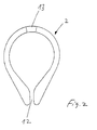
- Fig. 2 shows a sectional view of the suspension element 2, which is formed of a plastic material.
- the suspension element 2 has an oval-shaped, not self-contained cross-section, so that a longitudinally extending opening 12 is formed on its underside, through which a flowing into the suspension element 2 heat transfer medium (warm air) can flow to the outside to textile products or other To dry objects that are held on the suspension element 2.
- the oval-shaped design offers significant advantages in static terms, so that in particular heavier objects such as ski boots to be dried can be held on the suspension element.
- the opening 12 is designed so narrow that the flow rate of the heat transfer medium in the suspension element 2 is kept so high that over the entire, along the suspension element 2 extending outlet opening 12 a uniform outflow of the heat transfer medium can be realized.
- even drying of the textile products held on the suspension element 2 can be realized.
- the outlet opening 12 may accordingly be slot-shaped, that is to say in the form of a slot extending along the suspension element 2.
- the outlet opening 12 can also be formed by a plurality of bores or elongated holes distributed in the longitudinal direction of the suspension element 2.
- the outlet opening 12 may be formed as a sieve or perforated plate.
- a further, but smaller opening 13 is provided, through which the heat transfer medium for the drying of textile materials or other objects is removed upwards.
- a plurality of openings 13 or even a sieve / grid can be provided.
- FIG. 3 shows a sectional view of a further suspension element 2, which is formed from a metallic material, preferably sheet steel, and is formed with smaller wall thicknesses in comparison to the suspension element 2, which is formed from a plastic material and illustrated in FIG. 2.
Landscapes
- Health & Medical Sciences (AREA)
- Public Health (AREA)
- Accessory Of Washing/Drying Machine, Commercial Washing/Drying Machine, Other Washing/Drying Machine (AREA)
- Treatment Of Fiber Materials (AREA)
Applications Claiming Priority (1)
| Application Number | Priority Date | Filing Date | Title |
|---|---|---|---|
| DE200610012399 DE102006012399B4 (de) | 2006-03-17 | 2006-03-17 | Handtuchtrockner für Freizeitmobile |
Publications (2)
| Publication Number | Publication Date |
|---|---|
| EP1834564A2 true EP1834564A2 (fr) | 2007-09-19 |
| EP1834564A3 EP1834564A3 (fr) | 2009-04-22 |
Family
ID=38069247
Family Applications (1)
| Application Number | Title | Priority Date | Filing Date |
|---|---|---|---|
| EP07005477A Withdrawn EP1834564A3 (fr) | 2006-03-17 | 2007-03-16 | Séchoir de serviette pour véhicule mobile de loisirs |
Country Status (2)
| Country | Link |
|---|---|
| EP (1) | EP1834564A3 (fr) |
| DE (1) | DE102006012399B4 (fr) |
Cited By (6)
| Publication number | Priority date | Publication date | Assignee | Title |
|---|---|---|---|---|
| USD905217S1 (en) | 2018-09-05 | 2020-12-15 | Dometic Sweden Ab | Air conditioning apparatus |
| USD907183S1 (en) | 2016-11-23 | 2021-01-05 | Dometic Sweden Ab | Air conditioning apparatus |
| WO2022011403A1 (fr) | 2020-07-16 | 2022-01-20 | Hermann Thaler | Dispositif et procédé de séchage d'objets textiles |
| US11541821B2 (en) | 2020-03-04 | 2023-01-03 | Faurecia Automotive Seating, Llc | Drying rack |
| US11772452B2 (en) | 2017-11-16 | 2023-10-03 | Dometic Sweden Ab | Air conditioning apparatus for recreational vehicles |
| US12043081B2 (en) | 2019-10-17 | 2024-07-23 | Dometic Sweden Ab | Air conditioning apparatus for recreational vehicles |
Families Citing this family (2)
| Publication number | Priority date | Publication date | Assignee | Title |
|---|---|---|---|---|
| DE102012102129B3 (de) | 2012-03-14 | 2013-07-04 | Jürgen Ummenhofer | Vorrichtung und Verfahren zum Trocknen von textilen Gegenständen |
| DE102013020906B3 (de) * | 2013-12-12 | 2014-10-30 | Jörg Kröbel | Verfahren zum Trocknen textiler Gegenstände |
Family Cites Families (10)
| Publication number | Priority date | Publication date | Assignee | Title |
|---|---|---|---|---|
| US2856700A (en) * | 1956-12-13 | 1958-10-21 | Nathaniel B Wales | Laundry dryer convertible into a coiffure dryer |
| DE2442584A1 (de) * | 1974-09-05 | 1976-03-18 | Klaus A Ing Grad Schink | Elektrisch beheizter warmluft-handtuchtrockner |
| US4094076A (en) * | 1976-11-19 | 1978-06-13 | Baslow Floyd M | Fixture for portable hair dryer |
| DE7906779U1 (de) * | 1979-03-10 | 1980-08-21 | Strelow Geb. Schumacher, Roswitha, 4000 Duesseldorf | Sanitaere ausstattungsarmatur |
| FR2772584B1 (fr) * | 1997-12-23 | 2000-03-03 | Sylvain Aubry | Seche torchons electrique |
| US6189230B1 (en) * | 1999-07-07 | 2001-02-20 | Oasis Global Limited | Electric hand dryer and towel dryer |
| JP2001095717A (ja) * | 1999-10-04 | 2001-04-10 | Fumio Hirata | 帯状物乾燥装置及び方法 |
| JP2001246197A (ja) * | 2000-03-07 | 2001-09-11 | Mitsubishi Electric Home Appliance Co Ltd | 乾燥機 |
| DE10221109B4 (de) * | 2002-05-06 | 2004-03-11 | Ks Siebdruck Service Maschinenbau Gmbh | Vorrichtung zum Trocknen von vorzugsweise biegeschlaffem textilem Trockengut |
| FR2842284B1 (fr) * | 2002-07-12 | 2004-10-01 | Muller Et Cie | Radiateur seche-serviettes soufflant |
-
2006
- 2006-03-17 DE DE200610012399 patent/DE102006012399B4/de not_active Expired - Fee Related
-
2007
- 2007-03-16 EP EP07005477A patent/EP1834564A3/fr not_active Withdrawn
Cited By (7)
| Publication number | Priority date | Publication date | Assignee | Title |
|---|---|---|---|---|
| USD907183S1 (en) | 2016-11-23 | 2021-01-05 | Dometic Sweden Ab | Air conditioning apparatus |
| US11772452B2 (en) | 2017-11-16 | 2023-10-03 | Dometic Sweden Ab | Air conditioning apparatus for recreational vehicles |
| USD905217S1 (en) | 2018-09-05 | 2020-12-15 | Dometic Sweden Ab | Air conditioning apparatus |
| USD944374S1 (en) | 2018-09-05 | 2022-02-22 | Dometic Sweden Ab | Air conditioning apparatus |
| US12043081B2 (en) | 2019-10-17 | 2024-07-23 | Dometic Sweden Ab | Air conditioning apparatus for recreational vehicles |
| US11541821B2 (en) | 2020-03-04 | 2023-01-03 | Faurecia Automotive Seating, Llc | Drying rack |
| WO2022011403A1 (fr) | 2020-07-16 | 2022-01-20 | Hermann Thaler | Dispositif et procédé de séchage d'objets textiles |
Also Published As
| Publication number | Publication date |
|---|---|
| EP1834564A3 (fr) | 2009-04-22 |
| DE102006012399B4 (de) | 2009-01-15 |
| DE102006012399A1 (de) | 2007-09-20 |
Similar Documents
| Publication | Publication Date | Title |
|---|---|---|
| DE10047754B4 (de) | Windschutzeinrichtung für einen offenen Kraftwagen | |
| DE112012002115T5 (de) | Klimaanlage für ein Fahrzeug | |
| DE102015210624A1 (de) | Schienenfahrzeug mit Klimatisierung über Sitze | |
| DE102010001319A1 (de) | Luftdurchlass mit einem Gehäuse sowie ein Deckensegel mit Luftdurchlass | |
| DE102006012399B4 (de) | Handtuchtrockner für Freizeitmobile | |
| WO2012130828A1 (fr) | Volet doté d'un dispositif de retenue | |
| DE10043968A1 (de) | Verfahren zum Klimatisieren von Räumen und Klimadecke | |
| DE2128987B2 (de) | Luftverteiler für Heizung-, Liiftungs- und Klimaanlagen in Fahrzeugen, insbesondere in Omnibussen | |
| DE2935735C2 (de) | Anordnung aus Querstromlüftern und Heizkörper | |
| DE10104907A1 (de) | Klimagerät für ein Kraftfahrzeug | |
| WO2014127962A1 (fr) | Sèche-mains | |
| DE112011101965T5 (de) | Fahrzeug-Klimaanlage | |
| EP1816411A2 (fr) | Dispositif de chauffage d'espace pour une caravane | |
| DE102018008404A1 (de) | Wäschetrockner | |
| DE2328186C2 (de) | Induktionsgerät | |
| DE10229368B4 (de) | Umlufttrockner für Warenbahnen | |
| DE19855497B4 (de) | Bodenquell-Luftkonvektor | |
| DE102019104872A1 (de) | Klimatisierung von Räumen mit Quellluftzuführung und Temperierung | |
| DE102005019578A1 (de) | Vorrichtung zum Heizen durch Fluidzirkulation | |
| EP1319537B1 (fr) | Installation de chauffage ou de climatisation pour véhicule à moteur | |
| DE20200246U1 (de) | Anordnung zur Erzeugung eines Luftschottes | |
| DE8516329U1 (de) | Luftverteiler für Lüftungs- und Klimaanlagen | |
| DE7111624U (de) | Klimaanlage fur Kraftfahrzeuge | |
| DE4220420C2 (de) | Warmluftheizung für einen Kirchenraum | |
| DE60301595T2 (de) | Handtuchtrockner, vom Typ eines Heizlüfters |
Legal Events
| Date | Code | Title | Description |
|---|---|---|---|
| PUAI | Public reference made under article 153(3) epc to a published international application that has entered the european phase |
Free format text: ORIGINAL CODE: 0009012 |
|
| AK | Designated contracting states |
Kind code of ref document: A2 Designated state(s): AT BE BG CH CY CZ DE DK EE ES FI FR GB GR HU IE IS IT LI LT LU LV MC MT NL PL PT RO SE SI SK TR |
|
| AX | Request for extension of the european patent |
Extension state: AL BA HR MK YU |
|
| PUAL | Search report despatched |
Free format text: ORIGINAL CODE: 0009013 |
|
| AK | Designated contracting states |
Kind code of ref document: A3 Designated state(s): AT BE BG CH CY CZ DE DK EE ES FI FR GB GR HU IE IS IT LI LT LU LV MC MT NL PL PT RO SE SI SK TR |
|
| AX | Request for extension of the european patent |
Extension state: AL BA HR MK RS |
|
| AKX | Designation fees paid | ||
| STAA | Information on the status of an ep patent application or granted ep patent |
Free format text: STATUS: THE APPLICATION IS DEEMED TO BE WITHDRAWN |
|
| 18D | Application deemed to be withdrawn |
Effective date: 20091023 |
|
| REG | Reference to a national code |
Ref country code: DE Ref legal event code: 8566 |