EP1834832B1 - Mecanisme a pivot - Google Patents
Mecanisme a pivot Download PDFInfo
- Publication number
- EP1834832B1 EP1834832B1 EP05816802A EP05816802A EP1834832B1 EP 1834832 B1 EP1834832 B1 EP 1834832B1 EP 05816802 A EP05816802 A EP 05816802A EP 05816802 A EP05816802 A EP 05816802A EP 1834832 B1 EP1834832 B1 EP 1834832B1
- Authority
- EP
- European Patent Office
- Prior art keywords
- pivot
- seat
- torsion spring
- spring member
- vehicle
- Prior art date
- Legal status (The legal status is an assumption and is not a legal conclusion. Google has not performed a legal analysis and makes no representation as to the accuracy of the status listed.)
- Expired - Lifetime
Links
Images




Classifications
-
- B—PERFORMING OPERATIONS; TRANSPORTING
- B60—VEHICLES IN GENERAL
- B60N—SEATS SPECIALLY ADAPTED FOR VEHICLES; VEHICLE PASSENGER ACCOMMODATION NOT OTHERWISE PROVIDED FOR
- B60N2/00—Seats specially adapted for vehicles; Arrangement or mounting of seats in vehicles
- B60N2/24—Seats specially adapted for vehicles; Arrangement or mounting of seats in vehicles for particular purposes or particular vehicles
- B60N2/30—Non-dismountable or dismountable seats storable in a non-use position, e.g. foldable spare seats
- B60N2/3002—Non-dismountable or dismountable seats storable in a non-use position, e.g. foldable spare seats back-rest movements
- B60N2/3004—Non-dismountable or dismountable seats storable in a non-use position, e.g. foldable spare seats back-rest movements by rotation only
- B60N2/3009—Non-dismountable or dismountable seats storable in a non-use position, e.g. foldable spare seats back-rest movements by rotation only about transversal axis
- B60N2/3011—Non-dismountable or dismountable seats storable in a non-use position, e.g. foldable spare seats back-rest movements by rotation only about transversal axis the back-rest being hinged on the cushion, e.g. "portefeuille movement"
-
- B—PERFORMING OPERATIONS; TRANSPORTING
- B60—VEHICLES IN GENERAL
- B60N—SEATS SPECIALLY ADAPTED FOR VEHICLES; VEHICLE PASSENGER ACCOMMODATION NOT OTHERWISE PROVIDED FOR
- B60N2/00—Seats specially adapted for vehicles; Arrangement or mounting of seats in vehicles
- B60N2/24—Seats specially adapted for vehicles; Arrangement or mounting of seats in vehicles for particular purposes or particular vehicles
- B60N2/30—Non-dismountable or dismountable seats storable in a non-use position, e.g. foldable spare seats
- B60N2/3038—Cushion movements
- B60N2/304—Cushion movements by rotation only
- B60N2/3045—Cushion movements by rotation only about transversal axis
- B60N2/305—Cushion movements by rotation only about transversal axis the cushion being hinged on the vehicle frame
-
- B—PERFORMING OPERATIONS; TRANSPORTING
- B60—VEHICLES IN GENERAL
- B60N—SEATS SPECIALLY ADAPTED FOR VEHICLES; VEHICLE PASSENGER ACCOMMODATION NOT OTHERWISE PROVIDED FOR
- B60N2/00—Seats specially adapted for vehicles; Arrangement or mounting of seats in vehicles
- B60N2/24—Seats specially adapted for vehicles; Arrangement or mounting of seats in vehicles for particular purposes or particular vehicles
- B60N2/32—Seats specially adapted for vehicles; Arrangement or mounting of seats in vehicles for particular purposes or particular vehicles convertible for other use
- B60N2/34—Seats specially adapted for vehicles; Arrangement or mounting of seats in vehicles for particular purposes or particular vehicles convertible for other use into a bed
-
- F—MECHANICAL ENGINEERING; LIGHTING; HEATING; WEAPONS; BLASTING
- F16—ENGINEERING ELEMENTS AND UNITS; GENERAL MEASURES FOR PRODUCING AND MAINTAINING EFFECTIVE FUNCTIONING OF MACHINES OR INSTALLATIONS; THERMAL INSULATION IN GENERAL
- F16F—SPRINGS; SHOCK-ABSORBERS; MEANS FOR DAMPING VIBRATION
- F16F1/00—Springs
- F16F1/02—Springs made of steel or other material having low internal friction; Wound, torsion, leaf, cup, ring or the like springs, the material of the spring not being relevant
- F16F1/04—Wound springs
- F16F1/041—Wound springs with means for modifying the spring characteristics
-
- E—FIXED CONSTRUCTIONS
- E05—LOCKS; KEYS; WINDOW OR DOOR FITTINGS; SAFES
- E05F—DEVICES FOR MOVING WINGS INTO OPEN OR CLOSED POSITION; CHECKS FOR WINGS; WING FITTINGS NOT OTHERWISE PROVIDED FOR, CONCERNED WITH THE FUNCTIONING OF THE WING
- E05F1/00—Closers or openers for wings, not otherwise provided for in this subclass
- E05F1/08—Closers or openers for wings, not otherwise provided for in this subclass spring-actuated, e.g. for horizontally sliding wings
- E05F1/10—Closers or openers for wings, not otherwise provided for in this subclass spring-actuated, e.g. for horizontally sliding wings for swinging wings, e.g. counterbalance
- E05F1/1008—Closers or openers for wings, not otherwise provided for in this subclass spring-actuated, e.g. for horizontally sliding wings for swinging wings, e.g. counterbalance with a coil spring parallel with the pivot axis
- E05F1/1016—Closers or openers for wings, not otherwise provided for in this subclass spring-actuated, e.g. for horizontally sliding wings for swinging wings, e.g. counterbalance with a coil spring parallel with the pivot axis with a canted-coil torsion spring
-
- E—FIXED CONSTRUCTIONS
- E05—LOCKS; KEYS; WINDOW OR DOOR FITTINGS; SAFES
- E05Y—INDEXING SCHEME ASSOCIATED WITH SUBCLASSES E05D AND E05F, RELATING TO CONSTRUCTION ELEMENTS, ELECTRIC CONTROL, POWER SUPPLY, POWER SIGNAL OR TRANSMISSION, USER INTERFACES, MOUNTING OR COUPLING, DETAILS, ACCESSORIES, AUXILIARY OPERATIONS NOT OTHERWISE PROVIDED FOR, APPLICATION THEREOF
- E05Y2900/00—Application of doors, windows, wings or fittings thereof
- E05Y2900/50—Application of doors, windows, wings or fittings thereof for vehicles
- E05Y2900/53—Type of wing
- E05Y2900/538—Interior lids
-
- F—MECHANICAL ENGINEERING; LIGHTING; HEATING; WEAPONS; BLASTING
- F16—ENGINEERING ELEMENTS AND UNITS; GENERAL MEASURES FOR PRODUCING AND MAINTAINING EFFECTIVE FUNCTIONING OF MACHINES OR INSTALLATIONS; THERMAL INSULATION IN GENERAL
- F16F—SPRINGS; SHOCK-ABSORBERS; MEANS FOR DAMPING VIBRATION
- F16F2236/00—Mode of stressing of basic spring or damper elements or devices incorporating such elements
- F16F2236/08—Torsion
Definitions
- the present invention relates to a pivot mechanism. More particularly, the present invention relates to a pivot mechanism which has a stationary body and a movable body that are relatively pivotally coupled together by hinge coupling, and in which the movable body is connected to a torsion spring member so as to be biased in one of the pivot directions.
- a movable body is hinged to a stationary body that is fixed to a desired position.
- a biasing spring may be provided for assisting this operation.
- the biasing spring include a torsion spring member that is formed to a spiral-shape or a torsion bar-shape. The torsion spring member is positioned at a hinge coupling portion. One end of the torsion spring member is connected to a floor-side member mounted on a vehicle floor, which member constitutes the stationary body.
- the other end of the torsion spring member is connected to a seat-side member mounted on the seat, which member constitutes the movable body. Further, the torsion spring member is assembled in a previously twisted condition, so as to bias the seat in the pivot direction opposite to the gravitational force.
- a biasing force can be exerted to the seat due to restoration of the torsion spring member. Therefore, it is possible to reduce an operation force required for performing such an upward pivot operation.
- the above-mentioned biasing force may function as a resistance force. Therefore, when the seat is operated to be downwardly pivoted, such a downward pivot operation is assisted such that the seat can be prevented from being excessively rapidly downwardly pivoted.
- Patent Document 1 mentioned below discloses an example of the pivot mechanism as described above.
- the present invention has been made in order to solve the above-mentioned problems. It is one object of the present invention to enable control of torque produced by a torsion spring member, so that an operation force required for a pivot operation of a movable body can be substantially stabilized regardless of changes of an angular position of pivot thereof.
- a pivot mechanism of the present invention is constructed as follows.
- a first invention relates to a pivot mechanism which includes a stationary body fixed to a desired position, a movable body coupled to the stationary body by hinge coupling so as to be pivotable within a predetermined angle range, and a torsion spring member arranged to bias the movable body in a pivot direction opposite to the gravitational force acting on the movable body.
- the pivot mechanism is constructed such that gravitational moments about a pivot center acting on the movable body can be changed depending on pivoting thereof.
- the torsion spring member has a biasing section for biasing the movable body and a support section supported on the stationary body.
- the support section is positioned at a position between a pivot trajectory of the biasing section produced by pivoting of the pivot mechanism and the pivot center of the pivot mechanism.
- the torsion spring member may include spring members generating torque that can change depending upon the twist angle thereof, e.g., a coil spring, a spiral spring and a torsion spring. According to the first invention, when the movable body pivots about the pivot center, a rate of change of a pivot angle thereof and a rate of change of the twist angle of the torsion spring member are always different from each other.
- the rate of change of the pivot angle of the movable body is greater than the rate of change of the twist angle of the torsion spring member and a region in which the former is smaller than the latter.
- the rate of change of the twist angle of the torsion spring member may change in a curve with respect to the change of the pivot angle of the movable body. That is, torque generated by the torsion spring member changes in a curve with respect to the change of the pivot angle of the movable body.
- the shape of the curve may change depending on an arrangement of the support section and the biasing section of the torsion spring member. Therefore, by changing the arrangement of these sections, the shape of the curve of the torque generated by the torsion spring member can be approximated to a change curve of the gravitational moments acting on the movable body.
- a second invention relates to the first invention described above, in which the support section of the torsion spring member is disposed in a position closer to the pivot center than the biasing section. According to the second invention, a difference between a distance from the support section to the biasing section of the torsion spring member and a distance from the pivot center to the biasing section can be reduced. As a result, a difference between the rate of change of the pivot angle of the movable body and the rate of change of the twist angle of the torsion spring member is also reduced. In addition, the curve of the torque generated by the torsion spring member has a relatively gentle curved shape.
- a third invention relates to the first invention described above, in which the pivot mechanism is a mechanism for pivoting a vehicle seat with respect to a vehicle floor or a mechanism for pivoting a movable component of the vehicle seat.
- the pivot mechanism is a mechanism for pivoting a vehicle seat with respect to a vehicle floor or a mechanism for pivoting a movable component of the vehicle seat.
- a pivot operation of the vehicle seat with respect to the vehicle floor or a pivot operation of the movable component can be performed by the pivot mechanism.
- a fourth invention relates to the second invention described above, in which the pivot mechanism is a mechanism for pivoting a vehicle seat with respect to a vehicle floor or a mechanism for pivoting a movable component of the vehicle seat.
- the pivot mechanism is a mechanism for pivoting a vehicle seat with respect to a vehicle floor or a mechanism for pivoting a movable component of the vehicle seat.
- a pivot operation of the vehicle seat with respect to the vehicle floor or a pivot operation of the movable component can be performed by the pivot mechanism.
- a fifth invention relates to the third invention described above, in which the movable body is a seat-side member fixed to the vehicle seat, wherein the stationary body comprises a floor-side member fixed to the vehicle floor, wherein the vehicle seat can be changed to a folded posture in which the seat back is folded onto a seat cushion by a reclining mechanism for controlling an inclination angle of a seat back, and wherein the vehicle seat is pivoted with respect to the vehicle floor in the folded condition.
- a pivot operation of a heavy object i.e., the vehicle seat in the folded posture, can be performed via the pivot mechanism.
- a sixth invention relates to the fourth invention described above, in which the movable body is a seat-side member fixed to the vehicle seat, wherein the stationary body comprises a floor-side member fixed to the vehicle floor, wherein the vehicle seat can be changed to a folded posture in which the seat back is folded onto a seat cushion by a reclining mechanism for controlling an inclination angle of a seat back, and wherein the vehicle seat is pivoted with respect to the vehicle floor in the folded condition.
- a pivot operation of a heavy object i.e., the vehicle seat in the folded posture, can be performed via the pivot mechanism.
- a seventh invention relates to the fifth invention described above, in which the torsion spring member is a spiral spring.
- the torsion spring member composed of the spiral spring has a spiral configuration that is not spread in the axial direction. Therefore, the torsion spring member can be arranged compactly in the axial direction.
- An eighth invention relates to the sixth invention described above, in which the torsion spring member is a spiral spring.
- the torsion spring member composed of the spiral spring has a spiral configuration that is not spread in the axial direction. Therefore, the torsion spring member can be arranged compactly in the axial direction.
- the present invention thus constructed may provides the following effects.
- the torque generated by the torsion spring member can be changed in a curve with respect to the change of the pivot angle of the movable body. Therefore, as compared with a case in which the generated torque of the torsion spring member changes linearly, the generated torque curve can be easily controlled to approximate a curve of the gravitational moment acting on the movable body. That is, an operation force required for a pivot operation of the movable body can be easily controlled to be substantially stabilized regardless of changes of an angular position of pivot thereof. Further, according to the second invention, the generated torque curve of the torsion spring member can be controlled so as to have a relatively gentle shape.
- the pivot operation of the vehicle seat with respect to the vehicle floor or the pivot operation of the movable component can be performed with a substantially constant small force via the pivot mechanism.
- the pivot operation of the vehicle seat with respect to the vehicle floor or the pivot operation of the movable component can be performed with a substantially constant small force via the pivot mechanism.
- the pivot operation of a heavy object, i.e., the vehicle seat in the folded posture can be performed with a substantially constant small force via the pivot mechanism.
- the pivot operation of a heavy object i.e., the vehicle seat in the folded posture
- the pivot operation of a heavy object can be performed with a substantially constant small force via the pivot mechanism.
- the torsion spring member can be compactly adapted in a width direction of the vehicle seat.
- the torsion spring member can be compactly adapted in a width direction of the vehicle seat.
- FIG. 1 is a view illustrating an appearance of a vehicle seat 1.
- FIG. 2 is a view illustrating a construction of tumble mechanisms 10A.
- FIG. 3 is a view schematically illustrating a relation between a pivot angle ⁇ and a twist angle ⁇ .
- FIG 4 is a view illustrating a relation between the twist angle ⁇ of a torsion spring member 14 and torque T generated thereby.
- FIG. 5 is a view illustrating a relation between the pivot angle ⁇ and respective action moments. Further, in a plane of FIGS.
- a left-hand direction corresponds to a forward direction of a vehicle
- an upward direction corresponds to an upward direction of the vehicle.
- the pivot mechanism of this embodiment is formed as the tumble mechanisms 10A for upwardly pivoting the vehicle seat 1 (hereinafter simply referred to as seat 1) toward a retracted position in the front of the vehicle under a condition that a seat back 3 is folded onto a seat cushion 2.
- a front side of the seat 1 is supported by the tumble mechanisms 10A provided on a vehicle floor F, and a rear side of the seat 1 is supported by lock mechanisms 20.
- a lower end portion of the seat back 3 is supported by a reclining mechanism 30A provided to a rear end of the seat cushion 2, so as to be rotated about a pivot center 31.
- the reclining mechanism 30A supports the seat back 3 such that an inclination angle of the seat back 3 can be controlled.
- the seat back 3 can be moved to a raised posture in which it is raised with respect to the seat cushion 2 or to a folded posture (the state shown by broken lines of FIG. 1 ) in which it is folded onto the seat cushion 2.
- the tumble mechanisms 10A correspond to a pivot mechanism of the present invention.
- the tumble mechanisms 10A may include a pair of right and left tumble mechanisms 10A that are provided to the front side of the seat cushion 2.
- each of the tumble mechanisms 10A has a member fixed to the vehicle floor F (a floor-side member B), a member fixed to the lower surface of the seat cushion 2 (a seat-side member 12), and a hinge portion 13 that connects these two members so as to pivot relative to each other.
- the seat-side member 12 can pivot about a pivot center 13a of the hinge portion 13 so as to be pivoted upwardly and downwardly.
- the pivoting range of the seat 1 corresponds to a range between a pivot start position De1 (the position shown by broken lines) in which the seat 1 is downwardly pivoted so as to be positioned on the vehicle floor F and a pivot end position Ar1 (the position shown by solid lines) in which the seat 1 is upwardly pivoted by 90 degrees toward the forward direction of the vehicle.
- a pivot start position De1 the position shown by broken lines
- Ar1 the position shown by solid lines
- this pivoting range is restricted by engaging an engagement portion 12b formed in the seat-side member 12 with a stopper Bs formed in the floor-side member B when the seat 1 is pivoted to the pivot end position Ar1 (the position shown by solid lines). Further, the engagement portion 12b is positioned at a leading end of pivot of the seat-side member 12. Further, in FIG 2 , conditions respectively corresponding to the pivot start position De1 of the seat 1 and an intermediate position of pivot of the seat 1 are shown by broken lines.
- each of the tumble mechanisms 10A is provided with a torsion spring member 14 which biases the seat-side member 12 counterclockwise in FIG 2 , i.e., in the direction toward the pivot end position Ar1 from the pivot start position De1.
- the torsion spring member 14 is a known spiral spring. That is, the torsion spring member 14 has a spiral configuration that is aligned with a direction perpendicular to the axial direction. Therefore, the torsion spring member 14 has a compact configuration that does not occupy much space in the axial direction.
- the core end of the torsion spring member 14 is formed as a support section 14a that is attached to the floor-side member B.
- the support section 14a may function as a center of twist of the torsion spring member 14.
- the outer end portion of the torsion spring member 14 is formed as a biasing section 14b mounted to the seat-side member 12.
- spring members other than the spiral spring described above can be used as the torsion spring member 14.
- Examples of usable spring members may include a known coil spring having a spiral configuration that extends along the axial direction and a spring member generating torque that can change depending upon the twist angle thereof, e.g., a torsion bar-shaped torsion spring.
- the torsion spring member 14 is positioned such that the support section 14a or the core end portion thereof is outwardly spaced apart in a radial direction (the direction perpendicular to the axial direction) from the pivot center 13a of the hinge portion 13.
- the support section 14a is integrally attached to the floor-side member B.
- the biasing section 14b or the outer pivoting end engages a protruding engagement pin 12a that is integrally provided to the seat-side member 12.
- the biasing section 14b is formed as a hook-shaped bent portion that can engage the engagement pin 12a from below in a scooping up manner.
- the torsion spring member 14 is assembled in a previously twisted condition, so as to bias the biasing section 14b counterclockwise in FIG. 2 .
- the biasing section 14b normally biases the seat-side member 12 counterclockwise with respect to the floor-side member B.
- the above-mentioned support section 14a is disposed within a pivoting range between the pivot start position De1 and the pivot end position Ar1 in which the biasing section 14b pivots about the pivot center 13a.
- the support section 14a is disposed in an intermediate position between the pivot center 13a and the biasing section 14b when the biasing section 14b pivots by 45 degrees from the pivot start position De1 (the position shown by the broken lines in FIG. 2 ).
- FIG. 3 shows how the twist angle ⁇ of the torsion spring member 14 changes.
- the pivot angle ⁇ means the pivot angle of the biasing section 14b about the pivot center 13a.
- the twist angle ⁇ means the pivot angle (a twist angle) of the biasing section 14b about the support section 14a of the torsion spring member 14.
- Each of the pivot angle ⁇ and the twist angle ⁇ is defined as a clockwise angular deviation of the biasing section 14b from the pivot end position Ar1 which corresponds to 0 degrees.
- the solid plot dots in this drawing indicate the pivoting positions of the biasing section 14b, which positions correspond to 10 degrees increments of the pivot angle ⁇ .
- the pivot angle ⁇ may have a pivot range up to 90 degrees, whereas the twist angle ⁇ may have a pivot range greater than 90 degrees.
- the pivot range of the twist angle ⁇ is theoretically 147.4 degrees.
- the rate of change of the pivot angle ⁇ of the biasing section 14b and the rate of change of the twist angle ⁇ are always different from each other. In particular, when the biasing section 14b is positioned at pivot regions closer to the pivot start position De1 and the pivot end position Ar1, the rate of change of the twist angle ⁇ is smaller than the rate of change of the pivot angle ⁇ . Conversely, when the biasing section 14b is positioned at a pivoting region closer to 45 degrees, the rate of change of the twist angle ⁇ is larger than the rate of change of the pivot angle ⁇ .
- FIG. 4 shows the relation between the twist angle ⁇ of the torsion spring member 14 and the generated torque T.
- the relation as shown in FIG. 4 corresponds to the properties of a commonly used torsion spring member. That is, the generated torque T generated by the torsion spring member 14 may linearly change with the change of the twist angle ⁇ due to the relation with its spring constant.
- the generated torque T generated by the spring member 14 when converted based on the rate of change of the pivot angle ⁇ , does not linearly change as stated above and instead changes in a curve as represented by a generated torque curve Tc1 indicated by the solid line of FIG. 5 .
- the solid plot dots in this drawing correspond to the solid plot dots shown in FIGS.
- these dots represent the generated torque T of the torsion spring member 14 corresponding to the 10 degrees increments of the pivot angle ⁇ .
- the generated torque T represented by the solid plot dots corresponds to values of the torque generated about the pivot center 13a of the torsion spring member 14.
- the open plot dots represent the generated torque T generated around the support section 14a of the torsion spring member 14.
- the generated torque T may linearly change with the change of the pivot angle ⁇ .
- the relation between the generated torque T indicated by the open plot dots and the generated torque T indicated by the solid plot dots can be explained with reference to FIG. 3 . That is, first, the generated torque T indicated by the open plot dots in FIG.
- a gravitational moment curve Mc1 indicated by a dashed line represents a change in gravitational moments M about the pivot center 13a of the seat 1.
- the gravitational moments M correspond to moment values about the pivot center 13a (a distance L3) of a center of gravity G of the seat 1 including the seat-side member 12.
- the shape of each of the generated torque curve Tc1 and the gravitational moment curve Mc1 shown in FIG. 5 is an example.
- the shape thereof can be changed by changing setting conditions, e.g., a spring constant of the torsion spring member 14 and an arrangement (the ratio of the distance L1 to the distance L2) of the support section 14a.
- the shape thereof can be changed by changing setting conditions, e.g., a weight of the seat 1 and a position of the center of gravity (the distance L3).
- setting conditions e.g., a weight of the seat 1 and a position of the center of gravity (the distance L3).
- the shapes of the two curves can be approximated to each other by determining each of the setting conditions described above.
- the generated torque curve Tc1 is somewhat below the gravitational moment curve Mc1 in a region adjacent to the pivot start position De1 and the pivot end position Ar1.
- the generated torque curve Tc1 is somewhat above the gravitational moment curve Mc1 in a middle region between these end positions (45 degrees).
- the seat 1 in order to upwardly pivot the seat 1, it is necessary for a user to apply a pivot operation force to the seat to compensate for the shortage of the generated torque T of the torsion spring member 14.
- the seat 1 in the latter, that is, in the region in which the generated torque curve Tc1 is above the gravitational moment curve Mc1, the seat 1 can be automatically upwardly pivoted without the pivot operation force of the user. That is, in both of the regions described above, the operation force required for pivoting the seat 1 upwardly and downwardly can be reduced.
- the shapes of the two curves are close to each other, changes of the required operation force are minimized.
- the seat 1 when the seat 1 is positioned at the pivot start position De1, the seat 1 cannot be automatically upwardly pivoted. Therefore, the seat 1 can be immovably retained on the vehicle floor F. That is, the seat 1 positioned at the pivot start position De1 can be prevented from spontaneously moving upwardly. As a result, the seat 1 can be prevented from rattling.
- the lock mechanisms 20 may include a pair of right and left lock mechanisms 20 that are provided to the rear side of the seat cushion 2.
- Each of the lock mechanisms 20 has a hook 21 that can engage a gate-shaped striker S fixed to the vehicle floor F.
- the hook 21 is constructed to be protruded and retracted with respect to a jaw-shaped main body of the lock mechanism 20 and is normally biased in the protruding direction so as to engage the striker S.
- the hook 21 can engage the striker S, so that the rear side portion of the seat cushion 2 can be locked to the vehicle floor F.
- an upward pivot operation of the seat 1 can be prohibited.
- the lock condition of the lock mechanism 20 thus produced can be released by a release operation of an operation lever (not shown).
- the hook 21 is moved to a retracted position so as to be disengaged from the striker S.
- the lock mechanism 20 is provided with a clearance (play) that permits some amount of movement in the upward pivot direction of the seat 1 even if the hook 21 engages the striker S. As a result, the seat 1 can be moved upwardly from the vehicle floor F within a range corresponding to the clearance of the lock mechanism 20.
- the seat 1 can be prevented from automatically upwardly pivoting by the biasing force of the torsion spring member 14 when the seat is positioned at the region closer to the pivot start position De1. Therefore, the seat 1 can be immovably retained on the vehicle floor F. This configuration reduces the possibility of when a passenger sits on the seat 1, the seat 1 could possibly fall toward and impact the vehicle floor F because the seat 1 cannot move upwardly from the vehicle floor F within the range corresponding to the clearance.
- the seat 1 is positioned at the pivot start position De1 in a folded condition.
- each of the lock mechanisms 20 engages the striker S, so that the seat 1 is locked to the vehicle floor F.
- the release operation of the operation lever (not shown) is performed, thereby releasing the lock mechanism 20.
- the seat 1 is pivoted in the upward pivot direction thereof.
- the seat 1 is upwardly pivoted while it is pivoted about the pivot center 13a.
- the upward pivot operation of the seat 1 can be performed with a relatively small force.
- the seat 1 When the seat 1 is upwardly pivoted to a certain degree (an angle of around 45 degrees), the seat 1 is automatically upwardly pivoted by the biasing force of the torsion spring member 14. After the seat 1 is upwardly pivoted to a position closer to the pivot end position Ar1, the seat 1 can be upwardly pivoted to the pivot end position Ar1 when a small pivot operation force is applied thereto by the user. Thus, the seat 1 can be retracted to the retracted position (the position shown by the solid lines). Further, the seat 1 that is positioned at the retracted position can be downwardly pivoted onto the vehicle floor F by performing procedures reverse to the procedures described above. That is, the seat 1 is downwardly pivoted while the small force is applied thereto by the user. As a result, the seat 1 is moved on the vehicle floor F. At this time, the lock mechanism 20 automatically engage the striker S, so that the seat 1 is locked to the vehicle floor F.
- the generated torque T of the torsion spring member 14 can be changed in a curve with respect to the change of the pivot angle ⁇ of the seat 1. Therefore, as compared with a case in which the generated torque of the torsion spring member 14 changes linearly, the generated torque curve Tc1 can be easily controlled to approximate the gravitational moment curve Mc1. That is, the operation force required for the pivot operation of the seat 1 can be easily controlled to be substantially stabilized regardless of changes of an angular position of pivot thereof. Also, according to the present pivot mechanism, a heavy object such as the seat 1 in this embodiment can be pivoted with a substantially constant small force.
- the seat 1 when the seat 1 is upwardly pivoted to the position closer to the pivot end position Ar1, the generated torque T is less than the gravitational moments M. Therefore, the seat 1 can be upwardly pivoted while it is prevented from being excessively rapidly upwardly pivoted. Further, when the seat 1 is positioned closer to the pivot start position De1, the generated torque T is also less than the gravitational moments M. Therefore, the seat 1 can be prevented from spontaneously moving upwardly. As a result, the seat 1 can be prevented from rattling on the vehicle floor F. Further, since the torsion spring member 14 is composed of the spiral spring, it can be compactly positioned in a width direction of the seat 1.
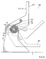
- FIG. 6 is a view illustrating a construction of a tumble mechanism 10B.
- FIG. 7 is a view schematically illustrating a relation between a pivot angle ⁇ and a twist angle ⁇ .
- FIG. 8 is a view illustrating a relation between the pivot angle ⁇ and respective action moments.
- elements that have substantially the same construction and operation as those of the pivot mechanism (the tumble mechanisms 10A) of the first embodiment will be identified by the same reference numerals and a description of such elements may be omitted. As best shown in FIG.
- the support section 14a of the torsion spring member 14 is disposed in a position that is closer to the pivot center 13a.
- the support section 14a is positioned at a mid position between the position of the support section 14a of the first embodiment ( FIG. 2 ) and the pivot center 13a. That is, the support section 14a is positioned such that the ratio of the distance between the support section 14a and the pivot center 13a to the distance between the support section 14a and the biasing section 14b is 1:3.
- FIG. 7 shows how the twist angle ⁇ of the torsion spring member 14 changes.
- the difference between the rate of change of the twist angle ⁇ and the rate of change of the pivot angle ⁇ is generally small. Therefore, as best shown in FIG. 8 , as compared with the first embodiment ( FIG 5 ), a generated torque curve Tc2 of the torsion spring member 14 has a gently curved shape that is more approximated to the shape of a gravitational moment curve Mc2. As a result, the difference between the shapes of these two curves may also change gently.
- the seat 1 can be pivoted between a pivot start position De2 and a pivot end position Ar2 with a further stabilized small force.
- FIG. 9 is a view illustrating an appearance of the seat 1.
- FIG. 10 is a view illustrating a relation between a pivot angle ⁇ and respective action moments.
- elements that have substantially the same construction and operation as those of the pivot mechanism (the tumble mechanisms 10A) of the first embodiment will be identified by the same reference numerals and a description of such elements may be omitted.
- a pivot mechanism of this embodiment is constructed as reclining mechanisms 30C for adjusting a tilt angle of the seat back 3.
- the reclining mechanisms 30C connect the seat back 3 as a movable body to the seat cushion 2 as a stationary body, so that the seat back 3 can be pivoted about a pivot center 31.
- the reclining mechanisms 30C may include a pair of right and left reclining mechanisms 30C that are provided to the rear side of the seat cushion 2.
- Each of the reclining mechanism 30C is provided with the torsion spring member 14 that biases the seat back 3 from a pivot start position De3 (a position shown by broken lines) toward a raised position Ar3 (a position shown by solid lines).
- the pivot end position of the reclining mechanism 30C corresponds to a position in which the seat back 3 is folded onto the seat cushion 2 so as to have a folded posture.
- the torsion spring member 14 is disposed between the seat cushion 2 and the seat back 3 in the same manner as the first embodiment, as shown in FIG. 2 .
- the support section 14a or the core end portion of the torsion spring member 14 is attached to the seat cushion 2.
- the biasing section 14b or the outer end portion of the torsion spring member 14 is attached to the seat back 3.
- the support section 14a is disposed in the intermediate position between the pivot center 31 and the biasing section 14b when the biasing section 14b pivots by 45 degrees from the pivot start position De3.
- a generated torque curve Tc3 of the torsion spring member 14 of this embodiment is determined in a curved shape as shown in FIG. 10 . That is, the generated torque curve Tc3 is determined such that the generated torque T is acted in the rotational direction that the seat back 3 is folded forwardly even if the seat back 3 is in a position in which the pivot angle ⁇ is 0 degrees (the raised position Ar3). This determination can be performed by controlling the initial twisting amount of the torsion spring member 14. As will be seen from this drawing, in the region adjacent to the pivot start position De3, the generated torque curve Tc3 is below a gravitational moment curve Mc3.
- the generated torque curve Tc3 is above the gravitational moment curve Mc3. Therefore, when the seat back 3 is positioned at the pivot start position De3, the seat back 3 cannot be automatically upwardly pivoted. Thus, the seat back 3 positioned at the pivot start position De3 is immovably retained in the pivot position. Further, when the seat back 3 is once upwardly pivoted by manual operation or the like, the seat back 3 can be automatically raised by the biasing force of the torsion spring member 14. In this case, because the generated torque curve Tc3 is somewhat above the gravitational moment curve Mc3, the seat back 3 can be raised while it is prevented from being excessively rapidly pivoted.
- the seat back 3 is gently raised until the seat back 3 reaches the erect attitude position Ar3. Thereafter, the seat back 3 is folded onto the seat cushion 2, so that the seat 1 can be changed to the folded condition. Further, the seat back 3 positioned at the folded condition can be rearwardly pivoted to the pivot start position De3 by performing procedures reverse to the procedures described above. That is, when the seat back 3 is rearwardly tilted while the small force is applied thereto, the seat back 3 can be moved to the pivot start position De3.
- the seat back 3 of the seat 1 as a movable component can be pivoted with a substantially stabilized small operation force. Also, the seat back 3 can be prevented from being excessively rapidly pivoted.
- the present pivot mechanism is embodied as the tumble mechanisms for upwardly pivoting the seat in the forward direction of the vehicle.
- the present pivot mechanism can be embodied as tumble mechanisms for upwardly pivoting the seat in the rearward or sideward direction of the vehicle.
- the present pivot mechanism can be embodied as mechanisms for downwardly pivoting the seat in the forward, rearward or sideward direction of the vehicle.
- the present pivot mechanism can be embodied as mechanisms for pivoting the movable component, e.g., an arm rest that is pivotally attached to the seat.
- the present pivot mechanism can be applied to articles other than the vehicle seat.
- the present pivot mechanism can be used as various types of pivot mechanisms, e.g., mechanisms for pivoting a door.
- the position of the support section of the torsion spring member is not limited to the positions in the first and second embodiments.
- the support section can be positioned closer to the biasing section.
- the angular position of the support section is not limited to the special angular position of 45 degrees between the pivot start position and the pivot end position. That is, the support section can be positioned at desired angular positions.
Landscapes
- Engineering & Computer Science (AREA)
- Mechanical Engineering (AREA)
- Aviation & Aerospace Engineering (AREA)
- Transportation (AREA)
- General Engineering & Computer Science (AREA)
- Seats For Vehicles (AREA)
- Pivots And Pivotal Connections (AREA)
Claims (8)
- Un mécanisme de pivotement comprenant :un corps stationnaire fixé à une position souhaitée ;un corps déplaçable couplé au corps stationnaire par une liaison à charnière de manière à être pivotable dans une plage angulaire prédéterminée ; etun organe formant ressort de torsion agencé pour solliciter le corps déplaçable selon une direction de pivotement opposée à la force de gravité agissant sur le corps déplaçable,le mécanisme de pivotement étant construit de telle sorte que des couples de force de gravité autour d'un centre de pivotement agissant sur le corps déplaçable puissent être variées en fonction de son pivotement,l'organe formant ressort de torsion présentant une partie de sollicitation pour solliciter le corps déplaçable et une partie de support qui est supportée sur le corps stationnaire, etla partie de support étant positionnée à une position entre une trajectoire de pivotement de la partie de sollicitation résultant du pivotement du mécanisme de pivotement et le centre de pivotement du mécanisme de pivotement.
- Le mécanisme de pivotement selon la revendication 1, dans lequel la partie de support de l'organe formant ressort de torsion est disposée dans une position qui est plus proche du centre de pivotement que la partie de sollicitation.
- Le mécanisme de pivotement selon la revendication 1, dans lequel le mécanisme de pivotement comprend un mécanisme permettant le pivotement d'un siège de véhicule par rapport à un plancher de véhicule ou un mécanisme permettant le pivotement d'un composant déplaçable du siège de véhicule.
- Le mécanisme de pivotement selon la revendication 2, dans lequel le mécanisme de pivotement comprend un mécanisme permettant le pivotement de siège de véhicule par rapport à un plancher du véhicule ou un mécanisme permettant le pivotement d'un composant déplaçable du siège de véhicule.
- Le mécanisme de pivotement selon la revendication 3, dans lequel le corps déplaçable comprend un organe de côté du siège fixé au siège du véhicule, le corps stationnaire comprenant un organe de côté du plancher fixé au plancher du véhicule, le siège de véhicule pouvant être modifié pour une position pliée dans laquelle le dossier de siège est rabattu sur un coussin de siège au moyen d'un mécanisme de réglage pour régler un angle d'inclinaison d'un dossier de siège, et le siège de véhicule étant pivoté par rapport au plancher de véhicule dans la condition pliée.
- Le mécanisme de pivotement selon la revendication 4, dans lequel le corps déplaçable comprend un organe de côté du siège fixé au siège du véhicule, le corps stationnaire comprenant un organe de côté du plancher fixé au plancher du véhicule, le siège de véhicule pouvant être modifié pour une position pliée dans laquelle le dossier de siège est rabattu sur un coussin de siège au moyen d'un mécanisme de réglage pour régler un angle d'inclinaison d'un dossier de siège, et le siège de véhicule étant pivoté par rapport au plancher de véhicule dans la condition pliée.
- Le mécanisme de pivotement selon la revendication 5, dans lequel l'organe formant ressort à torsion comprend un ressort hélicoïdal.
- Le mécanisme de pivotement selon la revendication 6, dans lequel l'organe formant ressort à torsion comprend un ressort hélicoïdal.
Applications Claiming Priority (2)
| Application Number | Priority Date | Filing Date | Title |
|---|---|---|---|
| JP2005000087 | 2005-01-04 | ||
| PCT/JP2005/022849 WO2006073044A1 (fr) | 2005-01-04 | 2005-12-13 | Mecanisme a pivot |
Publications (3)
| Publication Number | Publication Date |
|---|---|
| EP1834832A1 EP1834832A1 (fr) | 2007-09-19 |
| EP1834832A4 EP1834832A4 (fr) | 2009-02-25 |
| EP1834832B1 true EP1834832B1 (fr) | 2010-06-02 |
Family
ID=36647529
Family Applications (1)
| Application Number | Title | Priority Date | Filing Date |
|---|---|---|---|
| EP05816802A Expired - Lifetime EP1834832B1 (fr) | 2005-01-04 | 2005-12-13 | Mecanisme a pivot |
Country Status (6)
| Country | Link |
|---|---|
| US (1) | US7878595B2 (fr) |
| EP (1) | EP1834832B1 (fr) |
| JP (1) | JP4775266B2 (fr) |
| CN (1) | CN100537296C (fr) |
| DE (1) | DE602005021700D1 (fr) |
| WO (1) | WO2006073044A1 (fr) |
Families Citing this family (18)
| Publication number | Priority date | Publication date | Assignee | Title |
|---|---|---|---|---|
| US20080022882A1 (en) * | 2006-07-26 | 2008-01-31 | Western-Cullen-Hayes, Inc. | Hinged derail with assisted manual lifting and method for constructing |
| FR2931736B1 (fr) * | 2008-05-29 | 2010-10-08 | Tachi S Co | Structure de siege rabattable, notamment pour vehicule automobile |
| JP5181866B2 (ja) * | 2008-06-24 | 2013-04-10 | トヨタ紡織株式会社 | 車両用シートの切換機構 |
| JP5511294B2 (ja) * | 2009-10-07 | 2014-06-04 | テイ・エス テック株式会社 | 車両用シートの収納補助装置 |
| TW201224314A (en) * | 2010-12-01 | 2012-06-16 | Bo-Sen Xiao | Gravity compensation device |
| JP5914009B2 (ja) * | 2012-01-25 | 2016-05-11 | 中央発條株式会社 | 渦巻ばね |
| WO2015037052A1 (fr) * | 2013-09-10 | 2015-03-19 | 本田技研工業株式会社 | Dispositif de siège type strapontin pour véhicule |
| US9970697B2 (en) * | 2014-09-12 | 2018-05-15 | Whirlpool Corporation | Multi-part icemaker bail arms and icemakers |
| US9586503B1 (en) * | 2015-08-28 | 2017-03-07 | Faurecia Automotive Seating Llc | Vehicle seat and torsion bar |
| US20190308565A1 (en) * | 2016-11-18 | 2019-10-10 | Huf North America Automotive Parts Manufacturing Corp. | Deployable sensor assembly |
| US10752133B2 (en) * | 2017-05-12 | 2020-08-25 | Magna Seating Inc | Multidirectional clock spring with rotating arbor |
| JP7170393B2 (ja) * | 2017-12-27 | 2022-11-14 | 株式会社エンプラス | 開閉体の開閉機構 |
| EP3977904B1 (fr) | 2019-03-11 | 2022-10-12 | Storyteller Overland, LLC | Système de modification de véhicule de plaisance |
| US11958585B1 (en) | 2020-11-25 | 2024-04-16 | Ltag Systems Llc | Midair deployment of aerostats |
| US11866196B1 (en) * | 2021-06-03 | 2024-01-09 | Ltag Systems Llc | Payload deployment from aerostats |
| TWI819595B (zh) * | 2022-05-05 | 2023-10-21 | 緯創資通股份有限公司 | 光學檢測裝置 |
| US12429311B1 (en) | 2023-02-07 | 2025-09-30 | Ltag Systems Llc | Aerostats for aerial platform acquisition |
| US12275516B1 (en) | 2023-02-21 | 2025-04-15 | Ltag Systems Llc | Stabilization and reinforcement of balloons during rapid filling |
Family Cites Families (32)
| Publication number | Priority date | Publication date | Assignee | Title |
|---|---|---|---|---|
| US478131A (en) * | 1892-07-05 | Arthur m | ||
| US376886A (en) * | 1888-01-24 | Joseph beeakley holder | ||
| JPS5315528Y2 (fr) * | 1972-05-05 | 1978-04-24 | ||
| GB1436134A (en) * | 1973-08-22 | 1976-05-19 | Turner Willenhall Ltd H R | Vehicle seats |
| JPS6253055A (ja) | 1985-10-16 | 1987-03-07 | Sony Corp | 留守番電話装置 |
| US4756577A (en) * | 1987-04-13 | 1988-07-12 | General Motors Corporation | Lock mechanism for a car seat back and recliner |
| US5205610A (en) * | 1991-10-07 | 1993-04-27 | Reninger Donald J | Folding seat |
| JPH067548A (ja) | 1992-06-27 | 1994-01-18 | Takashi Kanai | 航行体の高度制御装置 |
| US5547254A (en) * | 1992-09-30 | 1996-08-20 | Aisin Seiki Kabushiki Kaisha | Pawl and ratchet type seat tilt control apparatus |
| US5390980A (en) * | 1993-02-10 | 1995-02-21 | Bertrand Faure Ltd. | Zero chuck vehicle seat latching mechanism |
| US5558403A (en) * | 1995-01-23 | 1996-09-24 | Atoma International, Inc. | Seat recliner |
| FR2741571B1 (fr) * | 1995-11-29 | 1998-02-06 | Cesa | Siege pour vehicule automobile muni d'une commande d'articulation de dossier perfectionnee |
| JP3313590B2 (ja) * | 1996-09-30 | 2002-08-12 | 富士機工株式会社 | シートリクライニング装置 |
| JPH1199859A (ja) | 1997-09-29 | 1999-04-13 | Nhk Spring Co Ltd | 自動車用座席 |
| CN2320455Y (zh) * | 1998-01-09 | 1999-05-26 | 邹耀忠 | 卧铺调角器 |
| WO1999059836A1 (fr) * | 1998-05-15 | 1999-11-25 | Magna Interior Systems Inc. | Ensemble support de siege a pliage et culbute |
| JP2000102438A (ja) * | 1998-07-30 | 2000-04-11 | Chuo Spring Co Ltd | 衝撃緩和装置 |
| US6199953B1 (en) * | 1999-05-18 | 2001-03-13 | Fisher Dynamics Corporation | Sector recliner with single position memory |
| US6179363B1 (en) * | 1999-05-27 | 2001-01-30 | Daimlerchrysler Corporation | Transportable vehicle seat |
| US6220664B1 (en) * | 1999-08-26 | 2001-04-24 | Ming-Hao Lee | Base structure for chair seat |
| JP3903661B2 (ja) * | 1999-09-17 | 2007-04-11 | スズキ株式会社 | 折りたたみシートの回動ロック構造 |
| GB2358132B (en) * | 2000-01-14 | 2003-12-31 | Autoliv Dev | A recliner mechanism for a vehicle seat |
| US6502903B2 (en) * | 2001-01-11 | 2003-01-07 | Bae Industries, Inc. | Seat integrated latch recliner assembly with inertial locking mechanism |
| DE10126001A1 (de) * | 2001-05-18 | 2002-11-21 | Bock 1 Gmbh & Co | Vorgespannte Federanordnung, insbesondere zur Federbeaufschlagung von Synchronmechaniken von Bürostühlen |
| US6789849B2 (en) * | 2001-05-23 | 2004-09-14 | Porter Engineered Systems, Inc. | Fold-flat seat reclining and locking mechanism |
| US6601921B1 (en) * | 2001-08-29 | 2003-08-05 | Fisher Dynamics Corporation | Seatback latch release mechanism with safety capture |
| US6659554B2 (en) * | 2002-02-01 | 2003-12-09 | Wen-Fa Su | Adjustment device of a chair backrest |
| JP3746249B2 (ja) | 2002-06-17 | 2006-02-15 | 日本テクニカ株式会社 | シートリクライニング装置 |
| DE10228940C1 (de) | 2002-06-28 | 2003-06-26 | Faurecia Autositze Gmbh & Co | Vorrichtung zum klappbaren Anlenken eines Kraftfahrzeugsitzes an einer Karosserie |
| US7344195B2 (en) * | 2005-02-11 | 2008-03-18 | Lear Corporation | Dampener for a vehicle seat recliner |
| JP5002160B2 (ja) * | 2006-01-26 | 2012-08-15 | 中央発條株式会社 | 渦巻ばねアセンブリおよび外内端荷重の制御方法 |
| JP4917814B2 (ja) * | 2006-02-23 | 2012-04-18 | 株式会社ソミック石川 | リクライニング装置及びそれを具備する自動車用シート |
-
2005
- 2005-12-13 EP EP05816802A patent/EP1834832B1/fr not_active Expired - Lifetime
- 2005-12-13 JP JP2006550662A patent/JP4775266B2/ja not_active Expired - Fee Related
- 2005-12-13 WO PCT/JP2005/022849 patent/WO2006073044A1/fr not_active Ceased
- 2005-12-13 DE DE602005021700T patent/DE602005021700D1/de not_active Expired - Lifetime
- 2005-12-13 CN CNB2005800457637A patent/CN100537296C/zh not_active Expired - Fee Related
- 2005-12-13 US US11/794,172 patent/US7878595B2/en active Active
Also Published As
| Publication number | Publication date |
|---|---|
| US20080121778A1 (en) | 2008-05-29 |
| US7878595B2 (en) | 2011-02-01 |
| EP1834832A4 (fr) | 2009-02-25 |
| JPWO2006073044A1 (ja) | 2008-06-12 |
| WO2006073044A1 (fr) | 2006-07-13 |
| DE602005021700D1 (de) | 2010-07-15 |
| EP1834832A1 (fr) | 2007-09-19 |
| CN100537296C (zh) | 2009-09-09 |
| JP4775266B2 (ja) | 2011-09-21 |
| CN101094777A (zh) | 2007-12-26 |
Similar Documents
| Publication | Publication Date | Title |
|---|---|---|
| EP1834832B1 (fr) | Mecanisme a pivot | |
| JP5104853B2 (ja) | 車両用シート | |
| US8282150B2 (en) | Vehicle seat stow release system and method | |
| US8123272B2 (en) | Vehicle seat | |
| KR101083118B1 (ko) | 차량용 시트의 조작 레버 | |
| US8141954B2 (en) | Switching mechanisms of vehicle seats | |
| US7021716B2 (en) | Tip easy entry and fold flat recliner assembly | |
| CN101511636B (zh) | 车辆用座椅 | |
| CA2498848C (fr) | Ensemble siege automobile escamotable dans le plancher d'un vehicule | |
| JP5690970B2 (ja) | 車両シート | |
| US7896441B2 (en) | Vehicle seat | |
| US20040217638A1 (en) | Fold flat recliner mechanism | |
| JP2009262803A (ja) | 車両用シート | |
| JP4352955B2 (ja) | 車両用シート | |
| JP3977030B2 (ja) | 跳ね上げ式格納シートのシートクッションロック構造 | |
| EP4140806B1 (fr) | Dispositif de pliage de siège | |
| EP1593546B1 (fr) | Dispositif d'arrimage rabattable pour ensemble siège de véhicule automobile | |
| WO2007077980A1 (fr) | Siege d'automobile a basculement | |
| JP5223104B2 (ja) | 天井格納式シート | |
| JPH0542848A (ja) | 自動車のリヤシート構造 |
Legal Events
| Date | Code | Title | Description |
|---|---|---|---|
| PUAI | Public reference made under article 153(3) epc to a published international application that has entered the european phase |
Free format text: ORIGINAL CODE: 0009012 |
|
| 17P | Request for examination filed |
Effective date: 20070709 |
|
| AK | Designated contracting states |
Kind code of ref document: A1 Designated state(s): DE FR GB IT |
|
| DAX | Request for extension of the european patent (deleted) | ||
| RBV | Designated contracting states (corrected) |
Designated state(s): DE FR GB IT |
|
| A4 | Supplementary search report drawn up and despatched |
Effective date: 20090128 |
|
| GRAP | Despatch of communication of intention to grant a patent |
Free format text: ORIGINAL CODE: EPIDOSNIGR1 |
|
| GRAS | Grant fee paid |
Free format text: ORIGINAL CODE: EPIDOSNIGR3 |
|
| GRAA | (expected) grant |
Free format text: ORIGINAL CODE: 0009210 |
|
| AK | Designated contracting states |
Kind code of ref document: B1 Designated state(s): DE FR GB IT |
|
| REG | Reference to a national code |
Ref country code: GB Ref legal event code: FG4D |
|
| REF | Corresponds to: |
Ref document number: 602005021700 Country of ref document: DE Date of ref document: 20100715 Kind code of ref document: P |
|
| PG25 | Lapsed in a contracting state [announced via postgrant information from national office to epo] |
Ref country code: IT Free format text: LAPSE BECAUSE OF FAILURE TO SUBMIT A TRANSLATION OF THE DESCRIPTION OR TO PAY THE FEE WITHIN THE PRESCRIBED TIME-LIMIT Effective date: 20100602 |
|
| PLBE | No opposition filed within time limit |
Free format text: ORIGINAL CODE: 0009261 |
|
| STAA | Information on the status of an ep patent application or granted ep patent |
Free format text: STATUS: NO OPPOSITION FILED WITHIN TIME LIMIT |
|
| 26N | No opposition filed |
Effective date: 20110303 |
|
| REG | Reference to a national code |
Ref country code: DE Ref legal event code: R097 Ref document number: 602005021700 Country of ref document: DE Effective date: 20110302 |
|
| GBPC | Gb: european patent ceased through non-payment of renewal fee |
Effective date: 20101213 |
|
| REG | Reference to a national code |
Ref country code: FR Ref legal event code: ST Effective date: 20110831 |
|
| PG25 | Lapsed in a contracting state [announced via postgrant information from national office to epo] |
Ref country code: FR Free format text: LAPSE BECAUSE OF NON-PAYMENT OF DUE FEES Effective date: 20110103 |
|
| PG25 | Lapsed in a contracting state [announced via postgrant information from national office to epo] |
Ref country code: GB Free format text: LAPSE BECAUSE OF NON-PAYMENT OF DUE FEES Effective date: 20101213 |
|
| PGFP | Annual fee paid to national office [announced via postgrant information from national office to epo] |
Ref country code: DE Payment date: 20231031 Year of fee payment: 19 |
|
| REG | Reference to a national code |
Ref country code: DE Ref legal event code: R119 Ref document number: 602005021700 Country of ref document: DE |
|
| PG25 | Lapsed in a contracting state [announced via postgrant information from national office to epo] |
Ref country code: DE Free format text: LAPSE BECAUSE OF NON-PAYMENT OF DUE FEES Effective date: 20250701 |