EP1835113A2 - Lève-glace réglable - Google Patents
Lève-glace réglable Download PDFInfo
- Publication number
- EP1835113A2 EP1835113A2 EP07005039A EP07005039A EP1835113A2 EP 1835113 A2 EP1835113 A2 EP 1835113A2 EP 07005039 A EP07005039 A EP 07005039A EP 07005039 A EP07005039 A EP 07005039A EP 1835113 A2 EP1835113 A2 EP 1835113A2
- Authority
- EP
- European Patent Office
- Prior art keywords
- screw
- guide rail
- window
- door
- window regulator
- Prior art date
- Legal status (The legal status is an assumption and is not a legal conclusion. Google has not performed a legal analysis and makes no representation as to the accuracy of the status listed.)
- Withdrawn
Links
- 238000000034 method Methods 0.000 claims abstract description 12
- 238000006073 displacement reaction Methods 0.000 claims description 11
- 238000007689 inspection Methods 0.000 claims description 4
- 238000003780 insertion Methods 0.000 description 5
- 230000037431 insertion Effects 0.000 description 5
- 238000010276 construction Methods 0.000 description 3
- 239000002184 metal Substances 0.000 description 3
- 239000004033 plastic Substances 0.000 description 3
- 229920003023 plastic Polymers 0.000 description 3
- 230000005540 biological transmission Effects 0.000 description 2
- 239000005357 flat glass Substances 0.000 description 2
- 239000000463 material Substances 0.000 description 2
- XLYOFNOQVPJJNP-UHFFFAOYSA-N water Substances O XLYOFNOQVPJJNP-UHFFFAOYSA-N 0.000 description 2
- 238000005452 bending Methods 0.000 description 1
- 239000000969 carrier Substances 0.000 description 1
- 230000001419 dependent effect Effects 0.000 description 1
- 239000003822 epoxy resin Substances 0.000 description 1
- 238000009434 installation Methods 0.000 description 1
- 230000013011 mating Effects 0.000 description 1
- 229920000647 polyepoxide Polymers 0.000 description 1
- 230000003068 static effect Effects 0.000 description 1
Images



Classifications
-
- E—FIXED CONSTRUCTIONS
- E05—LOCKS; KEYS; WINDOW OR DOOR FITTINGS; SAFES
- E05F—DEVICES FOR MOVING WINGS INTO OPEN OR CLOSED POSITION; CHECKS FOR WINGS; WING FITTINGS NOT OTHERWISE PROVIDED FOR, CONCERNED WITH THE FUNCTIONING OF THE WING
- E05F11/00—Man-operated mechanisms for operating wings, including those which also operate the fastening
- E05F11/38—Man-operated mechanisms for operating wings, including those which also operate the fastening for sliding windows, e.g. vehicle windows, to be opened or closed by vertical movement
- E05F11/382—Man-operated mechanisms for operating wings, including those which also operate the fastening for sliding windows, e.g. vehicle windows, to be opened or closed by vertical movement for vehicle windows
-
- E—FIXED CONSTRUCTIONS
- E05—LOCKS; KEYS; WINDOW OR DOOR FITTINGS; SAFES
- E05F—DEVICES FOR MOVING WINGS INTO OPEN OR CLOSED POSITION; CHECKS FOR WINGS; WING FITTINGS NOT OTHERWISE PROVIDED FOR, CONCERNED WITH THE FUNCTIONING OF THE WING
- E05F11/00—Man-operated mechanisms for operating wings, including those which also operate the fastening
- E05F11/38—Man-operated mechanisms for operating wings, including those which also operate the fastening for sliding windows, e.g. vehicle windows, to be opened or closed by vertical movement
- E05F11/48—Man-operated mechanisms for operating wings, including those which also operate the fastening for sliding windows, e.g. vehicle windows, to be opened or closed by vertical movement operated by cords or chains or other flexible elongated pulling elements, e.g. tapes
- E05F11/481—Man-operated mechanisms for operating wings, including those which also operate the fastening for sliding windows, e.g. vehicle windows, to be opened or closed by vertical movement operated by cords or chains or other flexible elongated pulling elements, e.g. tapes for vehicle windows
- E05F11/483—Man-operated mechanisms for operating wings, including those which also operate the fastening for sliding windows, e.g. vehicle windows, to be opened or closed by vertical movement operated by cords or chains or other flexible elongated pulling elements, e.g. tapes for vehicle windows by cables
-
- E—FIXED CONSTRUCTIONS
- E05—LOCKS; KEYS; WINDOW OR DOOR FITTINGS; SAFES
- E05Y—INDEXING SCHEME ASSOCIATED WITH SUBCLASSES E05D AND E05F, RELATING TO CONSTRUCTION ELEMENTS, ELECTRIC CONTROL, POWER SUPPLY, POWER SIGNAL OR TRANSMISSION, USER INTERFACES, MOUNTING OR COUPLING, DETAILS, ACCESSORIES, AUXILIARY OPERATIONS NOT OTHERWISE PROVIDED FOR, APPLICATION THEREOF
- E05Y2201/00—Constructional elements; Accessories therefor
- E05Y2201/60—Suspension or transmission members; Accessories therefor
- E05Y2201/622—Suspension or transmission members elements
- E05Y2201/684—Rails; Tracks
-
- E—FIXED CONSTRUCTIONS
- E05—LOCKS; KEYS; WINDOW OR DOOR FITTINGS; SAFES
- E05Y—INDEXING SCHEME ASSOCIATED WITH SUBCLASSES E05D AND E05F, RELATING TO CONSTRUCTION ELEMENTS, ELECTRIC CONTROL, POWER SUPPLY, POWER SIGNAL OR TRANSMISSION, USER INTERFACES, MOUNTING OR COUPLING, DETAILS, ACCESSORIES, AUXILIARY OPERATIONS NOT OTHERWISE PROVIDED FOR, APPLICATION THEREOF
- E05Y2600/00—Mounting or coupling arrangements for elements provided for in this subclass
- E05Y2600/10—Adjustable
- E05Y2600/30—Adjustment motion
- E05Y2600/32—Rotary motion
- E05Y2600/322—Rotary motion around a horizontal axis
-
- E—FIXED CONSTRUCTIONS
- E05—LOCKS; KEYS; WINDOW OR DOOR FITTINGS; SAFES
- E05Y—INDEXING SCHEME ASSOCIATED WITH SUBCLASSES E05D AND E05F, RELATING TO CONSTRUCTION ELEMENTS, ELECTRIC CONTROL, POWER SUPPLY, POWER SIGNAL OR TRANSMISSION, USER INTERFACES, MOUNTING OR COUPLING, DETAILS, ACCESSORIES, AUXILIARY OPERATIONS NOT OTHERWISE PROVIDED FOR, APPLICATION THEREOF
- E05Y2600/00—Mounting or coupling arrangements for elements provided for in this subclass
- E05Y2600/50—Mounting methods; Positioning
-
- E—FIXED CONSTRUCTIONS
- E05—LOCKS; KEYS; WINDOW OR DOOR FITTINGS; SAFES
- E05Y—INDEXING SCHEME ASSOCIATED WITH SUBCLASSES E05D AND E05F, RELATING TO CONSTRUCTION ELEMENTS, ELECTRIC CONTROL, POWER SUPPLY, POWER SIGNAL OR TRANSMISSION, USER INTERFACES, MOUNTING OR COUPLING, DETAILS, ACCESSORIES, AUXILIARY OPERATIONS NOT OTHERWISE PROVIDED FOR, APPLICATION THEREOF
- E05Y2800/00—Details, accessories and auxiliary operations not otherwise provided for
- E05Y2800/69—Permanence of use
- E05Y2800/692—Temporary use, e.g. removable tools
-
- E—FIXED CONSTRUCTIONS
- E05—LOCKS; KEYS; WINDOW OR DOOR FITTINGS; SAFES
- E05Y—INDEXING SCHEME ASSOCIATED WITH SUBCLASSES E05D AND E05F, RELATING TO CONSTRUCTION ELEMENTS, ELECTRIC CONTROL, POWER SUPPLY, POWER SIGNAL OR TRANSMISSION, USER INTERFACES, MOUNTING OR COUPLING, DETAILS, ACCESSORIES, AUXILIARY OPERATIONS NOT OTHERWISE PROVIDED FOR, APPLICATION THEREOF
- E05Y2900/00—Application of doors, windows, wings or fittings thereof
- E05Y2900/50—Application of doors, windows, wings or fittings thereof for vehicles
- E05Y2900/508—Application of doors, windows, wings or fittings thereof for vehicles for convertibles
-
- E—FIXED CONSTRUCTIONS
- E05—LOCKS; KEYS; WINDOW OR DOOR FITTINGS; SAFES
- E05Y—INDEXING SCHEME ASSOCIATED WITH SUBCLASSES E05D AND E05F, RELATING TO CONSTRUCTION ELEMENTS, ELECTRIC CONTROL, POWER SUPPLY, POWER SIGNAL OR TRANSMISSION, USER INTERFACES, MOUNTING OR COUPLING, DETAILS, ACCESSORIES, AUXILIARY OPERATIONS NOT OTHERWISE PROVIDED FOR, APPLICATION THEREOF
- E05Y2900/00—Application of doors, windows, wings or fittings thereof
- E05Y2900/50—Application of doors, windows, wings or fittings thereof for vehicles
- E05Y2900/53—Type of wing
- E05Y2900/55—Windows
Definitions
- the present invention relates to a device for adjusting the mounting position of the window regulator guide rail and for adjusting the window glass inclination for a motor vehicle window. Furthermore, the invention relates to a method for using such a device.
- the window glass of motor vehicles in their maximum extended position flush with the surrounding areas of the motor vehicle, such as the adjacent columns of the body, the vehicle roof or the hood flush to both to prevent the ingress of air or water as well as driving noise.
- the window pane must be able to assume an exact yet variable position in order, on the one hand, to compensate for tolerances of the vehicle bodyshell or top and, on the other hand, also to be able to compensate for vibration amplitudes during vibrations of the motor vehicle at high driving speeds.
- the window pane must be mounted and guided in the vehicle door in such a way that it can preferably fully press against the gasket surrounding the pane when the door is closed in any driving situation Safely prevent ingress of water and not allow wind noise.
- Adjustable carriers for connecting a window pane to a motor vehicle window lifter are known from the prior art.
- the DE 101 45 180 A1 describes, for example, such a driver, which is assigned via at least one guide rail of the motor vehicle door and consists of a base body and a receiving body, wherein the base body is guided on the guide rail of the window lifter and the window pane is arranged on the receiving body.
- pivoting the receiving body with respect to the base body while the inclination of the window pane is adjustable.
- the adjustment in the z-direction relative to the wire rope of the window regulator mechanism is thereby changed by means of a set screw, the worker has to find the disc setting through openings in the door shell with a long tool, the position of the screw to realize the setting can.
- a device in which the adjustment of the mounting position of the window lifter guide rail with a connectable to the door inner panel locking element and a fixedly displaceable with the window regulator guide rail, carried by the locking element extending screw.
- the locking element consists of a lower element and an upper element which in the installed state in the Matrohbau vertical, i. in the Y direction, to the plane spanned by the door inner panel, the so-called x-z plane, are mutually displaceable and fixable to each other in their respective displacement position.
- nuts With the bolt passing through the locking element, nuts are threadedly engaged, which act either on the upper or the lower element of the locking element according to the invention.
- a displacement-resistant arrangement of the screw on the guide rail for the window lifter is always ensured when the change in the free length of the screw engaged with the nuts and the distance between the locking element and guide rail is changed to the same extent. This can be done in a manner known to those skilled in both a rotationally fixed connection of the guide rail and screw and with an arrangement in which the screw is rotatably mounted in the guide rail.
- the adjustment of the mounting position of the disc is not carried out by adjusting the disc itself or the bucks carrying them, but preferably solely by an adjustment of the guide rail guiding the path of the disc.
- a device is provided in which in a surprisingly surprising manner one of series to series of a motor vehicle, in which the device according to the invention can be used preferably unchanged, variable default setting of the device by appropriate positioning of the upper element relative to the lower element of the locking element and this positioning is done by inserting the screw and presetting the z-position.
- the mounting position of the window regulator guide rail in y-direction and by operating the screw and / or the nuts placed on the screw a change in the Mounting position can be realized in the z-direction. In both Cases but the device is easily accessible and can be readjusted without the laborious insertion of wrenches on the position of the screw out.
- the adjustable arrangement of the guide rail for the windows which takes place according to the invention at an attachment point in the region of the door bottom, it is necessary to at a further attachment point of the guide rail, usually in the vicinity of a distal end of the first attachment point of the guide rail, an attachment point who can carry out the movements described above without causing any tension of the entire system due to a static overdetermination.
- the second, usually upper attachment point of the guide rail on the one hand must be movably mounted and on the other hand, despite the movable storage provide adequate attachment at this point.
- a displaceable plastic element is proposed for this purpose, which on the one hand suitably provides an attachment between parapet plate and window regulator guide rail, on the other hand enables a displacement of the window regulator guide rail at least in the z-direction by a certain amount ,
- a displaceable plastic element in two alternative embodiments wherein the first alternative is shown in Figures 6 to 9 and a second alternative of Fig. 10 can be seen.
- the device is attached to the window regulator guide rail of a motor vehicle door of coupes or convertibles. Especially in both cases are frameless Doors to which the device according to the invention is applicable, widely used.
- the locking element is releasably secured to the inner door panel.
- this releasable attachment is effected by means of a clip connection, wherein preferably flexible locking lugs are inserted into suitable receptacles and spring back after passing through the inner door panel in its latching position.
- a connection is created which is particularly simple in design and allows a particularly wide variety of usable materials, for example suitable plastics.
- a connection between the locking element and the inner door panel is created, which is easily solvable if necessary, for example, in the need for replacement of faulty or damaged parts and without damaging the inner door panel.
- the lower element and the upper element of the locking element according to the invention on its sides facing corresponding roughened surfaces, which consist in a particularly preferred manner of corresponding teeth with the same pitch and depth.
- a secure fixation of the locking element in the desired and preferably adjusted in advance adjustment position in the y direction is supported particularly advantageous and simple means.
- the latching element has at least one spring element which releasably presses the upper element and the lower element against one another.
- the fixation of the locking element without a passing of the screw and attaching the nuts engaged with the screw allows, on the other hand, a Re-adjustment of the locking element by comparatively simple lifting of the upper element from the lower element alone against the force applied by the one or more spring (s) and subsequent displacement of the elements of the locking element relative to each other in the y-direction can be realized.
- the at least one spring element is an integral part of the lower element, which surrounds the upper element and this is acted upon by a force in the direction of the lower element.
- the lower element of the latching element has a slot extending in the y-direction.
- the displacement-resistant connection of screw and window regulator rail is carried out by means of riveting.
- a connection between the two elements is created, which allows a particularly reliable means and without additional materials a permanently secure displacement-resistant connection of screw and window regulator guide rail.
- the screw and the window regulator guide rail are welded together.
- a particularly cost-effective and permanent connection of both elements is created, which also includes a non-rotatable connection of the screw inside a hole in the window regulator rail.
- the screw and the window lifter rail are glued together.
- the selection of suitable and the expert well-known means also a permanent non-slip and non-rotatable connection of screw and window regulator rail without the need to use additional tools or the risk of damage to the components, for example due to large allows forces acting on the components or over a long period of time registered into the components heat.
- a bushing with internal thread is inserted through the upper element of the locking element and is in this case for displacement of the bushing and thus of the upper element in the longitudinal direction of the screw with this engaged.
- this socket with internal thread is a rivet nut, which grips the upper element on the one hand with the bearing surface of the nut and on the other hand with the Nietkragen the female part of the rivet nut.
- the collar of the bush is at least indirectly, preferably on a washer disposed between the collar and the surface of the locking element washer on the upper element.
- the locking element is mounted on a blank holder for the window.
- the nut acts to fix the y-position on the blank holder on which rests on the lower locking element.
- the connection of the sheet holder with the locking element can be carried out in a preferred manner by means of a clip connection, wherein used in a highly preferred embodiment of the invention, the locking lugs used for the connection of blank holder and locking element also for connection of the locking element on the inner door panel use. In this way, a particularly simple, compact and dimensionally stable construction of the mounting device is provided by the particular pre-setting of the locking element in the respective desired position is supported particularly advantageous.
- the door inner panel in direct extension of the screw on the door inner panel removably mounted inspection flap.
- this inspection flap an adjustment of the device according to the invention can be easily realized after the attachment of the locking element on the inner door panel.
- the door inner panel or a directly connected to the inner door panel function carrier an insertion or anti-rotation for the locking element, preferably arranged on the function carrier or the inner door panel ribs, between which the inventive device substantially free of play and thus against rotation of Fuse can be used on.
- the latching element may preferably itself have a safeguard against the rotation of the guide rail connected to the latching element for the window regulator.
- this security against twisting is a laterally extending from the locking element and provided with a bore projection into which a screw is inserted, which bears against the guide rail for the window.
- a method of adjusting the mounting position of the window regulator guide rail for a motor vehicle window of a frameless motor vehicle door comprising the steps of using the device according to the first aspect: the latch element according to the invention undergoes a presetting in the y-direction, the screw is non-slidably connected to the guide rail for the window, the screw is inserted through the locking element and the nuts with mating thread are placed on the screw, the locking element is attached to the inner door panel and the adjustment of the guide rail for the window in the z-direction is effected by moving the nut acting on the locking element.
- this is done in addition an adjustment of the locking element in the y direction.
- the lower part and the upper part of the locking element are optionally fixed in the selected setting.
- the default setting of the locking element in the y-direction before the assembly of the door with the chassis of the motor vehicle is also possible.
- a necessary readjustment in the y-direction and the adjustment in the z-direction after the assembly of the door and chassis is particularly preferred.
- the inventive method thereby particularly preferably supports a simple and secure assembly of the door and the chassis and at the same time ensures an accurate and completely flexible adjustment of the mounting position of the window lifter guide rail.
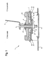
- Fig. 1 is a sectional view of a first embodiment of the device 1 according to the invention is shown, in which the screw 5 in the region of its screw head with the window regulator guide rail 2 by means of an epoxy resin is rotatably and non-displaceably connected. A movement of the screw 5 in the indicated z-direction will thus be carried out completely by the window regulator guide rail 2.
- the screw 5 extends through the upper locking element 6 and the lower locking element 7 therethrough.
- An adjustment of the upper locking element 6 in the z-direction is effected by the screw engagement of the screw 5 with a rivet nut 4, the female part 17 has an internal thread.
- the adjustment of the lower element 7 is again via the screw engagement of the nut 8 with the screw 5, wherein between the lower part 7 of the locking element 6, 7 and the nut 8, a washer 37 is arranged, whose size is a transmission of the displacement of the nut 8 along the screw 5 on the lower part 7 of the locking element 6, 7 allows.
- the entire latching element 6, 7 rests on a sheet holder 18 and is detachably connected thereto via clip connections, in which locking lugs 23, 24 are introduced into the sheet holder 18 holes are bent during the insertion process and after passing the locking lugs 23, 24 spring back to their original position.
- the power transmission of the nut 8 on the locking element 6, 7 takes place indirectly via a arranged between the blank holder 18 and the nut 8 washer.
- the locking lugs 23, 24 provided for the connection of the latching element 6, 7 with the sheet metal holder 18 serve alternatively for connecting the entire device 1 to the inner door panel 13.
- the upper element 6 and the lower element 7 has been set in advance in the y direction.
- a fixation of the upper element 6 with the lower element 7 in the set relative position takes place not only on the screw 5, but rather on the engagement of the corresponding teeth 35, 36 on the opposite sides of the upper element 6 and the lower element. 7 Slipping out of this locking position is further prevented by means of a plurality of spring elements 16, which form an integral part of the lower element 7 in the illustrated embodiment, completely encompass the upper element 6 and apply a force to the upper element 6 in the direction of the lower element 7.
- FIG. 2 shows a second preferred embodiment of a device 1 according to the invention, in which in particular the shape of the lower element 7, the upper element 6 and the sheet metal holder 18 deviates from the first embodiment shown in FIG.
- An adjustment of the upper element 7 also takes place in this case via a rotatable threaded nut 4, in which the screw 5 engages.
- the spring elements 16 are not an integral part of the lower element 7, but are formed as additional components.
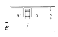
- FIG. 3 shows a schematic plan view of a device 1 according to the invention, which is arranged between the two ribs 22a, 22b both for insertion aid and for preventing rotation.
- the ribs 22a, 22b are in the illustrated variant integral components of a function carrier 21, which in turn is connected to the inner door panel 13.
- a function carrier 21 which in turn is connected to the inner door panel 13.
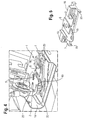
- a third preferred embodiment of the device 1 according to the invention is shown.
- the locking element 6.7 consisting of upper element 6 and lower element 7 is also connected in the illustrated case with the sheet metal holder 18 via latching elements 23.
- the screw 5, which passes through the latching element 6, 7 as well as through the sheet holder 8 and is in screw engagement with (not shown) nuts for adjustment in the z-direction, is non-slidably connected to a foot portion of the window regulator guide rail 2.
- a cable pull roller 25 for the window regulator mechanism is connected to the window regulator guide rail 2.
- a screw 20 In order to prevent the window regulator guide rail 2 from rotating during adjustment in the z-direction about the pivot point of the screw 5, an additional screw point is provided in which a screw 20 likewise runs through the foot of the window regulator guide rail 2 and into one Bore on a lateral projection 19 of the upper element 6 engages.
- the locking element 6, 7 of the third embodiment shown in Fig. 4 is shown in the non-installed state. It can be seen that the lower element 7 is formed substantially symmetrically, with the locking lugs 23 shown on the right side in FIG. 5 also being found on the left side of the figure. The same applies to the spring elements 16.
- the upper element 6, however, is formed asymmetrically, wherein the bore for the (not shown) screw which is to extend through the projection 19, both laterally and in the longitudinal direction of the locking element 6, 7 offset from the Bore for the (not shown) adjusting screw is arranged.
- Fig. 6 is a cross-sectional view of a sliding sliding member 26, the parapet plate 27 and the window regulator guide rail 2 together at the top Attach attachment point for the adjustable in the manner of the invention window regulator guide rail 2, shown.
- the sliding element 26 has two pairs of parallel aligned receptacles into which edge regions of the parapet plate 27 and the window regulator guide rail 2 can engage. Laterally arranged spring elements 28a, 28b thereby cause a tension of sliding element 26 and parapet plate 27th
- FIG. 7 shows a perspective view of the sliding element 26 shown in FIG.
- the sliding element 26 has, in addition to the spring elements 28a, 28b, in addition a Ausrastsch 29, the distal end has a projection which protrudes from the plane defined by the receptacles for the (not shown) parapet plate plane.
- FIG. 8 shows a schematic perspective view of a part of the parapet plate 27 in the region of the upper attachment point.
- the parapet plate 27 has a substantially T-shaped opening whose upper, essentially horizontal leg has a width which makes it possible to insert the sliding element (not shown) in the width direction.
- the distance between the lower leg of the opening 30 delimiting balustrade edges is selected so that it corresponds to the width of the (not shown) sliding member and the receptacles arranged therein for the parapet plate 27 so that a sliding along the sliding member (not shown) along the vertical leg of the opening 30 is made possible.
- the length and the arrangement of the safety device 29 shown in FIG. 7 are selected such that it is not possible to pass the sliding element 26 from the vertical part of the opening 30 to its horizontal part without bending the safety device 29 ,
- FIG. 9 shows, in a schematic perspective view, the upper part of the window lifter guide rail 2, which is to be attached to the sill plate 27 shown in FIG. 8 by means of the sliding element 26 shown in FIGS. 6 and 7.
- the window lifter guide rail 2 has for this purpose an opening 31 which is designed so that the slider 26 shown in Figures 6 and 7 can be inserted rotated in the longitudinal direction of the guide rail 2 and is then rotated by 90 ° clockwise that the the opening 31 surrounding edge portions of the guide rail 2 engage in the provided on the slider 26 shots.
- the guide rail 2 also has, in the vicinity of the attachment point, a further deflection roller 33 for the schematically indicated cable pull 34 for the window regulator mechanism (not shown).
- FIG. 10 shows an alternative embodiment of the window lifter guide rail 2 (not shown here) with the sill plate 27 shown as an indication.
- the sliding element 26 has a substantially cylindrical shape whose diameter is smaller than that of the introduction region 38a of the opening in the parapet plate 27, but greater than the distance of adjacent edge regions of the parapet plate 27 along the displacement path for the sliding element 26 in the parapet plate 27.
Landscapes
- Window Of Vehicle (AREA)
- Power-Operated Mechanisms For Wings (AREA)
Applications Claiming Priority (1)
| Application Number | Priority Date | Filing Date | Title |
|---|---|---|---|
| DE102006012176A DE102006012176A1 (de) | 2006-03-16 | 2006-03-16 | Einstellbarer Fensterheber I |
Publications (2)
| Publication Number | Publication Date |
|---|---|
| EP1835113A2 true EP1835113A2 (fr) | 2007-09-19 |
| EP1835113A3 EP1835113A3 (fr) | 2012-06-27 |
Family
ID=38066490
Family Applications (1)
| Application Number | Title | Priority Date | Filing Date |
|---|---|---|---|
| EP07005039A Withdrawn EP1835113A3 (fr) | 2006-03-16 | 2007-03-12 | Lève-glace réglable |
Country Status (3)
| Country | Link |
|---|---|
| US (1) | US8069610B2 (fr) |
| EP (1) | EP1835113A3 (fr) |
| DE (1) | DE102006012176A1 (fr) |
Families Citing this family (26)
| Publication number | Priority date | Publication date | Assignee | Title |
|---|---|---|---|---|
| US7640697B2 (en) * | 2002-10-30 | 2010-01-05 | Brose Fahrzeugteile Gmbh & Co. Kg, Coburg | Device for connecting the fixing region of a guide rail to the door body of a vehicle door |
| DE102005008080A1 (de) * | 2005-02-22 | 2006-08-24 | Arvinmeritor Gmbh | Fensterheberschiene, Baugruppe bestehend aus Fensterheberschiene und Montagelasche, sowie Montageverfahren |
| DE102005033115A1 (de) * | 2005-07-11 | 2007-01-25 | Brose Fahrzeugteile Gmbh & Co. Kommanditgesellschaft, Coburg | Aggregateträger für eine Kraftfahrzeugtür |
| EP2132054B1 (fr) * | 2007-03-13 | 2018-12-26 | Inteva Products, LLC. | Rail de régulateur de câble et dispositif de transport avec poulie emboîtable |
| ES2387251T3 (es) * | 2008-02-21 | 2012-09-19 | Fiat Group Automobiles S.P.A. | Conjunto de soporte de vidrio para una puerta de vehículo a motor con un borde superior sin armazón |
| BRPI1013251A2 (pt) * | 2009-03-10 | 2016-04-05 | Brose Fahrzeugteile | "módulo de porta para montagem em uma porta de veículo." |
| WO2010135445A2 (fr) * | 2009-05-19 | 2010-11-25 | Inteva Products Llc. | Système de lève-glaces à commande par câble à double voie |
| WO2010135448A2 (fr) * | 2009-05-19 | 2010-11-25 | Inteva Products Llc. | Ensemble lève-glaces à commande par câble à voie unique |
| WO2010135443A2 (fr) * | 2009-05-19 | 2010-11-25 | Inteva Products Llc. | Procédé de fixation pour système lève-vitre |
| JP5589482B2 (ja) * | 2010-03-25 | 2014-09-17 | アイシン精機株式会社 | 車両用ウインドレギュレータ装置 |
| DE202010009865U1 (de) * | 2010-07-05 | 2011-10-27 | Brose Fahrzeugteile Gmbh & Co. Kg, Hallstadt | Vorrichtung zum Einstellen und Arretieren der Lage einer Führungsschiene für eine verstellbare Fensterscheibe in einer Fahrzeugtür |
| US8528259B1 (en) * | 2012-07-18 | 2013-09-10 | Ford Global Technologies, Llc | Method of adjusting door glass cross car for frameless window systems |
| US9481231B2 (en) | 2013-07-10 | 2016-11-01 | GM Global Technology Operations LLC | Automotive glass channel bracket and method |
| JP6344085B2 (ja) * | 2014-06-23 | 2018-06-20 | アイシン精機株式会社 | 昇降装置及びその昇降装置を備える車両用ドア |
| JP6374296B2 (ja) * | 2014-10-31 | 2018-08-15 | 株式会社ハイレックスコーポレーション | ガイドレール嵌合構造及びウィンドウレギュレータ |
| JP6723826B2 (ja) * | 2016-05-24 | 2020-07-15 | シロキ工業株式会社 | ワイヤ式ウインドレギュレータ |
| US20190078366A1 (en) * | 2017-09-08 | 2019-03-14 | Magna Closures Inc. | Light weight two piece frameless door module with adjustment features |
| KR20190028084A (ko) * | 2017-09-08 | 2019-03-18 | 현대자동차주식회사 | 비모듈형 듀얼 레귤레이터 어셈블리 |
| KR102575156B1 (ko) * | 2018-10-15 | 2023-09-06 | 현대자동차주식회사 | 위치조정이 가능한 도어 글래스 |
| US11319742B2 (en) * | 2018-10-18 | 2022-05-03 | Magna Closures Inc. | Door module with frameless glass configuration having adjustable glass run channels |
| DE102019215093B3 (de) * | 2019-10-01 | 2021-03-18 | Brose Fahrzeugteile Se & Co. Kommanditgesellschaft, Bamberg | Befestigungsvorrichtung für einen Fensterheber sowie Fensterheber |
| US11851926B1 (en) | 2021-09-23 | 2023-12-26 | Apple Inc. | Panel with pivoting and translational motion |
| DE102021211902A1 (de) * | 2021-10-21 | 2023-04-27 | Brose Fahrzeugteile Se & Co. Kommanditgesellschaft, Bamberg | Befestigungsvorrichtung für einen Fensterheber sowie Fensterheber |
| DE102023101158A1 (de) | 2022-02-09 | 2023-08-10 | Magna Closures Inc. | Verstellbare hebeplatte und fensterheberschienen für türscheiben und zugehörige verfahren |
| US12168902B1 (en) | 2022-06-07 | 2024-12-17 | Apple Inc. | Window |
| US12241300B1 (en) * | 2023-08-28 | 2025-03-04 | Shigeki Arimoto | Frameless door window regulator adjustment assembly |
Family Cites Families (14)
| Publication number | Priority date | Publication date | Assignee | Title |
|---|---|---|---|---|
| US3844064A (en) * | 1971-02-05 | 1974-10-29 | Nissan Motor | Guiding mechanism for sliding windows of automotive vehicles |
| US4586290A (en) * | 1985-03-25 | 1986-05-06 | General Motors Corporation | Telescoping window stabilizing mechanism |
| US4869123A (en) * | 1985-11-18 | 1989-09-26 | Ford Motor Company | Cable length self-locking adjustment device |
| DE3613978C1 (de) * | 1986-04-25 | 1987-09-10 | Audi Ag | Kraftfahrzeugtuer |
| DE4435008A1 (de) * | 1994-09-30 | 1996-04-04 | Porsche Ag | Einstellvorrichtung für eine mit einer Fensterheberanordnung zusammenwirkende, rahmenlos ausgebildete Türfensterscheibe eines Kraftfahrzeuges |
| DE19611074A1 (de) * | 1996-03-21 | 1997-09-25 | Brose Fahrzeugteile | Vorrichtung und Verfahren zum Einstellen einer von einem doppelsträngigen Seilfensterheber bewegten rahmenlosen Fensterscheibe durch eine Kippbewegung quer zur Längsachse des Kraftfahrzeugs |
| DE10014946B4 (de) * | 2000-03-21 | 2011-07-21 | Brose Fahrzeugteile GmbH & Co. Kommanditgesellschaft, Coburg, 96450 | Einrichtung zur Einstellung der Lage einer Führungsschiene für eine verstellbare Fensterscheibe eines Kraftfahrzeugs |
| US6425208B1 (en) * | 2000-08-30 | 2002-07-30 | Daimlerchrysler Corporation | Vehicle window track adjustments in the vertical and transverse direction |
| DE10138586B4 (de) * | 2001-08-06 | 2009-04-23 | Brose Fahrzeugteile Gmbh & Co. Kommanditgesellschaft, Coburg | Führungsanordnung für einen Kraftfahrzeugfensterheber |
| DE10145180B4 (de) * | 2001-09-07 | 2005-07-21 | Brose Fahrzeugteile Gmbh & Co. Kg, Coburg | Einstellbarer Mitnehmer zur Anbindung einer Fensterscheibe an einen Kraftfahrzeugfensterheber |
| FR2834673B1 (fr) * | 2002-01-11 | 2004-10-15 | Meritor Light Vehicle Sys Ltd | Portiere a rail de guidage reglable et procede d'assemblage correspondant |
| US7640697B2 (en) * | 2002-10-30 | 2010-01-05 | Brose Fahrzeugteile Gmbh & Co. Kg, Coburg | Device for connecting the fixing region of a guide rail to the door body of a vehicle door |
| DE20219264U1 (de) * | 2002-12-06 | 2003-02-27 | Brose Fahrzeugteile GmbH & Co. KG, Coburg, 96450 Coburg | Vorrichtung zum Verbinden des Befestigungsbereichs einer Führungsschiene mit dem Türboden einer Fahrzeugtür |
| US7467494B2 (en) * | 2003-09-15 | 2008-12-23 | Intier Automotive Closures Inc. | Vehicle window adjustment device |
-
2006
- 2006-03-16 DE DE102006012176A patent/DE102006012176A1/de not_active Withdrawn
-
2007
- 2007-03-12 EP EP07005039A patent/EP1835113A3/fr not_active Withdrawn
- 2007-03-16 US US11/725,150 patent/US8069610B2/en not_active Expired - Fee Related
Non-Patent Citations (1)
| Title |
|---|
| None |
Also Published As
| Publication number | Publication date |
|---|---|
| DE102006012176A1 (de) | 2007-09-20 |
| US8069610B2 (en) | 2011-12-06 |
| EP1835113A3 (fr) | 2012-06-27 |
| US20070214726A1 (en) | 2007-09-20 |
Similar Documents
| Publication | Publication Date | Title |
|---|---|---|
| DE102006012176A1 (de) | Einstellbarer Fensterheber I | |
| DE60123691T2 (de) | Zusammenbau einer Türplatte | |
| DE102018121746A1 (de) | Leichtgewichtiges zweistückiges rahmenloses Türmodul mit Einstellmerkmalen | |
| DE19956756C2 (de) | Einstellbarer Mitnehmer für einen Fensterheber einer rahmenlosen Fahrzeugtür | |
| EP1904323B1 (fr) | Support d'organe pour portiere de vehicule a moteur | |
| DE20214668U1 (de) | Mitnehmer für einen Kraftfahrzeugfensterheber | |
| DE102009011120B4 (de) | Einstelleinrichtung für die Fensterscheibe eines Fensterhebers | |
| DE10204610A1 (de) | Fensterheber für eine Kraftfahrzeugtür | |
| DE102005021585A1 (de) | Gleitstück für einen Fensterheber und damit ausgestatteter Fahrzeugfensterheber | |
| DE69408612T2 (de) | Antriebs- und Arretiervorrichtung für Kraftfahrzeugfenster | |
| EP1212206A1 (fr) | Module de porte a fixer sur un corps de porte constituant une partie de base de porte d'un vehicule automobile, et procede de montage d'un tel module de porte | |
| DE202005017112U1 (de) | Türbaugruppe für eine Kraftfahrzeugtür | |
| DE102018105959B4 (de) | Montageanordnung eines Luftleitelements | |
| DE4124528C1 (en) | Solid car roof with sun roof aperture - has threaded adjuster with two parts, effective in opposite directions via link | |
| DE102007014098A1 (de) | Bahngesteuerter Kraftfahrzeug-Fensterheber | |
| DE4316651A1 (de) | Vorrichtung zum Verbinden eines Mitnehmers eines Fensterhebers mit einer Fensterscheibe | |
| EP1400649A2 (fr) | Elément d'entraínement pour un lève-vitre de véhicule | |
| DE202015104588U1 (de) | Fensterheberbaugruppe für ein Kraftfahrzeug | |
| DE202011051890U1 (de) | Fensterheber für Kraftfahrzeuge | |
| EP1400650B1 (fr) | Elément d'entraînement pour un lève-vitre de véhicule | |
| DE102004043000A1 (de) | Fahrzeugtür | |
| DE102010063562A1 (de) | Fensterheber | |
| DE19717806A1 (de) | Mitnehmer für einen Seilzugfensterheber | |
| DE102008005744B3 (de) | Befestigungseinrichtung für Fensterhebermodule | |
| DE202008014752U1 (de) | Fensterheberbaugruppe |
Legal Events
| Date | Code | Title | Description |
|---|---|---|---|
| PUAI | Public reference made under article 153(3) epc to a published international application that has entered the european phase |
Free format text: ORIGINAL CODE: 0009012 |
|
| AK | Designated contracting states |
Kind code of ref document: A2 Designated state(s): AT BE BG CH CY CZ DE DK EE ES FI FR GB GR HU IE IS IT LI LT LU LV MC MT NL PL PT RO SE SI SK TR |
|
| AX | Request for extension of the european patent |
Extension state: AL BA HR MK YU |
|
| PUAL | Search report despatched |
Free format text: ORIGINAL CODE: 0009013 |
|
| AK | Designated contracting states |
Kind code of ref document: A3 Designated state(s): AT BE BG CH CY CZ DE DK EE ES FI FR GB GR HU IE IS IT LI LT LU LV MC MT NL PL PT RO SE SI SK TR |
|
| AX | Request for extension of the european patent |
Extension state: AL BA HR MK RS |
|
| RIC1 | Information provided on ipc code assigned before grant |
Ipc: E05F 11/48 20060101ALI20120524BHEP Ipc: E05F 11/38 20060101AFI20120524BHEP |
|
| 17P | Request for examination filed |
Effective date: 20121212 |
|
| 17Q | First examination report despatched |
Effective date: 20130207 |
|
| AKX | Designation fees paid |
Designated state(s): AT BE BG CH CY CZ DE DK EE ES FI FR GB GR HU IE IS IT LI LT LU LV MC MT NL PL PT RO SE SI SK TR |
|
| STAA | Information on the status of an ep patent application or granted ep patent |
Free format text: STATUS: THE APPLICATION IS DEEMED TO BE WITHDRAWN |
|
| 18D | Application deemed to be withdrawn |
Effective date: 20151001 |