EP1835154B1 - Elektronische Steuerung, System für vergasergetriebene Verbrennungsmotoren mit Kontrolle des Zündzeitpunktes - Google Patents
Elektronische Steuerung, System für vergasergetriebene Verbrennungsmotoren mit Kontrolle des Zündzeitpunktes Download PDFInfo
- Publication number
- EP1835154B1 EP1835154B1 EP07103813.7A EP07103813A EP1835154B1 EP 1835154 B1 EP1835154 B1 EP 1835154B1 EP 07103813 A EP07103813 A EP 07103813A EP 1835154 B1 EP1835154 B1 EP 1835154B1
- Authority
- EP
- European Patent Office
- Prior art keywords
- engine
- control
- mapping
- carburettor
- mappings
- Prior art date
- Legal status (The legal status is an assumption and is not a legal conclusion. Google has not performed a legal analysis and makes no representation as to the accuracy of the status listed.)
- Ceased
Links
- 238000002485 combustion reaction Methods 0.000 title claims description 10
- 238000013507 mapping Methods 0.000 claims description 48
- 238000012937 correction Methods 0.000 claims description 20
- 239000000446 fuel Substances 0.000 claims description 17
- 238000011217 control strategy Methods 0.000 claims description 11
- 239000000203 mixture Substances 0.000 claims description 11
- 238000010438 heat treatment Methods 0.000 claims description 7
- 239000007858 starting material Substances 0.000 claims description 7
- 239000000839 emulsion Substances 0.000 claims description 5
- 230000007613 environmental effect Effects 0.000 claims description 5
- 238000000034 method Methods 0.000 claims description 4
- 238000001514 detection method Methods 0.000 claims description 3
- 238000010586 diagram Methods 0.000 description 14
- 239000003921 oil Substances 0.000 description 12
- 230000001133 acceleration Effects 0.000 description 6
- 239000007789 gas Substances 0.000 description 6
- 238000005461 lubrication Methods 0.000 description 5
- 230000004913 activation Effects 0.000 description 4
- 230000008901 benefit Effects 0.000 description 4
- 230000003197 catalytic effect Effects 0.000 description 4
- 230000015572 biosynthetic process Effects 0.000 description 3
- 238000012545 processing Methods 0.000 description 3
- 239000000523 sample Substances 0.000 description 3
- 230000001052 transient effect Effects 0.000 description 3
- 238000010276 construction Methods 0.000 description 2
- 230000006872 improvement Effects 0.000 description 2
- 238000002347 injection Methods 0.000 description 2
- 239000007924 injection Substances 0.000 description 2
- 230000009467 reduction Effects 0.000 description 2
- 239000000243 solution Substances 0.000 description 2
- 101150046852 Map10 gene Proteins 0.000 description 1
- 101150085390 RPM1 gene Proteins 0.000 description 1
- 238000010521 absorption reaction Methods 0.000 description 1
- 230000002411 adverse Effects 0.000 description 1
- 238000004458 analytical method Methods 0.000 description 1
- QVGXLLKOCUKJST-UHFFFAOYSA-N atomic oxygen Chemical compound [O] QVGXLLKOCUKJST-UHFFFAOYSA-N 0.000 description 1
- 238000006243 chemical reaction Methods 0.000 description 1
- 230000010485 coping Effects 0.000 description 1
- 125000004122 cyclic group Chemical group 0.000 description 1
- 238000003745 diagnosis Methods 0.000 description 1
- 230000000694 effects Effects 0.000 description 1
- 239000003344 environmental pollutant Substances 0.000 description 1
- 230000007717 exclusion Effects 0.000 description 1
- 238000009313 farming Methods 0.000 description 1
- 238000010413 gardening Methods 0.000 description 1
- 230000005484 gravity Effects 0.000 description 1
- 229930195733 hydrocarbon Natural products 0.000 description 1
- 150000002430 hydrocarbons Chemical class 0.000 description 1
- 230000002706 hydrostatic effect Effects 0.000 description 1
- 230000001939 inductive effect Effects 0.000 description 1
- 238000009434 installation Methods 0.000 description 1
- 239000000314 lubricant Substances 0.000 description 1
- 239000010687 lubricating oil Substances 0.000 description 1
- 238000012423 maintenance Methods 0.000 description 1
- 238000012986 modification Methods 0.000 description 1
- 230000004048 modification Effects 0.000 description 1
- 239000001301 oxygen Substances 0.000 description 1
- 229910052760 oxygen Inorganic materials 0.000 description 1
- 239000002245 particle Substances 0.000 description 1
- 231100000719 pollutant Toxicity 0.000 description 1
- 238000002360 preparation method Methods 0.000 description 1
- 230000006641 stabilisation Effects 0.000 description 1
- 239000000126 substance Substances 0.000 description 1
- 230000001360 synchronised effect Effects 0.000 description 1
- 230000001131 transforming effect Effects 0.000 description 1
Images



Classifications
-
- F—MECHANICAL ENGINEERING; LIGHTING; HEATING; WEAPONS; BLASTING
- F02—COMBUSTION ENGINES; HOT-GAS OR COMBUSTION-PRODUCT ENGINE PLANTS
- F02P—IGNITION, OTHER THAN COMPRESSION IGNITION, FOR INTERNAL-COMBUSTION ENGINES; TESTING OF IGNITION TIMING IN COMPRESSION-IGNITION ENGINES
- F02P5/00—Advancing or retarding ignition; Control therefor
- F02P5/04—Advancing or retarding ignition; Control therefor automatically, as a function of the working conditions of the engine or vehicle or of the atmospheric conditions
- F02P5/145—Advancing or retarding ignition; Control therefor automatically, as a function of the working conditions of the engine or vehicle or of the atmospheric conditions using electrical means
- F02P5/15—Digital data processing
- F02P5/1502—Digital data processing using one central computing unit
- F02P5/1504—Digital data processing using one central computing unit with particular means during a transient phase, e.g. acceleration, deceleration, gear change
-
- F—MECHANICAL ENGINEERING; LIGHTING; HEATING; WEAPONS; BLASTING
- F02—COMBUSTION ENGINES; HOT-GAS OR COMBUSTION-PRODUCT ENGINE PLANTS
- F02D—CONTROLLING COMBUSTION ENGINES
- F02D3/00—Controlling low-pressure fuel injection, i.e. where the fuel-air mixture containing fuel thus injected will be substantially compressed by the compression stroke of the engine, by means other than controlling only an injection pump
- F02D3/04—Controlling fuel-injection and carburation, e.g. of alternative systems
-
- F—MECHANICAL ENGINEERING; LIGHTING; HEATING; WEAPONS; BLASTING
- F02—COMBUSTION ENGINES; HOT-GAS OR COMBUSTION-PRODUCT ENGINE PLANTS
- F02D—CONTROLLING COMBUSTION ENGINES
- F02D37/00—Non-electrical conjoint control of two or more functions of engines, not otherwise provided for
- F02D37/02—Non-electrical conjoint control of two or more functions of engines, not otherwise provided for one of the functions being ignition
-
- F—MECHANICAL ENGINEERING; LIGHTING; HEATING; WEAPONS; BLASTING
- F02—COMBUSTION ENGINES; HOT-GAS OR COMBUSTION-PRODUCT ENGINE PLANTS
- F02D—CONTROLLING COMBUSTION ENGINES
- F02D41/00—Electrical control of supply of combustible mixture or its constituents
- F02D41/02—Circuit arrangements for generating control signals
- F02D41/021—Introducing corrections for particular conditions exterior to the engine
- F02D41/0215—Introducing corrections for particular conditions exterior to the engine in relation with elements of the transmission
- F02D41/0225—Introducing corrections for particular conditions exterior to the engine in relation with elements of the transmission in relation with the gear ratio or shift lever position
-
- F—MECHANICAL ENGINEERING; LIGHTING; HEATING; WEAPONS; BLASTING
- F02—COMBUSTION ENGINES; HOT-GAS OR COMBUSTION-PRODUCT ENGINE PLANTS
- F02P—IGNITION, OTHER THAN COMPRESSION IGNITION, FOR INTERNAL-COMBUSTION ENGINES; TESTING OF IGNITION TIMING IN COMPRESSION-IGNITION ENGINES
- F02P5/00—Advancing or retarding ignition; Control therefor
- F02P5/04—Advancing or retarding ignition; Control therefor automatically, as a function of the working conditions of the engine or vehicle or of the atmospheric conditions
- F02P5/045—Advancing or retarding ignition; Control therefor automatically, as a function of the working conditions of the engine or vehicle or of the atmospheric conditions combined with electronic control of other engine functions, e.g. fuel injection
-
- F—MECHANICAL ENGINEERING; LIGHTING; HEATING; WEAPONS; BLASTING
- F02—COMBUSTION ENGINES; HOT-GAS OR COMBUSTION-PRODUCT ENGINE PLANTS
- F02P—IGNITION, OTHER THAN COMPRESSION IGNITION, FOR INTERNAL-COMBUSTION ENGINES; TESTING OF IGNITION TIMING IN COMPRESSION-IGNITION ENGINES
- F02P5/00—Advancing or retarding ignition; Control therefor
- F02P5/04—Advancing or retarding ignition; Control therefor automatically, as a function of the working conditions of the engine or vehicle or of the atmospheric conditions
- F02P5/145—Advancing or retarding ignition; Control therefor automatically, as a function of the working conditions of the engine or vehicle or of the atmospheric conditions using electrical means
- F02P5/15—Digital data processing
- F02P5/1502—Digital data processing using one central computing unit
- F02P5/1506—Digital data processing using one central computing unit with particular means during starting
-
- F—MECHANICAL ENGINEERING; LIGHTING; HEATING; WEAPONS; BLASTING
- F02—COMBUSTION ENGINES; HOT-GAS OR COMBUSTION-PRODUCT ENGINE PLANTS
- F02D—CONTROLLING COMBUSTION ENGINES
- F02D11/00—Arrangements for, or adaptations to, non-automatic engine control initiation means, e.g. operator initiated
- F02D11/06—Arrangements for, or adaptations to, non-automatic engine control initiation means, e.g. operator initiated characterised by non-mechanical control linkages, e.g. fluid control linkages or by control linkages with power drive or assistance
- F02D11/10—Arrangements for, or adaptations to, non-automatic engine control initiation means, e.g. operator initiated characterised by non-mechanical control linkages, e.g. fluid control linkages or by control linkages with power drive or assistance of the electric type
- F02D2011/101—Arrangements for, or adaptations to, non-automatic engine control initiation means, e.g. operator initiated characterised by non-mechanical control linkages, e.g. fluid control linkages or by control linkages with power drive or assistance of the electric type characterised by the means for actuating the throttles
- F02D2011/102—Arrangements for, or adaptations to, non-automatic engine control initiation means, e.g. operator initiated characterised by non-mechanical control linkages, e.g. fluid control linkages or by control linkages with power drive or assistance of the electric type characterised by the means for actuating the throttles at least one throttle being moved only by an electric actuator
-
- F—MECHANICAL ENGINEERING; LIGHTING; HEATING; WEAPONS; BLASTING
- F02—COMBUSTION ENGINES; HOT-GAS OR COMBUSTION-PRODUCT ENGINE PLANTS
- F02D—CONTROLLING COMBUSTION ENGINES
- F02D2400/00—Control systems adapted for specific engine types; Special features of engine control systems not otherwise provided for; Power supply, connectors or cabling for engine control systems
- F02D2400/04—Two-stroke combustion engines with electronic control
-
- F—MECHANICAL ENGINEERING; LIGHTING; HEATING; WEAPONS; BLASTING
- F02—COMBUSTION ENGINES; HOT-GAS OR COMBUSTION-PRODUCT ENGINE PLANTS
- F02D—CONTROLLING COMBUSTION ENGINES
- F02D35/00—Controlling engines, dependent on conditions exterior or interior to engines, not otherwise provided for
- F02D35/0015—Controlling engines, dependent on conditions exterior or interior to engines, not otherwise provided for using exhaust gas sensors
- F02D35/0023—Controlling air supply
- F02D35/003—Controlling air supply by means of by-pass passages
-
- F—MECHANICAL ENGINEERING; LIGHTING; HEATING; WEAPONS; BLASTING
- F02—COMBUSTION ENGINES; HOT-GAS OR COMBUSTION-PRODUCT ENGINE PLANTS
- F02D—CONTROLLING COMBUSTION ENGINES
- F02D41/00—Electrical control of supply of combustible mixture or its constituents
- F02D41/02—Circuit arrangements for generating control signals
- F02D41/021—Introducing corrections for particular conditions exterior to the engine
- F02D41/0235—Introducing corrections for particular conditions exterior to the engine in relation with the state of the exhaust gas treating apparatus
- F02D41/024—Introducing corrections for particular conditions exterior to the engine in relation with the state of the exhaust gas treating apparatus to increase temperature of the exhaust gas treating apparatus
- F02D41/0245—Introducing corrections for particular conditions exterior to the engine in relation with the state of the exhaust gas treating apparatus to increase temperature of the exhaust gas treating apparatus by increasing temperature of the exhaust gas leaving the engine
-
- F—MECHANICAL ENGINEERING; LIGHTING; HEATING; WEAPONS; BLASTING
- F02—COMBUSTION ENGINES; HOT-GAS OR COMBUSTION-PRODUCT ENGINE PLANTS
- F02D—CONTROLLING COMBUSTION ENGINES
- F02D41/00—Electrical control of supply of combustible mixture or its constituents
- F02D41/02—Circuit arrangements for generating control signals
- F02D41/04—Introducing corrections for particular operating conditions
- F02D41/06—Introducing corrections for particular operating conditions for engine starting or warming up
- F02D41/062—Introducing corrections for particular operating conditions for engine starting or warming up for starting
- F02D41/064—Introducing corrections for particular operating conditions for engine starting or warming up for starting at cold start
-
- Y—GENERAL TAGGING OF NEW TECHNOLOGICAL DEVELOPMENTS; GENERAL TAGGING OF CROSS-SECTIONAL TECHNOLOGIES SPANNING OVER SEVERAL SECTIONS OF THE IPC; TECHNICAL SUBJECTS COVERED BY FORMER USPC CROSS-REFERENCE ART COLLECTIONS [XRACs] AND DIGESTS
- Y02—TECHNOLOGIES OR APPLICATIONS FOR MITIGATION OR ADAPTATION AGAINST CLIMATE CHANGE
- Y02T—CLIMATE CHANGE MITIGATION TECHNOLOGIES RELATED TO TRANSPORTATION
- Y02T10/00—Road transport of goods or passengers
- Y02T10/10—Internal combustion engine [ICE] based vehicles
- Y02T10/40—Engine management systems
Definitions
- the present invention concerns an electronic control system for the preparation, dosing and ignition of the air-fuel mixture in internal-combustion engines.
- it concerns such a system for carburettor-powered, controlled-ignition, internal-combustion engines.
- These units by reading and analysing a certain number of operation parameters, are arranged to adjust in an optimised manner the drive of a series of actuation devices which establish the dosing of the fuel mixture and combustion conditions.
- an oxygen sensor (the so-called lambda probe) introduced in the exhaust system has also been used, which analyses exhaust gases and supplies the electronic control unit with a series of detected values, which allows the same unit to assess the operation conditions of the engine and to perform correction operations on the carburettor, so as to bring the quality of exhaust gases back to the desired values.
- lambda probe the so-called lambda probe
- the electronic injection systems commonly mounted on motor vehicles - which would allow to partly improve the aspects set forth above - are not suited to the use on small engines, due to the complexity of such systems, to the cost, to the bulk, to the power consumption and to the investments required to customise existing small engines.
- commonly-used electronic injection systems need a fuel supply pump which has a certain bulk, cost and power consumption which are not sustainable in small, controlled-ignition engines, such as scooters, light motorbikes, off-road motorbikes, low-powered motorbikes, outboard engines, gardening and farming equipment, motor generators and more.
- control system for combustion engine which combine the control of the fuel mixture and the ignition timing, are shown in EP1277939A2 , US5031593A , US4446832A and US6298824B1 .
- the scope of the present invention is hence that of providing a combustion control system for controlled-ignition engines, which overcomes the mentioned drawbacks and which is simpler and easier to control, hence cheaper both in terms of construction and of power, as well as being suited to reduce to a minimum polluting emissions.
- the objects which the Applicant has set itself in order to achieve the above-mentioned results are of
- the control of the ignition spark advance and of the air/fuel ratio is carried out according to a basic mapping, which is a function of signals representing the position of the engine shaft over time, and with a correction mapping which is a function of the temperature at least in correspondence of the engine.
- a basic mapping which is a function of signals representing the position of the engine shaft over time
- a correction mapping which is a function of the temperature at least in correspondence of the engine.
- Such correction mappings establish special control strategies, which correct the effect of the temperature (both the engine local one, and the environmental temperature) and optimise transient operation (start, vehicle accelerations/decelerations, gas control, turning off, ...), to the advantage of driveability in any condition.
- control strategies which may be implemented with the system of the invention provide to establish mappings of the main operation parameters (air/fuel mixture, ignition spark advance and also oil pump) both in normal operation and in start-up conditions.
- the operation of the control unit is further based on signals also coming from a vehicle speed sensor and from an engine shaft position sensor (capable of deriving also the rotation speed).
- control strategy is implemented also based on the signals coming from a position sensor of the air valve and of the carburettor throttle (if any), of a valve of the engine outlet port, of a reduction valve of the exhaust pipe and other.
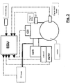
- a control system of a carburettor vehicle substantially comprises a central electronic control unit - equipped with a logic unit wherein control strategies are implemented (through a suitable software and/or firmware) - a series of sensors for the detection of the fundamental operation parameters and a series of actuators which are diagrammatically clearly identified in the drawing.
- fig. 2 shows five sensors, known per se, which detect the number of revolutions of the engine shaft, the room temperature, the engine temperature, the ignition contact, and the battery voltage, respectively.
- the devices which pick up the outgoing signals from the engine control unit, transforming them into indications for the user or controls for actuating devices: for example the carburettor or throttle body, the oil pump for the fuel mixture, the ignition for the spark plugs, the engine condition warning lights, the engine revolution counter and temperature thermometers.
- the relative arrangement of the various devices and sensors is diagrammatically exemplified in fig. 3 .
- the room temperature sensor is preferably integrated in the electronic control unit.
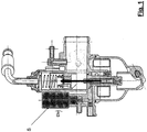
- a carburettor (known per se) which may be controlled electronically is exemplarily illustrated also in fig. 1 .
- this carburettor has one or more solenoid actuators for controlling the A/F (air/fuel) ratio of the mixture, acting on the additional (emulsion) air circuit in addition to the main (emulsion) air and on a secondary air circuit (bypass).
- the solenoid actuator S acting on the secondary air flow can be identified.
- the carburettor is further provided with an electric starter device, for controlling the A/F ratio during the start-up phases, whose peculiarities will be described further on.
- the system controls in an integrated way also an electric oil pump, itself provided with a solenoid actuator, suitable for fine tuning the amount of oil supplied to the fuel mixture for engine lubrication.
- the system is preferably equipped with variable-advance and controllable-advance capacitive discharge ignition (CDI), although also simpler inductive discharge ignitions may also be used.
- CDI variable-advance and controllable-advance capacitive discharge ignition
- the system of the invention is extremely simple and, even forfeiting complex detection devices or actuators, it allows to obtain an excellent adjustment of the operation parameters along the lines set forth in the preliminary remarks.
- the strategy of the invention provides to obtain an integrated control of the main functions, at least of the advance, carburettor (A/F) and oil pump, setting a basic adjustment, according to the information coming from the sensor on the engine shaft (capable of detecting engine position and speed), to which adjustment suitable corrections are added, determined on the basis of values detected at least by the engine temperature and room temperature sensors.
- A/F carburettor
- oil pump setting a basic adjustment, according to the information coming from the sensor on the engine shaft (capable of detecting engine position and speed), to which adjustment suitable corrections are added, determined on the basis of values detected at least by the engine temperature and room temperature sensors.
- control is carried out in an integrated manner, due to the fact that the logical unit is implemented in a single electronic control unit, combining the basic mapping with various corrective mappings or tuning mappings determined according to secondary parameters, such as engine temperature, room temperature, throttle valve position, and so on.
- the ratio between the control of the bypass air valve or of the ignition spark advance to the number of engine revolutions (RPM) is defined.
- the integrated control system acts on the carburettor controlling the bypass valve solenoid through pulse width modulation (PWM) techniques.
- PWM pulse width modulation
- spark advance (adv) controls and carburettor PWM controls are a variable function of RPM, of its time derivative (dRPM/dt), as well as of the engine temperature (Teng) and of the room temperature (Tamb).
- these functions allow to adjust the operation parameters taking into account the desired A/F strategy and the corrections required to compensate for low operation temperatures.
- Such functions are preferably determined by a basic mapping, exclusively connected to the RPM parameter, plus an incremental or correction mapping which takes into account the other three parameters (dRPM/dt; Teng; Tamb).
- the values of the incremental mapping, or function, ⁇ % are preferably recalculated every 10 engine revolutions, at the most, and are programmable.
- the input values of the PWM/adv functions can be set according to discrete steps, for example every 50 rpm for a total of 16 (Map16) breakpoints; between the various points a linear interpolation of the PWM/adv functions may be used.
- the input values of Tamb and Teng to perform the calculation (of the correction mapping) can be considered in discrete steps, without any interpolation being necessary between these discrete values.
- Map10 a maximum of 10 discrete values can be considered (Map10): such values, which may be programmed in the electronic unit according to the application, are the same for the three functions which adjust the spark advance, the bypass air valve and, possibly, the oil pump.
- Fig. 6 diagrammatically shows a functional diagram illustrating this type of control.
- the correction curves ( ⁇ %) of one of the controls in the basic mapping are shown, as a function of secondary parameters, i.e. of the engine temperature, of the room temperature and of the throttle valve position, respectively. For each of the controls found in the basic mapping these correction curves are determined depending on the secondary parameters.
- the engine revolution speed is determined on the basis of the signal coming from a sensor detecting the transit of a reference index integral with the engine shaft.
- the signal suitably filtered to remove noise and interferences, is then processed by the engine control unit in order to determine the engine revolution speed starting from the revolution period.
- the unit also calculates the time derivative of the engine speed (acceleration).
- the engine speed derivative is further used for taking into account the non-stationary, acceleration and deceleration conditions. Should the value of the derivative lie above certain acceleration or deceleration thresholds, a correction of the ignition advance and carburation parameters is imparted, so as to adapt the engine operation parameters to the requirements of the operation in rapidly changing conditions, for which the mapping performed for the stationary operation would be unsuitable. Intervention thresholds for said correction are values which can be programmed according to the application, i.e. which may be set up in the calibration software.
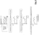
- fig. 8 shows an exemplary diagram, which allows to better understand the application of the correction function to the overcoming of certain acceleration/deceleration thresholds and the linear decay thereof, according to the time or number of revolutions.
- the revolution period detected by the engine control unit can also be used for assessing the cyclic revolution irregularity of the engine and- upon exceeding set irregularity thresholds - implement corrections of the spark advance and carburation in order to reestablish regular engine operation.
- the system can advantageously provide to consider, in the control strategy, not only the signals representing the accelerator or throttle position (TPS), but also the vehicle speed, as will be better highlighted hereinafter.
- TPS accelerator or throttle position
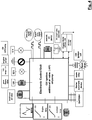
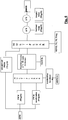
- Fig. 4 shows a functional diagram of an engine control unit devised according to what has been described so far.
- the invention system is capable of brilliantly coping also with transient phases of engine start up, especially cold start up which is particularly critical for the proper activation of the catalyser system and hence for polluting emissions.
- the system also provides to the control of the automatic starter supply (specifically of the heating element contained therein, which can be of any known type, for example a wax one) PWM modulating the supply voltage; using a strategy which prolongs the exclusion times of the automatic starter in the presence of room and/or engine temperatures below preset temperature thresholds (conditions which pose the risk of ice formation in the carburettor ducts), so as to guarantee an optimal drivability also with rigid climates but avoiding polluting emissions and an excessive consumption in normal operation conditions.
- the automatic starter supply specifically of the heating element contained therein, which can be of any known type, for example a wax one
- PWM modulating the supply voltage PWM modulating the supply voltage
- the system provides various adjustable thresholds of room temperature, associated with PWM drive signals having different features.
- the system itself further allows to quickly exclude the starter device if, even with a rigid climate, the engine is already warm due to previous use, always for the purpose of optimising driveability and catalyser effectiveness, avoiding polluting emissions and excessive consumption during repeated start ups with a warm engine in a cold climate.
- the condition of repeated start up with a warm engine in a cold environment is detected as the exceeding of a set programmable engine temperature threshold.
- the drive value provided for the higher room temperature conditions is used.
- the system of the invention enables a quick triggering of the catalyser with a cold engine, which is achieved by setting a specific mapping for carburation control (PWM on air solenoid and starter), ignition and lubrication, so as to increase the temperature of exhaust gases during the first few minutes of operation, reducing to a minimum the enrichment for cold operation and the amount of lubricant introduced.
- PWM on air solenoid and starter
- ignition and lubrication so as to increase the temperature of exhaust gases during the first few minutes of operation, reducing to a minimum the enrichment for cold operation and the amount of lubricant introduced.
- Such specific "start-up" mapping is maintained for a set number of revolutions - hence of engine combustion cycles - within which the catalytic converter begins to operate in a steady state.
- the general control strategy provides to distinguish between two mapping conditions, one in a "standard” or “basic” condition, and the other in a condition of quick catalyser triggering, i.e. of "start-up".
- a "standard” mapping - said mapping establishing the spark advance, carburation and lubrication parameters in normal operation conditions - and a “start-up" mapping - establishing the spark advance, carburation and lubrication parameters when a start-up condition is detected - are implemented in the engine control unit.
- mapping is determined on the basis of the value taken up by a certain number of quantities acquired during operation.
- the following are considered:
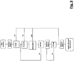
- fig. 9 shows the flow diagram of such strategy.
- the carburettor is equipped also with a thermosensitive heating element, which has a positive resistance coefficient depending on the temperature.
- This heating device reduces the formation of petrol vapour condensate on the cold walls of the carburettor supply ducts and further prevents the formation of ice in said ducts, which may occur in cold and damp climate conditions.
- the heating device is powered by the engine control unit if the room temperature is below a programmable threshold. Above such threshold, the heating device is deactivated, so as to restore a more advantageous electric equilibrium and avoid opposite undesirable phenomena, for example vapour-lock.
- Fig. 7 diagrammatically shows an exemplary functional diagram which defines how the PWM to be used for the oil pump is calculated.
- a possible simple strategy is that of detecting when N 1 ⁇ NT after which, the start-up mapping of the PWM control is to be applied to the oil pump until NT ⁇ N 3 after which the basic mapping must be used again.
- control system of the invention preferably uses as a parameter also the speed ratio (gear) entered.
- speed ratio gear
- specific ignition and carburation mappings are simultaneously adopted, so as to improve vehicle performance and driveability depending on the torque load opposing vehicle advancement.
- the inserted gear can be obtained. Based on such ratio (calculated in steps so as to identify a discrete number of values representing the various gears) specific ignition and carburation mappings are selected.
- variable control of the ignition spark advance can further be employed for controlling the minimum rpm in a closed loop (feedback) with a derivative-type adjustment.
- the spark advance value is reduced, so as to curb power and hence slow down the engine.
- the spark advance value is increased so as to boost power and increase revolution speed.
- a series of functions of a carburettor engine can be adjusted in an efficient, integrated and coordinated manner, with advantages in terms of operation regularity and efficiency at all rpms and in all climate conditions, hence reducing consumption and polluting emissions.
- the control system of the invention resorts to easily readable and derivable operation parameters, eliminating the use of complex components (such as lambda probes) and reducing power consumption, to the unquestionable benefit in terms of costs and ease of installation.
- the peculiar integrated control of functions allows an advantageous combined optimisation, which could not be obtained with known control systems which are dedicated for each specific function.
- the different operation variables are processed by a single control system, without having to be replicated and sent to different units, and that allows a simultaneous, synchronised and adequate control of the provided functions, avoiding deviations between the same due to the processing of said variables in different ways; the integrated control allows to have smooth and regular calibration, diagnosis and operation logics in the presence of faults, which are impossible with separate and mutually independent controls.
Landscapes
- Engineering & Computer Science (AREA)
- Chemical & Material Sciences (AREA)
- Combustion & Propulsion (AREA)
- Mechanical Engineering (AREA)
- General Engineering & Computer Science (AREA)
- Theoretical Computer Science (AREA)
- Signal Processing (AREA)
- Combined Controls Of Internal Combustion Engines (AREA)
- Electrical Control Of Air Or Fuel Supplied To Internal-Combustion Engine (AREA)
- Electrical Control Of Ignition Timing (AREA)
- Output Control And Ontrol Of Special Type Engine (AREA)
- Control Of The Air-Fuel Ratio Of Carburetors (AREA)
Claims (12)
- Ein elektronisches Steuerungssystem in einem mit gesteuerter Zündung versehenen, vergasergespeisten Verbrennungsmotor für ein Kraftfahrzeug, des Typs mit einer zentralen Steuereinheit, in der Steuerstrategien implementiert sind, um mindestens eine Elektroventileinrichtung anzusteuern, dadurch gekennzeichnet, dass die Elektroventileinrichtung (5) für die Einstellung der Emulsionsluft im Luftkreislauf der Sekundäremulsion eines Vergasers dient, der das Luft/Kraftstoff-Verhältnis des Brennstoffgemischs bestimmt, wobei die genannten Steuerstrategien auch zur Ansteuerung einer Zündeinrichtung mit einstellbarer Vorzündung implementiert sind, wobei die Steuerstrategien integriert sind und durchgeführt werden gemäß einer Grundabbildung, eine Funktion von Signalen, die die Position der Motorwelle über der Zeit repräsentieren, und gemäß Korrekturabbildungen (A %), eine Funktion zumindest von sekundären Parametern, die die Temperatur in Entsprechung des Motors (Teng) und die Position der Drosselklappen-Einstelleinrichtung (TPS) sind, wobei die Korrekturabbildungen (A %) in diskreten Intervallen, höchstens alle 10 Motorumdrehungen, neu berechnet werden und der Eingangswert der sekundären Parameter in diskreten Schritten berücksichtigt wird.
- System nach Anspruch 1, bei dem die Steuerstrategien auch mit der Steuerung einer Ölpumpe integriert sind, die Öl in ein Kraftstoffgemisch für den Motor einspeist.
- System nach Anspruch 1 oder 2, bei dem die Grundabbildung eine Funktion der Motordrehzahl (RPM) ist.
- System nach einem der Ansprüche 1 bis 3, wobei die Korrekturabbildung (A%) auch eine Funktion von Signalen ist, die die Raumtemperatur (Tamb) repräsentieren, so dass der Betrieb des Motors in den verschiedenen Umgebungsbedingungen optimiert wird.
- System nach einem der Ansprüche 1 bis 4, wobei die genannte Korrekturabbildung (A%) auch eine Funktion der Ableitung der Drehzahl der Motorwelle über der Zeit (dRPM/dT) ist.
- System nach einem der vorstehenden Ansprüche, wobei das Elektroventil für die Steuerung des Vergaserbetriebs durch Modulation der Dauer der Anwendung der Versorgungsspannung an einer Magnetspule innerhalb einer voreingestellten Periode bei konstanter Frequenz (PWM) angesteuert ist.
- System nach einem der vorhergehenden Ansprüche, wobei Standard-Grundabbildungen und mindestens eine weitere Start-up-Abbildung für die Start-up Phasen in der genannten Steuerungseinheit vorgesehen sind, wobei die Start-up-Abbildungen Funktionen von Signalen sind, die zumindest die Zahl der Verbrennungszyklen, die Motordrehzahl und die Motortemperatur repräsentieren.
- System nach Anspruch 7, bei dem die Start-up-Abbildung eingerichtet wird, wenn die Motordrehzahl (RPM) niedriger ist als ein voreingestellter Schwellenwert (RPM1) und die Motortemperatur (Teng) in einem vorgegebenen Temperaturbereich (TI-T2) liegt.
- System nach Anspruch 7 oder 8, wobei die Start-up-Abbildungen auch die Steuerung eines Heizwachselements einer automatischen Starterversorgung des Vergasers umfasst, die mit einer PWM-Methode gesteuert wird.
- System nach Anspruch 9, bei dem die Heizvorrichtung ein wärmeempfindliches Element umfasst, das ein positives Widerstand-Temperatur-Verhältnis hat.
- System nach einem der vorhergehenden Ansprüche, wobei die sekundären Parameter auch ein Signal umfassen, das den eingelegten Gang des Kraftfahrzeugs darstellt.
- System nach Anspruch 11, bei dem die Erkennung des eingelegten Gangs auf der Grundlage des Verhältnisses eines ersten Signals, das die Fahrzeuggeschwindigkeit darstellt, zu einem zweiten Signal, das die Motordrehzahl (RPM) darstellt, erfolgt.
Applications Claiming Priority (1)
| Application Number | Priority Date | Filing Date | Title |
|---|---|---|---|
| IT000483A ITMI20060483A1 (it) | 2006-03-16 | 2006-03-16 | Sistema di controllo elettronicio per motori a combustione interna alimentati a carburatore e ad eccezione comandata |
Publications (2)
| Publication Number | Publication Date |
|---|---|
| EP1835154A1 EP1835154A1 (de) | 2007-09-19 |
| EP1835154B1 true EP1835154B1 (de) | 2020-10-14 |
Family
ID=38093061
Family Applications (1)
| Application Number | Title | Priority Date | Filing Date |
|---|---|---|---|
| EP07103813.7A Ceased EP1835154B1 (de) | 2006-03-16 | 2007-03-09 | Elektronische Steuerung, System für vergasergetriebene Verbrennungsmotoren mit Kontrolle des Zündzeitpunktes |
Country Status (3)
| Country | Link |
|---|---|
| EP (1) | EP1835154B1 (de) |
| CN (1) | CN101037971B (de) |
| IT (1) | ITMI20060483A1 (de) |
Families Citing this family (5)
| Publication number | Priority date | Publication date | Assignee | Title |
|---|---|---|---|---|
| WO2011125079A1 (en) | 2010-04-09 | 2011-10-13 | Dell'orto S.P.A | System and method for controlling carburettor-supplied engines with lambda probe |
| CN102235290B (zh) * | 2010-04-30 | 2015-04-01 | 光阳工业股份有限公司 | 引擎点火系统的控制方法及装置 |
| JP2012193655A (ja) | 2011-03-16 | 2012-10-11 | Honda Motor Co Ltd | エンジンの点火時期設定装置 |
| US9464588B2 (en) | 2013-08-15 | 2016-10-11 | Kohler Co. | Systems and methods for electronically controlling fuel-to-air ratio for an internal combustion engine |
| US10054081B2 (en) | 2014-10-17 | 2018-08-21 | Kohler Co. | Automatic starting system |
Citations (3)
| Publication number | Priority date | Publication date | Assignee | Title |
|---|---|---|---|---|
| US5031593A (en) * | 1989-07-22 | 1991-07-16 | Prufrex-Electro-Apparatebau Inh. Helga Muller, geb. Dutschke | System for controlling the carburetor of an internal combustion engine |
| US5050553A (en) * | 1989-04-28 | 1991-09-24 | Prufrex-Elektro-Apparatebau Inh. Helga Muller, Geb. Dutschke | Capacitor ignition system |
| EP1266787A2 (de) * | 2001-06-14 | 2002-12-18 | Toyota Jidosha Kabushiki Kaisha | Verfahren und Vorrichtung zum automatisierten Abstellen eines Verbrennungsmotors und eines damit ausgestatteten Fahrzeugs |
Family Cites Families (9)
| Publication number | Priority date | Publication date | Assignee | Title |
|---|---|---|---|---|
| DE1278173B (de) * | 1964-07-06 | 1968-09-19 | Wtz Automobilbau Hohenstein Er | Schmiereinrichtung fuer Zweitakt-Otto-Motoren |
| DE2204192C3 (de) | 1972-01-29 | 1979-03-22 | Robert Bosch Gmbh, 7000 Stuttgart | Vorrichtung zur Verbesserung der Abgase einer Vergaser-Brennkraftmaschine |
| DE2918135C3 (de) * | 1979-05-05 | 1981-08-06 | Volkswagenwerk Ag, 3180 Wolfsburg | Verfahren zum Betrieb einer fremdgezündeten Brennkraftmaschine und Anordnung zur Durchführung des Verfahrens |
| JPS5783665A (en) * | 1980-11-14 | 1982-05-25 | Nippon Denso Co Ltd | Control method of engine rotation speed |
| IT1221935B (it) * | 1987-07-02 | 1990-08-31 | Morini Franco Motori Spa | Apparecchiatura di alimentazione ed accensione controllata per motori a combustione interna |
| SE9102629L (sv) * | 1991-09-11 | 1993-03-12 | Electrolux Ab | Anordning i foerbraenningsmotor |
| JPH08144815A (ja) | 1994-11-24 | 1996-06-04 | Keihin Seiki Mfg Co Ltd | 内燃機関の空燃比制御装置 |
| US6298824B1 (en) * | 1999-10-21 | 2001-10-09 | Brunswick Corporation | Engine control system using an air and fuel control strategy based on torque demand |
| US20030015175A1 (en) * | 2001-07-18 | 2003-01-23 | Andersson Martin N. | Ignition timing control system for light duty combustion engines |
-
2006
- 2006-03-16 IT IT000483A patent/ITMI20060483A1/it unknown
-
2007
- 2007-03-09 EP EP07103813.7A patent/EP1835154B1/de not_active Ceased
- 2007-03-16 CN CN2007100857876A patent/CN101037971B/zh not_active Expired - Fee Related
Patent Citations (3)
| Publication number | Priority date | Publication date | Assignee | Title |
|---|---|---|---|---|
| US5050553A (en) * | 1989-04-28 | 1991-09-24 | Prufrex-Elektro-Apparatebau Inh. Helga Muller, Geb. Dutschke | Capacitor ignition system |
| US5031593A (en) * | 1989-07-22 | 1991-07-16 | Prufrex-Electro-Apparatebau Inh. Helga Muller, geb. Dutschke | System for controlling the carburetor of an internal combustion engine |
| EP1266787A2 (de) * | 2001-06-14 | 2002-12-18 | Toyota Jidosha Kabushiki Kaisha | Verfahren und Vorrichtung zum automatisierten Abstellen eines Verbrennungsmotors und eines damit ausgestatteten Fahrzeugs |
Also Published As
| Publication number | Publication date |
|---|---|
| CN101037971B (zh) | 2011-07-06 |
| ITMI20060483A1 (it) | 2007-09-17 |
| EP1835154A1 (de) | 2007-09-19 |
| CN101037971A (zh) | 2007-09-19 |
Similar Documents
| Publication | Publication Date | Title |
|---|---|---|
| EP0239095B1 (de) | Methode und System zur Steuerung von Innen-Verbrennungsmaschinen | |
| US7654253B2 (en) | Detection of a humidity sensor failure in an internal combustion engine | |
| RU2570956C2 (ru) | Компенсация применения кислородосодержащего топлива в дизельном двигателе | |
| US5881552A (en) | Control system for internal combustion engines and control system for vehicles | |
| US4596164A (en) | Air-fuel ratio control method for internal combustion engines for vehicles | |
| US7246604B2 (en) | Engine control advantageously using humidity | |
| US7318409B2 (en) | Vehicle engine control system utilizing humidity sensor | |
| US10941703B2 (en) | Method and system for applying engine knock windows | |
| CN102337975A (zh) | 对柴油发动机中的含氧燃料的补偿 | |
| RU155448U1 (ru) | Система двигателя | |
| US7104228B2 (en) | Engine with variable cam timing and control advantageously using humidity sensor | |
| EP1835154B1 (de) | Elektronische Steuerung, System für vergasergetriebene Verbrennungsmotoren mit Kontrolle des Zündzeitpunktes | |
| US5701867A (en) | Apparatus for controlling the speed of an engine | |
| JPS59156831A (ja) | 最適シフト時期表示装置 | |
| US5495840A (en) | Fuel injection timing control device for an internal combustion engine | |
| US4526153A (en) | Air-fuel ratio control method for an internal combustion engine for vehicles in low load operating regions | |
| US4621600A (en) | Fuel supply control method for internal combustion engines at fuel cut operation | |
| GB2207781A (en) | I.c. engine fuel control | |
| EP1253308B1 (de) | Verfahren und Vorrichtung zur Regelung des Schadstoffausstosses von Verbrennungskraftmaschinen | |
| US7762924B2 (en) | Transmission shifting responsive to borderline knock limits | |
| GB2367383A (en) | A method for controlling an engine parameter in an internal combustion engine having a fuel vapour recovery system | |
| EP0646712B1 (de) | Vorrichtung zum Verändern des Drehmoments während besonderer Betriebszustände einer Brennkraftmaschine | |
| JP3496575B2 (ja) | 内燃機関の回転数制御装置 | |
| Colombo | Closed Loop Controlled Electronic Carburation System | |
| GB2181867A (en) | Method of controlling air-fuel ratio of air-fuel mixture for an internal combustion engine for vehicles |
Legal Events
| Date | Code | Title | Description |
|---|---|---|---|
| PUAI | Public reference made under article 153(3) epc to a published international application that has entered the european phase |
Free format text: ORIGINAL CODE: 0009012 |
|
| AK | Designated contracting states |
Kind code of ref document: A1 Designated state(s): AT BE BG CH CY CZ DE DK EE ES FI FR GB GR HU IE IS IT LI LT LU LV MC MT NL PL PT RO SE SI SK TR |
|
| AX | Request for extension of the european patent |
Extension state: AL BA HR MK YU |
|
| 17P | Request for examination filed |
Effective date: 20080318 |
|
| 17Q | First examination report despatched |
Effective date: 20080424 |
|
| AKX | Designation fees paid |
Designated state(s): ES FR IT |
|
| REG | Reference to a national code |
Ref country code: DE Ref legal event code: 8566 |
|
| RAP1 | Party data changed (applicant data changed or rights of an application transferred) |
Owner name: DELL'ORTO S.P.A. |
|
| STAA | Information on the status of an ep patent application or granted ep patent |
Free format text: STATUS: EXAMINATION IS IN PROGRESS |
|
| REG | Reference to a national code |
Ref country code: DE Ref legal event code: R079 Free format text: PREVIOUS MAIN CLASS: F02D0037020000 Ipc: F02P0005040000 |
|
| GRAP | Despatch of communication of intention to grant a patent |
Free format text: ORIGINAL CODE: EPIDOSNIGR1 |
|
| STAA | Information on the status of an ep patent application or granted ep patent |
Free format text: STATUS: GRANT OF PATENT IS INTENDED |
|
| RIC1 | Information provided on ipc code assigned before grant |
Ipc: F02P 5/04 20060101AFI20200506BHEP Ipc: F02D 3/04 20060101ALI20200506BHEP Ipc: F02D 37/02 20060101ALI20200506BHEP Ipc: F02P 5/15 20060101ALI20200506BHEP Ipc: F02D 41/02 20060101ALI20200506BHEP Ipc: F02D 41/06 20060101ALN20200506BHEP Ipc: F02D 11/10 20060101ALN20200506BHEP Ipc: F02D 35/00 20060101ALN20200506BHEP |
|
| INTG | Intention to grant announced |
Effective date: 20200605 |
|
| GRAS | Grant fee paid |
Free format text: ORIGINAL CODE: EPIDOSNIGR3 |
|
| GRAA | (expected) grant |
Free format text: ORIGINAL CODE: 0009210 |
|
| STAA | Information on the status of an ep patent application or granted ep patent |
Free format text: STATUS: THE PATENT HAS BEEN GRANTED |
|
| AK | Designated contracting states |
Kind code of ref document: B1 Designated state(s): ES FR IT |
|
| PG25 | Lapsed in a contracting state [announced via postgrant information from national office to epo] |
Ref country code: ES Free format text: LAPSE BECAUSE OF FAILURE TO SUBMIT A TRANSLATION OF THE DESCRIPTION OR TO PAY THE FEE WITHIN THE PRESCRIBED TIME-LIMIT Effective date: 20201014 |
|
| PLBE | No opposition filed within time limit |
Free format text: ORIGINAL CODE: 0009261 |
|
| STAA | Information on the status of an ep patent application or granted ep patent |
Free format text: STATUS: NO OPPOSITION FILED WITHIN TIME LIMIT |
|
| 26N | No opposition filed |
Effective date: 20210715 |
|
| PGFP | Annual fee paid to national office [announced via postgrant information from national office to epo] |
Ref country code: FR Payment date: 20230214 Year of fee payment: 17 |
|
| PGFP | Annual fee paid to national office [announced via postgrant information from national office to epo] |
Ref country code: IT Payment date: 20230215 Year of fee payment: 17 |
|
| P01 | Opt-out of the competence of the unified patent court (upc) registered |
Effective date: 20230516 |
|
| PG25 | Lapsed in a contracting state [announced via postgrant information from national office to epo] |
Ref country code: FR Free format text: LAPSE BECAUSE OF NON-PAYMENT OF DUE FEES Effective date: 20240331 |
|
| PG25 | Lapsed in a contracting state [announced via postgrant information from national office to epo] |
Ref country code: FR Free format text: LAPSE BECAUSE OF NON-PAYMENT OF DUE FEES Effective date: 20240331 |
|
| PG25 | Lapsed in a contracting state [announced via postgrant information from national office to epo] |
Ref country code: IT Free format text: LAPSE BECAUSE OF NON-PAYMENT OF DUE FEES Effective date: 20240309 |