EP1835205A2 - Hydrostatisches Getriebe - Google Patents
Hydrostatisches Getriebe Download PDFInfo
- Publication number
- EP1835205A2 EP1835205A2 EP07101556A EP07101556A EP1835205A2 EP 1835205 A2 EP1835205 A2 EP 1835205A2 EP 07101556 A EP07101556 A EP 07101556A EP 07101556 A EP07101556 A EP 07101556A EP 1835205 A2 EP1835205 A2 EP 1835205A2
- Authority
- EP
- European Patent Office
- Prior art keywords
- hydraulic
- motor
- capacity
- hydraulic motor
- shutoff valve
- Prior art date
- Legal status (The legal status is an assumption and is not a legal conclusion. Google has not performed a legal analysis and makes no representation as to the accuracy of the status listed.)
- Withdrawn
Links
Images



Classifications
-
- F—MECHANICAL ENGINEERING; LIGHTING; HEATING; WEAPONS; BLASTING
- F16—ENGINEERING ELEMENTS AND UNITS; GENERAL MEASURES FOR PRODUCING AND MAINTAINING EFFECTIVE FUNCTIONING OF MACHINES OR INSTALLATIONS; THERMAL INSULATION IN GENERAL
- F16H—GEARING
- F16H61/00—Control functions within control units of change-speed- or reversing-gearings for conveying rotary motion ; Control of exclusively fluid gearing, friction gearing, gearings with endless flexible members or other particular types of gearing
- F16H61/38—Control of exclusively fluid gearing
- F16H61/40—Control of exclusively fluid gearing hydrostatic
- F16H61/44—Control of exclusively fluid gearing hydrostatic with more than one pump or motor in operation
- F16H61/452—Selectively controlling multiple pumps or motors, e.g. switching between series or parallel
-
- F—MECHANICAL ENGINEERING; LIGHTING; HEATING; WEAPONS; BLASTING
- F16—ENGINEERING ELEMENTS AND UNITS; GENERAL MEASURES FOR PRODUCING AND MAINTAINING EFFECTIVE FUNCTIONING OF MACHINES OR INSTALLATIONS; THERMAL INSULATION IN GENERAL
- F16H—GEARING
- F16H61/00—Control functions within control units of change-speed- or reversing-gearings for conveying rotary motion ; Control of exclusively fluid gearing, friction gearing, gearings with endless flexible members or other particular types of gearing
- F16H61/38—Control of exclusively fluid gearing
- F16H61/40—Control of exclusively fluid gearing hydrostatic
- F16H61/4069—Valves related to the control of neutral, e.g. shut off valves
-
- F—MECHANICAL ENGINEERING; LIGHTING; HEATING; WEAPONS; BLASTING
- F16—ENGINEERING ELEMENTS AND UNITS; GENERAL MEASURES FOR PRODUCING AND MAINTAINING EFFECTIVE FUNCTIONING OF MACHINES OR INSTALLATIONS; THERMAL INSULATION IN GENERAL
- F16H—GEARING
- F16H61/00—Control functions within control units of change-speed- or reversing-gearings for conveying rotary motion ; Control of exclusively fluid gearing, friction gearing, gearings with endless flexible members or other particular types of gearing
- F16H61/38—Control of exclusively fluid gearing
- F16H61/40—Control of exclusively fluid gearing hydrostatic
- F16H61/44—Control of exclusively fluid gearing hydrostatic with more than one pump or motor in operation
- F16H61/444—Control of exclusively fluid gearing hydrostatic with more than one pump or motor in operation by changing the number of pump or motor units in operation
-
- F—MECHANICAL ENGINEERING; LIGHTING; HEATING; WEAPONS; BLASTING
- F16—ENGINEERING ELEMENTS AND UNITS; GENERAL MEASURES FOR PRODUCING AND MAINTAINING EFFECTIVE FUNCTIONING OF MACHINES OR INSTALLATIONS; THERMAL INSULATION IN GENERAL
- F16H—GEARING
- F16H47/00—Combinations of mechanical gearing with fluid clutches or fluid gearing
- F16H47/02—Combinations of mechanical gearing with fluid clutches or fluid gearing the fluid gearing being of the volumetric type
Definitions
- the present invention relates to a hydraulic power transmission device provided in a travel drive system, a winch drive system, or the like in a working machine such as a traveling type crane.
- the hydraulic power transmission device described in the publication includes a hydraulic pump which is driven by an engine and can discharge pressure oil in both directions, a plurality of variable displacement hydraulic motors connected in parallel with the hydraulic pump, and a common rotary shaft connected to output axes of the plurality of hydraulic motors in order to transmit power through a gear or the like respectively.
- a rotational speed of the rotary shaft from a low speed to a high speed, in order to obtain a torque necessary for acceleration, first, capacities of the plurality of hydraulic motors are increased. Next, the capacity of one of the hydraulic motors is reduced. In the case that the capacity becomes a minimum value, then the capacities of other hydraulic motors are reduced.
- a clutch is provided between the output axes of the hydraulic motors and the common rotary shaft, and in the case that the capacity of the hydraulic motors becomes the minimum value, the clutch is disconnected.
- the clutch is relatively expensive and heavy. This may cause an increase in cost or in weight of the device. Further, at the time of switching the clutch, especially at the time of connection, a shock may occur.
- the hydraulic motor Even if the clutch is disconnected, the hydraulic motor sometimes continues to rotate. That is, in the case of the hydraulic power transmission device installed in the working machine, as the variable displacement hydraulic motors, conventionally, hydraulic control type motors in which a capacity is controlled to be changed by oil pressure have been used. Generally, in the case of the variable displacement hydraulic motors, the minimum value of the capacity does not become zero. Accordingly, even if the capacity of the hydraulic control type hydraulic motor is set to be the minimum value and the clutch is disconnected, pressure oil at the minimum value flows into the hydraulic motor of the minimum capacity from the hydraulic pump. As the output axis of the hydraulic motor continues to rotate, the energy for the rotation is lost.
- a hydraulic pump capable of discharging pressure oil in both directions and a plurality of hydraulic motors connected in parallel with the hydraulic pump are provided.
- At least one hydraulic motor of the plurality of the hydraulic motors is a variable displacement type. Output axes of the plurality of hydraulic motors are connected to a common member in order to transmit power.
- the one hydraulic motor of the variable displacement type is an electronic control type which can change a capacity to zero.
- a shutoff valve is provided, which is for shutting off a supply of pressure oil from the hydraulic pump to the hydraulic motor in the case that the capacity of the hydraulic motor is zero. The shutoff valve communicates both sides of inlet/outlet of the hydraulic motor at the shutoff position.
- the supply of pressure oil from the hydraulic pump to the hydraulic motor is shut off by the shutoff valve. Accordingly, even if the hydraulic motor continues to rotate by the force from the common member, the hydraulic motor rotates in a state that the pressure is reduced. As a result, a torque loss or an energy loss due to the rotation of the hydraulic motor can be reduced. Further, the switching of the shutoff valve is executed in the case that the capacity of the hydraulic motor is zero and the flow rate at the shutoff valve is zero. Accordingly, the switching can be smoothly performed without effect of flow force.
- shutoff valve has been switched to the shutoff position, because the both sides of the inlet/outlet of the hydraulic motor, to which the supply of pressure oil is shut off by the shutoff valve, communicate with each other through the shutoff valve, hydraulic oil can be kept in the hydraulic motor and an appropriate lubrication can be performed. Further, in the case that the shutoff valve has been switched to the shutoff position, and in the case that the capacity of the hydraulic motor, to which the supply of pressure oil is shut off by the shutoff valve, is increased from zero due to a malfunction, the hydraulic oil circulates in a short circuit between the both sides of the inlet/outlet of the hydraulic motor and the shutoff valve, it is prevented that a high pressure is generated or a cavitation is generated.
- the hydraulic motors connected in parallel with the hydraulic pump are two hydraulic motors and both of the hydraulic motors are the variable displacement type.
- One hydraulic motor is the electronic control type capable of changing a capacity to zero
- the other hydraulic motor is a hydraulic control type incapable of changing a capacity to zero.
- the shutoff valve shuts off at the shutoff position only the entrance side of the hydraulic motor in a rotation direction to be mainly used, and maintains the communication between the exit side and the hydraulic pump side.
- the shutoff valve shuts off only the entrance side of the hydraulic motor in the rotation direction to be mainly used, and the communication between the exit side and the hydraulic pump side is maintained. Accordingly, if the hydraulic oil in the hydraulic motor leaks, the hydraulic oil is supplied into the hydraulic motor from the exit side, and an appropriate lubrication condition can be ensured. Further, the pressure at the exit side of the hydraulic motor is low because only an intake pressure of the hydraulic pump is applied thereto.
- the reduction effect of energy loss by the shutoff valve is not inhibited.
- the capacity of the hydraulic motor is increased from zero due to a malfunction in the case that the shutoff valve has been switched to the shutoff position, the generation of the high pressure or the generation of the cavitation at the exit side of the hydraulic motor can be prevented.
- a check valve is provided in parallel with the shutoff valve.
- the hydraulic oil circulates in the short circuit between the both sides of the inlet/outlet of the hydraulic motor and the shutoff valve.
- a back pressure valve is provided in parallel with the shutoff valve.
- the both sides of the inlet/outlet of the hydraulic motor, to which the supply of pressure oil is shut off by the shutoff valve communicate with each other through the shutoff valve, and the hydraulic oil is kept in the hydraulic motor.
- a pressure at the exit side of the hydraulic motor is controlled to be a value obtained by subtracting a differential pressure value of the back pressure valve from the intake pressure of the hydraulic pump, more appropriate lubrication can be performed.
- the hydraulic oil circulates in the short circuit between the both sides of the inlet/outlet of the hydraulic motor and the shutoff valve. Even if the hydraulic oil leaks inside, the hydraulic oil is supplied from the return conduit side to the hydraulic pump through the back pressure valve, and the generation of the cavitation can be surely prevented.
- a clutch can be provided between the output axis of the electronic control type variable displacement hydraulic motor and the common member.
- a clutch can be provided between the output axis of the electronic control type variable displacement hydraulic motor and the common member.
- Fig. 1 illustrates a schematic structure of a hydraulic power transmission device A according to a first embodiment of the present invention.
- the power transmission device A is installed in a travel drive system of a working machine.
- a variable displacement hydraulic pump 3 is connected to an engine 1 through a power divider 2.
- the hydraulic pump 3 can discharge pressure oil in both directions.
- Output axes 6a and 7a of the both oil pressure motors 6 and 7 are connected to a rotary shaft 9, which is a common member, in order to transmit power through a power combine 8, which includes a gear or the like.
- the rotary shaft 9 drives left and right hubs 11, 11 and wheels 12, 12 through a differential gear 10 or the like.
- Both of the two hydraulic motors 6 and 7 are variable displacement type.
- One of the motors, that is, the hydraulic motor 6 is an electronic control type in which an inclination angle or a capacity is controlled to be changed by a current value, and the capacity can be changed to be zero.
- the other hydraulic motor 7 is a hydraulic control type in which an inclination angle or a capacity is controlled to be changed by an oil pressure, and the capacity cannot be changed to be zero.
- the main conduits 4 and 5 are branched at the sides of the hydraulic motors 6 and 7 to be two conduits respectively, that is, a total of four conduits.
- the four branched conduits 4a, 4b, 5a, and 5b are connected to the inlet/outlet of the corresponding hydraulic motors 6 and 7 respectively.
- a shutoff valve 15 is provided, which shuts off the supply of the pressure oil from the hydraulic pump 3 to the hydraulic motor 6 in the case that the capacity of the hydraulic motor 6 is zero, to the branched conduits 4a and 5a connected to the both sides of the inlet/outlet of the electronic control type hydraulic motor 6.
- the shutoff valve 15, as enlarged and shown in detail in Fig.
- An electronic control part 6b of the electronic control type hydraulic motor 6 is controlled by a controller 16.
- the controller 16 controls an electric part (for example, an electromagnetic part of a pilot valve) of a hydraulic control part 7b of the hydraulic control type hydraulic motor 7, an electromagnetic part of the shutoff valve 15, or the like.
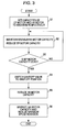
- the control of the controller 16 is executed, for example, in a case of changing rotational speeds of the wheels 12, that is, travel speeds of the working device, from a low speed to a high speed, according to the flowchart illustrated in Fig. 3.
- the meaning of "low speed" in this specification involves zero.
- both capacities of the electronic control type hydraulic motor (hereinafter, referred to as EP motor) 6 and the hydraulic control type hydraulic motor (hereinafter, referred to as HA motor) 7 are set to be maximum.
- EP motor electronic control type hydraulic motor
- HA motor hydraulic control type hydraulic motor
- the capacity of the EP motor 6 is reduced.
- step S3 whether the capacity of the EP motor 6 is zero or not is determined. If the determination is NO, the process returns to step S2, and if the determination is YES, the process proceeds to step S4.
- step S4 the shutoff valve 15 is switched from a communication position M to the shutoff position N. Then, at step S5, the capacity of the HA motor 7 is reduced, at step S6, the capacity of the HA motor 7 is set to be minimum, and the control is completed.
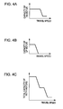
- the capacity control of the HA motor 7 to changing travel speeds is shown in Fig. 4A.
- the capacity control of the EP motor 6 to changing travel speeds is shown in Fig. 4B.
- the capacity control of the total of the both motors 6 and 7 is shown in Fig. 4C.
- the shutoff valve 15 is switched from the communication position M to the shutoff position N, and the supply of the pressure oil from the hydraulic pump 3 to the EP motor 6 is shut off. Accordingly, even if the EP motor 6 continues to rotate with rotating force from the rotary shaft 9, the EP motor 6 rotates in a state that the pressure is reduced. As a result, an energy loss due to the rotation of the EP motor 6 can be reduced, and the efficiency can be highly increased.
- the switching of the shutoff valve 15 is executed in the case that the capacity of the EP motor 6 is zero and the flow rate at the shutoff valve is zero, and therefore, flow force does not act on. Accordingly, the switching of the shutoff valve 15 can be smoothly carried out.
- shutoff valve 15 has been switched to the shutoff position N, because the both sides of the inlet/outlet of the EP motor 6 communicate with each other through the shutoff valve 15, hydraulic oil can be kept in the EP motor 6 and an appropriate lubrication can be performed. Further, in the case that the capacity of the EP motor 6 is increased from zero due to a malfunction in the case that the shutoff valve 15 has been switched to the shutoff position N, or in the case that the shutoff valve 15 is switched to the shutoff position N due to a malfunction in the case that the capacity of the EP motor 6 is not zero, the hydraulic oil circulates in a short circuit between the both sides of the inlet/outlet of the EP motor 6 and the shutoff valve 15. Accordingly, it is prevented that a high pressure is generated or a cavitation is generated.
- the capacity of the HA motor 7 is reduced. Accordingly, power transmission can be effectively carried out over a wide range of travel speeds. Moreover, in the case that the EP motor 6 becomes out of control due to a failure in electric system and the capacity of the EP motor 6 becomes zero, the capacity of the HA motor 7 does not become zero. Accordingly, a required minimum amount of power can be transmitted to the common rotary shaft 9 or the wheels 12, and very effective in the view of measures for troubles.
- Fig. 5 illustrates a schematic structure of a hydraulic power transmission device B according to the second embodiment of the present invention.
- a basic structure of the power transmission device B is similar to that of the power transmission device A according to the first embodiment. Accordingly, the same numerals are given to the same members and those descriptions are omitted.
- a shutoff valve 20 shuts off a supply of pressure oil from the hydraulic pump 3 to the EP motor 6 in the case that the capacity of the EP motor 6 is zero. That is, the shutoff valve 20, as enlarged and shown in detail in Fig. 6, similarly to the case of the shutoff valve 15 in the first embodiment, includes an electromagnetic type four-ports/two-positions type switching valve. However, at the shutoff position N, the A port and the B port of the EP motor 6 side communicate with each other and the both sides of the inlet/outlet of the EP motor 6 also communicate with each other.
- the shutoff valve 20 shuts off only the entrance side of the EP motor 6 in the forward rotation direction to be mainly used, and the communication between the exit side and the hydraulic pump 3 side is maintained. Accordingly, if the hydraulic oil in the EP motor 6 leaks, the hydraulic oil is supplied into the EP motor 6 from the exit side, and an appropriate lubrication condition can be ensured. Further, since only an intake pressure of the hydraulic pump 3 is applied to the pressure at the exit side of the EP motor 6, the pressure at the exit side of the EP motor 6 is low. Accordingly, the reduction effect of energy loss by the shutoff valve 20 is not inhibited.
- the generation of the high pressure or the generation of the cavitation at the exit side of the EP motor 6 can be prevented more firmly than the case of the first embodiment.
- the reduction effect of energy loss by the shutoff valve 20 can be obtained, and at the time of backward traveling, the effect can not be obtained.
- the rate of the backward traveling in the whole traveling time is low, so substantially this is not a big problem.
- Fig. 7 illustrates a schematic structure of a hydraulic power transmission device C according to the third embodiment of the present invention.
- a basic structure of the power transmission device C is similar to that of the power transmission device A according to the first embodiment. Accordingly, the same numerals are given to the same members and those descriptions are omitted.
- a check valve 22 which is arranged in parallel with the shutoff valve 15 and allows a flow into the EP motor 6 is provided between an exit side of the EP motor 6 in the forward rotation direction to be mainly used and the branched conduit 5a of the main conduit 5 which is a return conduit to the hydraulic pump 3.
- the hydraulic oil circulates in the short circuit between the both sides of the inlet/outlet of the EP motor 6 and the shutoff valve 15.
- the hydraulic oil is supplied from the branched conduit 5a side of the main conduit 5 through the check valve 22, and the generation of the cavitation can be prevented more firmly than the case of the first embodiment.
- Fig. 8 illustrates a schematic structure of a hydraulic power transmission device D according to the fourth embodiment of the present invention.
- a basic structure of the power transmission device D is similar to that of the power transmission device A according to the first embodiment. Accordingly, the same numerals are given to the same members and those descriptions are omitted.
- a back pressure valve 24 which is arranged in parallel with the shutoff valve 15 and allows a flow into the EP motor 6 is provided between the exit side of the EP motor 6 in the forward rotation direction to be mainly used and the branched conduit 5a of the main conduit 5 which is the return conduit to the hydraulic pump 3.
- a pressure at the exit side of the EP motor 6 is controlled to be a value obtained by subtracting a differential pressure value of the back pressure valve 24 from the intake pressure of the hydraulic pump 3, a more appropriate lubrication can be performed as compared to the case of the first embodiment.
- the hydraulic oil circulates in the short circuit between the both sides of the inlet/outlet of the EP motor 6 and the shutoff valve 15.
- the hydraulic oil is supplied from the branched conduit 5a side of the main conduit 5 through the back pressure valve 24, and the generation of the cavitation can be prevented more firmly than the case of the first embodiment.
- Fig. 9 illustrates a schematic structure of a hydraulic power transmission device E according to the fifth embodiment of the present invention.
- a basic structure of the power transmission device E is similar to that of the power transmission device A according to the first embodiment. Accordingly, the same numerals are given to the same members and those descriptions are omitted.
- the efficiency can be further increased as compared with the case of the first embodiment.
- the present invention is not limited to the above-described embodiments 1 to 5, but covers various modifications.
- the hydraulic power transmission devices A to E which are provided with the two variable displacement hydraulic motors 6 and 7 which are connected in parallel with the hydraulic pump 3.
- the present invention is not limited to the case in which the number of the hydraulic motors is two, but the number of the hydraulic motors can be more than two.
- all of the hydraulic motors are not necessary to be the variable displacement type, but it is enough that at least one hydraulic motor is the variable displacement type.
- the hydraulic power transmission devices A to E according to each embodiment are installed in the travel drive system of the working machine.
- the present invention can also be applied to hydraulic power transmission devices which are installed in winch drive systems such as a traveling type crane.
- winch drive systems such as a traveling type crane.
- a common member to which a plurality of output axes of a hydraulic motor are connected in order to transmit power not only the drive axis of the winch, but also a drum of the winch can be used.
- a rotation direction of the hydraulic motor to be mainly used can be either a lifting direction or a lowering direction.
- a hydraulic power transmission device A includes a hydraulic pump 3 capable of discharging pressure oil in both directions and a plurality of hydraulic motors 6 and 7 connected in parallel with the hydraulic pump.
- a hydraulic pump 3 capable of discharging pressure oil in both directions
- a plurality of hydraulic motors 6 and 7 connected in parallel with the hydraulic pump.
- at least one hydraulic motor is a variable displacement type.
- Output axes 6a and 7a of the plurality of hydraulic motors are connected to a common member 9 in order to transmit power.
- the one hydraulic motor 6 of the variable displacement type is an electronic control type capable of changing a capacity to zero.
- a shutoff valve 15 is provided, which is for shutting off a supply of pressure oil from the hydraulic pump to the hydraulic motor in the case that the capacity of the hydraulic motor 6 is zero.
- the shutoff valve 15 communicates both sides of inlet/outlet of the hydraulic motor at the shutoff position. Accordingly, in the present invention, energy loss can be reduced and highly effective.
Landscapes
- Engineering & Computer Science (AREA)
- General Engineering & Computer Science (AREA)
- Mechanical Engineering (AREA)
- Control Of Fluid Gearings (AREA)
- Fluid-Pressure Circuits (AREA)
Applications Claiming Priority (1)
| Application Number | Priority Date | Filing Date | Title |
|---|---|---|---|
| JP2006073478A JP2007247821A (ja) | 2006-03-16 | 2006-03-16 | 油圧式動力伝達装置 |
Publications (2)
| Publication Number | Publication Date |
|---|---|
| EP1835205A2 true EP1835205A2 (de) | 2007-09-19 |
| EP1835205A3 EP1835205A3 (de) | 2010-06-09 |
Family
ID=37907690
Family Applications (1)
| Application Number | Title | Priority Date | Filing Date |
|---|---|---|---|
| EP07101556A Withdrawn EP1835205A3 (de) | 2006-03-16 | 2007-02-01 | Hydrostatisches Getriebe |
Country Status (2)
| Country | Link |
|---|---|
| EP (1) | EP1835205A3 (de) |
| JP (1) | JP2007247821A (de) |
Cited By (3)
| Publication number | Priority date | Publication date | Assignee | Title |
|---|---|---|---|---|
| WO2013032370A1 (en) * | 2011-08-26 | 2013-03-07 | Volvo Construction Equipment Ab | Drive control method and system for operating a hydraulic driven work machine |
| CN107339289A (zh) * | 2017-08-15 | 2017-11-10 | 杭州力龙液压有限公司 | 用于液压动力装置的防吸空装置及液压动力组件 |
| CN118224140A (zh) * | 2024-03-27 | 2024-06-21 | 中国铁建重工集团股份有限公司 | 液压随动控制系统及车辆 |
Families Citing this family (2)
| Publication number | Priority date | Publication date | Assignee | Title |
|---|---|---|---|---|
| JP4687727B2 (ja) * | 2008-02-26 | 2011-05-25 | コベルコクレーン株式会社 | 作業車両の動力伝達装置 |
| JP5269699B2 (ja) * | 2009-06-10 | 2013-08-21 | 株式会社神戸製鋼所 | 油圧式作業車両 |
Family Cites Families (3)
| Publication number | Priority date | Publication date | Assignee | Title |
|---|---|---|---|---|
| DE19751001A1 (de) * | 1997-11-18 | 1999-05-20 | Zahnradfabrik Friedrichshafen | Verfahren und Vorrichtung zur Verhinderung der Zugkraftunterbrechung beim Zu- und Abschalten von Hydromotoren |
| DE19858958B4 (de) * | 1997-12-12 | 2006-08-17 | Komatsu Ltd. | Vorrichtung zur Steuerung mehrerer ölhydraulischer Motoren sowie einer Kupplung |
| JP2001200907A (ja) * | 2000-01-14 | 2001-07-27 | Shin Caterpillar Mitsubishi Ltd | 動力伝達装置 |
-
2006
- 2006-03-16 JP JP2006073478A patent/JP2007247821A/ja not_active Withdrawn
-
2007
- 2007-02-01 EP EP07101556A patent/EP1835205A3/de not_active Withdrawn
Non-Patent Citations (1)
| Title |
|---|
| None |
Cited By (6)
| Publication number | Priority date | Publication date | Assignee | Title |
|---|---|---|---|---|
| WO2013032370A1 (en) * | 2011-08-26 | 2013-03-07 | Volvo Construction Equipment Ab | Drive control method and system for operating a hydraulic driven work machine |
| CN103782069A (zh) * | 2011-08-26 | 2014-05-07 | 沃尔沃建筑设备公司 | 用于操作液压驱动式工程机械的驱动控制方法和系统 |
| CN103782069B (zh) * | 2011-08-26 | 2016-05-18 | 沃尔沃建筑设备公司 | 用于操作液压驱动式工程机械的驱动控制方法和系统 |
| US9506222B2 (en) | 2011-08-26 | 2016-11-29 | Volvo Construction Equipment Ab | Drive control method and system for operating a hydraulic driven work machine |
| CN107339289A (zh) * | 2017-08-15 | 2017-11-10 | 杭州力龙液压有限公司 | 用于液压动力装置的防吸空装置及液压动力组件 |
| CN118224140A (zh) * | 2024-03-27 | 2024-06-21 | 中国铁建重工集团股份有限公司 | 液压随动控制系统及车辆 |
Also Published As
| Publication number | Publication date |
|---|---|
| EP1835205A3 (de) | 2010-06-09 |
| JP2007247821A (ja) | 2007-09-27 |
Similar Documents
| Publication | Publication Date | Title |
|---|---|---|
| EP2607717B1 (de) | Elektrohydraulisches antriebssystem für eine arbeitsmaschine | |
| US6989640B2 (en) | Actuator driving device of working machine | |
| US7578761B2 (en) | Hydraulic circuit control device | |
| RU2566831C2 (ru) | Тяговая и передающая движение установка, в частности, для винтокрылого летательного аппарата | |
| EP2479351A1 (de) | Hybridbaumaschine | |
| EP1835205A2 (de) | Hydrostatisches Getriebe | |
| EP3037589B1 (de) | Baumaschine | |
| WO2011073774A2 (en) | Piecewise hydraulic power transmission system | |
| CN110375053B (zh) | 平地机 | |
| JP2010126047A (ja) | ハイブリッド車両用駆動装置 | |
| US11981194B2 (en) | Method for operating a drivetrain for a work machine, drivetrain for a work machine, and work machine | |
| US20220307595A1 (en) | Hydraulic circuit architecture with enhanced operation efficency | |
| CN115450967A (zh) | 用于混动变速箱的液压系统及汽车 | |
| WO2014209933A1 (en) | Hydrostatic-parallel hydraulic hybrid architectures | |
| KR20140137022A (ko) | 굴삭기 주행 연비 절감 시스템 | |
| JP6442270B2 (ja) | 建設機械の油圧駆動システム | |
| EP4428087A1 (de) | Hydraulisches antriebssystem, arbeitsmaschine und steuerungsverfahren für hydraulisches antriebssystem | |
| CN108602431B (zh) | 传动系统 | |
| US20120006155A1 (en) | Shift transmission | |
| WO2019004156A1 (ja) | 油圧駆動システム | |
| US20100146960A1 (en) | Externally mounted variator for split torque transmission | |
| CN108602432B (zh) | 传动系统 | |
| EP1894765A2 (de) | Hydraulisches Antriebssystem | |
| KR102764052B1 (ko) | 보기류 펌프의 상시 운용이 가능한 친환경 특장차의 구동 시스템 | |
| KR102631503B1 (ko) | 감속기어가 내장된 변속 유체 커플링 |
Legal Events
| Date | Code | Title | Description |
|---|---|---|---|
| PUAI | Public reference made under article 153(3) epc to a published international application that has entered the european phase |
Free format text: ORIGINAL CODE: 0009012 |
|
| 17P | Request for examination filed |
Effective date: 20070201 |
|
| AK | Designated contracting states |
Kind code of ref document: A2 Designated state(s): AT BE BG CH CY CZ DE DK EE ES FI FR GB GR HU IE IS IT LI LT LU LV MC NL PL PT RO SE SI SK TR |
|
| AX | Request for extension of the european patent |
Extension state: AL BA HR MK YU |
|
| PUAL | Search report despatched |
Free format text: ORIGINAL CODE: 0009013 |
|
| AK | Designated contracting states |
Kind code of ref document: A3 Designated state(s): AT BE BG CH CY CZ DE DK EE ES FI FR GB GR HU IE IS IT LI LT LU LV MC NL PL PT RO SE SI SK TR |
|
| AX | Request for extension of the european patent |
Extension state: AL BA HR MK RS |
|
| RIC1 | Information provided on ipc code assigned before grant |
Ipc: F16H 61/452 20100101ALI20100715BHEP Ipc: F16H 61/4069 20100101ALI20100715BHEP Ipc: F16H 61/444 20100101AFI20100715BHEP |
|
| GRAP | Despatch of communication of intention to grant a patent |
Free format text: ORIGINAL CODE: EPIDOSNIGR1 |
|
| RIN1 | Information on inventor provided before grant (corrected) |
Inventor name: HORI, NAOTOKOBE CORP. RESEARCH LABORATORIES Inventor name: SUGANO, NAOKIKOBE CORP. RESEARCH LABORATORIES Inventor name: TERASAKA, JOJIOKUBO PLANT IN KOBELCO CRANES CO., L Inventor name: TSUNOO, TAISUKEOKUBO PLANT IN KOBELCO CRANES CO., Inventor name: KOBAYASHI, TAKAHIROOKUBO PLANT IN KOBELCO CRANES C |
|
| AKX | Designation fees paid |
Designated state(s): AT BE BG CH CY CZ DE DK EE ES FI FR GB GR HU IE IS IT LI LT LU LV MC NL PL PT RO SE SI SK TR |
|
| STAA | Information on the status of an ep patent application or granted ep patent |
Free format text: STATUS: THE APPLICATION IS DEEMED TO BE WITHDRAWN |
|
| 18D | Application deemed to be withdrawn |
Effective date: 20110126 |