EP1835245A2 - Dispositif destiné à la conservation et/ou le transport de glaçons - Google Patents
Dispositif destiné à la conservation et/ou le transport de glaçons Download PDFInfo
- Publication number
- EP1835245A2 EP1835245A2 EP07005444A EP07005444A EP1835245A2 EP 1835245 A2 EP1835245 A2 EP 1835245A2 EP 07005444 A EP07005444 A EP 07005444A EP 07005444 A EP07005444 A EP 07005444A EP 1835245 A2 EP1835245 A2 EP 1835245A2
- Authority
- EP
- European Patent Office
- Prior art keywords
- channel
- ice cubes
- rotation
- ice
- rotary member
- Prior art date
- Legal status (The legal status is an assumption and is not a legal conclusion. Google has not performed a legal analysis and makes no representation as to the accuracy of the status listed.)
- Withdrawn
Links
- 229910001220 stainless steel Inorganic materials 0.000 claims description 10
- 239000010935 stainless steel Substances 0.000 claims description 10
- 239000004033 plastic Substances 0.000 claims description 9
- 229920000515 polycarbonate Polymers 0.000 claims description 6
- 239000004417 polycarbonate Substances 0.000 claims description 5
- XLYOFNOQVPJJNP-UHFFFAOYSA-N water Substances O XLYOFNOQVPJJNP-UHFFFAOYSA-N 0.000 claims description 3
- 239000003795 chemical substances by application Substances 0.000 claims 1
- 238000003860 storage Methods 0.000 description 7
- 230000000903 blocking effect Effects 0.000 description 5
- 238000005070 sampling Methods 0.000 description 4
- 244000052616 bacterial pathogen Species 0.000 description 3
- 230000035515 penetration Effects 0.000 description 3
- 230000001154 acute effect Effects 0.000 description 2
- 239000000356 contaminant Substances 0.000 description 2
- 230000003670 easy-to-clean Effects 0.000 description 2
- 238000007710 freezing Methods 0.000 description 2
- 230000008014 freezing Effects 0.000 description 2
- 238000009413 insulation Methods 0.000 description 2
- 239000004425 Makrolon Substances 0.000 description 1
- 230000005540 biological transmission Effects 0.000 description 1
- 238000004140 cleaning Methods 0.000 description 1
- 238000011109 contamination Methods 0.000 description 1
- 238000001816 cooling Methods 0.000 description 1
- 230000001419 dependent effect Effects 0.000 description 1
- 238000011161 development Methods 0.000 description 1
- 230000018109 developmental process Effects 0.000 description 1
- 238000000605 extraction Methods 0.000 description 1
- 238000010438 heat treatment Methods 0.000 description 1
- 238000004519 manufacturing process Methods 0.000 description 1
- 239000000463 material Substances 0.000 description 1
- 238000000465 moulding Methods 0.000 description 1
- 210000000056 organ Anatomy 0.000 description 1
- 238000004806 packaging method and process Methods 0.000 description 1
- 238000002360 preparation method Methods 0.000 description 1
- 238000000926 separation method Methods 0.000 description 1
- 238000005303 weighing Methods 0.000 description 1
Images

Classifications
-
- F—MECHANICAL ENGINEERING; LIGHTING; HEATING; WEAPONS; BLASTING
- F25—REFRIGERATION OR COOLING; COMBINED HEATING AND REFRIGERATION SYSTEMS; HEAT PUMP SYSTEMS; MANUFACTURE OR STORAGE OF ICE; LIQUEFACTION SOLIDIFICATION OF GASES
- F25C—PRODUCING, WORKING OR HANDLING ICE
- F25C5/00—Working or handling ice
- F25C5/20—Distributing ice
- F25C5/24—Distributing ice for storing bins
-
- F—MECHANICAL ENGINEERING; LIGHTING; HEATING; WEAPONS; BLASTING
- F25—REFRIGERATION OR COOLING; COMBINED HEATING AND REFRIGERATION SYSTEMS; HEAT PUMP SYSTEMS; MANUFACTURE OR STORAGE OF ICE; LIQUEFACTION SOLIDIFICATION OF GASES
- F25C—PRODUCING, WORKING OR HANDLING ICE
- F25C2500/00—Problems to be solved
- F25C2500/08—Sticking or clogging of ice
Definitions
- the invention relates to a device for storing and / or transporting ice cubes, which has a channel for storing and / or transporting the ice cubes, and an arrangement for producing and providing ice cubes, with such a device and with a plurality of ice makers.
- Machines for the preparation of ice cubes are known from the prior art. For example, in supermarkets, fishing companies, ice factories, catering companies, large catering or wholesale markets, but also in larger catering facilities and bars ice cube machines are required with particularly large capacities. Since the need for ice cubes is not constant and as well as the production capacity of each ice machine is subject to different influences, in particular the ambient temperature, it is usually advantageous from an economic point of view to hold several ice machines and operate them only according to demand. Industrial ice cube machines often have a storage device for finished ice cubes, from which they can be removed if necessary, possibly via so-called dispenser or dispenser. The transport of ice cubes usually takes place in suitable containers.
- the disadvantage is that the removal of large quantities of ice cubes from different ice cube machines is cumbersome and expensive and that the dislocated operation of optionally cooled storage devices is uneconomical.
- a significant number of ice cubes are damaged during removal by pouring or with the help of blades, which leads to rejects in certain areas, especially in the catering industry.
- the transfer of the ice cubes into transport containers does not always meet the particularly high hygiene requirements in food processing.
- the object of the present invention is to provide an apparatus for storing and / or transporting ice cubes, which avoids the disadvantages of the prior art.
- the object is achieved by a device for storing and / or transporting ice cubes with the features of the characterizing part of patent claim 1 and / or with the features of patent claim 5.
- the device according to the invention for storing and / or transporting ice cubes requires less energy for the storage of ice cubes of several ice cube machines and that the extraction of ice cubes is particularly easy, comfortable, especially without the Damage ice cubes.
- the device for storing and / or transporting ice cubes has a gutter.
- a gutter in the sense of this invention has at least one bottom area and side walls and is configured, for example, in the form of a U and / or V, angular and / or rounded.
- the extent of the channel according to the invention in its longitudinal direction, ie transport direction, is significantly greater than the width of the channel from side wall to side wall.
- several ice cube producers can be arranged in the region of the trough, the ice cubes produced in the ice cube maker being collected and stored in the trough.
- ice cube maker a device is referred to, are made with the ice cube, wherein the term ice cube in the context of this invention is not limited to cubic forms. Ice cubes can be in addition to whole ice cubes in any three-dimensional form so-called Hohleisorulfel.
- a rotary member extends substantially over its entire length, wherein the rotary member is rotatably arranged according to the invention.
- the person skilled in the art will understand that the axis of rotation about which the rotary member is rotatable extends in the longitudinal direction of the channel.
- the ice cubes in the channel can be transported along the channel during a rotation of the rotary member in a first direction of rotation, thus for example in a clockwise direction.
- the ice cubes are einzelzelbar.
- Singling means, in particular, that the ice cubes are mixed in order to prevent freezing and, if appropriate, to separate ice cubes frozen against each other or on the gutter.
- a removal point is located, for example, at one end of the channel, wherein the transport of the ice cubes takes place in a first direction of rotation, preferably in the direction of such a removal point, by the rotation of the rotation element.
- the rotation member according to the invention is advantageously used as a combined transport and separating organ.
- the rotation member can be removed, which makes the cleaning of the device according to the invention particularly simple.
- the rotation of the rotary member is preferably controllable by means of a controller, for example by an operator or automated.
- the rotation in the first direction of rotation is particularly preferably dependent on a need for ice cubes, which are provided, for example, at a sampling point. If there is a great need, for example, the transport of the ice cubes can be accelerated.
- the rotation in the second direction of rotation is particularly preferably carried out at definable intervals, for example, after the rotation member has not been moved for a certain time.
- the inventive control it is advantageously possible to provide the required amount of ice cubes available.
- the singulation and mixing of the ice cubes can be automated, so that it can not come to a freeze.
- the rotary member preferably comprises at least one strand arranged helically about its axis of rotation, wherein the strand is particularly preferably a tube or rod made of stainless steel, which is arranged by means of struts on a central shaft.
- the rotary member is so advantageous and easy rotatably driven via the central shaft, for example by a motor or a transmission. Also conceivable is the arrangement of several strands that are a multiple helix form.
- the length of the channel and / or the length of the rotary member can be adapted by modular expansion.
- the channel is composed, for example, of channel segments and can thus be advantageously adapted to the number of ice cube producers.
- the rotation member is composed of segments and so adapted to the length of the groove.
- the channel of the device for storing and / or transporting ice cubes has at least one slide-like feed, wherein the ice cubes can be transported by an ice cube maker via the slide-like feed into the channel.
- the advantage of the embodiment is that the ice cubes do not fall into a storage container, but controlled, slipping over the feed into the gutter. As a result, damage to the ice cubes by impact at high speed is advantageously avoided.
- the feed opens at an acute angle to the horizontal in the gutter. The angle is very particularly preferably between 0 ° and 25 °.
- a supply can be provided for a plurality of ice cube producers for each ice cube producer. It would also be conceivable to transport the ice cubes of several ice cube generators collected via a feed into the gutter.
- the feeders according to the invention are preferably adaptable, in particular in length, so that the position of the ice cube generators to the trough can advantageously be varied.
- the ice cube generators can be arranged at different distances from the channel, or in particular at different heights.
- the feeder may be made of any suitable material.
- the supply consists at least partially of a plastic and / or is at least partially coated with a plastic, more preferably polycarbonate.
- the ice cubes are advantageously not damaged by the smooth and comparatively compliant surface of the plastic.
- the channel is designed double-walled, particularly preferably made of stainless steel.
- the double wall allows, for example, a particularly good thermal insulation of the channel, so that the temperature of the ice cubes is less expensive.
- Stainless steel is particularly durable and insensitive. The device is therefore particularly easy to clean.
- the channel has a cover which largely closes the channel towards the top.
- the device according to the invention preferably forms an all-sided closed system. As a result, the penetration of germs and / or contamination into the channel is prevented in a particularly advantageous manner, so that particularly high hygiene requirements are met.
- the channel has at least one head end an opening as a removal point, which can be closed by a locking member.
- a removal point By providing the ice cubes at the sampling point, they are particularly easy to remove.
- the obturator such as a slide, prevents the escape of ice cubes and heating of the interior of the trough, while no removal of ice cubes takes place. In particular, the penetration of germs and / or contaminants via the removal point is advantageously minimized.
- a device for further processing of the ice cubes at the head end of the channel can be coupled, for example, a dispenser or a packaging machine, which is particularly preferably equipped with a weighing device.
- a dispenser or a packaging machine which is particularly preferably equipped with a weighing device.
- the device according to the invention is a system which is essentially closed on all sides, so that the temperature inside is particularly constant and advantageously particularly high hygiene requirements are met.
- the ice cube will not come into contact with the environment.
- the channel has a drainage for melt water, which runs for example in the space between the double wall.
- Another object of the invention is an arrangement for producing and providing ice cubes, with a device according to the invention described above and a plurality of ice makers, wherein the ice maker can be arranged on both sides of the channel, namely several ice makers along the channel behind one another and / or more Ice cube maker on top of each other.
- the arrangement has the advantage that the capacity for making ice cubes is adaptable to the need by having just as many ice makers thereon and / or operating as needed.
- the storage of the ice cubes in the channel according to the invention advantageously allows a more effective temperature control than in individual containers per ice cube maker.
- the ice cubes can be conveniently provided at a common sampling point.
- the arrangement according to the invention has a large and simultaneously variable storage capacity.
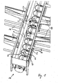
- FIG. 1 shows a device according to the invention in a perspective view.
- FIG. 2 shows a schematic longitudinal section of the arrangement according to the invention.
- FIG. 3 shows a schematic cross-sectional view of the arrangement according to the invention according to FIG . 2 .
- a device according to the invention is shown in perspective.
- a rotary member 2 is arranged, which extends substantially over the entire length of the channel 1.
- the bottom area of the Channel 1 is preferably semicircular in cross-section, so that the smallest possible distance between the rotary member 2 and the channel wall.
- the channel 1 is, for example, double-walled and executed in stainless steel.
- the rotary member 2 comprises a helical strand 8, here a tube 8 made of stainless steel, which winds around a central shaft 6 and is connected thereto via struts 7.
- the central shaft 6 is rotationally driven by a not shown drive means.
- the ice cubes 3 are conveyed in the direction of a head end 10 of the channel 1 to.
- a removal point 11 which in particular can be closed with a blocking element 12 (FIG. 2).
- the blocking member 12, for example a flap, can be arranged at both ends of the channel 1, so that it is possible to remove or loosen ice at both ends of the channel.
- the blocking member 12 is preferably used depending on the degree of opening as a metering means and is therefore particularly preferably connected to a corresponding control.
- the feeds 9 are produced according to the invention at least in part from a plastic, preferably polycarbonate. You can also be coated with the plastic. By using the plastic, the risk of damaging the ice cubes is additionally reduced.
- Moldings made of polycarbonate which is available, for example, under the trade name Makrolon, are inexpensive to produce, suitable for the processing of food and especially not very brittle at low temperatures. In the case of damage to a molded polycarbonate splinters hardly, so that virtually no Plastic splinters can get into the channel 1.
- the parts of the device according to the invention are essentially made of stainless steel, so that it is particularly easy to clean, which also improves the hygiene properties.
- a frame 14 serves, for example, for receiving the ice makers and / or for fastening the feeders 9, as well as a cover, not shown, for the channel 1.
- FIG. 2 shows an arrangement according to the invention in a section along the longitudinal direction of the channel 1.
- the rotation member is not shown here.
- the channel 1 is double-walled, which improves the thermal insulation.
- a drainage for melt water which is not shown, may be disposed in the gap.
- the channel 1 is composed of segments at the joints 15 indicated by dotted lines and can in particular be modularly expanded by adding further segments.
- the removal point comprises an opening in the channel wall at the head end 10 of the channel 1 and this opening optionally closing obturator 12.
- the head end 10 of the channel 1 is closed with the locking member 12, which may be, for example, a door or a slider. This advantageously minimizes the penetration of warm air, germs and / or contaminants.
- a device for further processing of the ice cubes can be coupled.
- the blocking member 12 is actuated, for example by a drive means 17, such as an actuator.
- ice makers 13 In which ice cubes are produced. Depending on the model of the ice maker 13 used, it is also possible to stack them one above the other, usually up to three pieces.
- the feeders 9 according to the invention are adaptable so that even higher or more distant ice makers 13 the ice cubes can be transported into the channel 1.
- FIG. 3 shows a section along the line III-III in FIG. 2.
- the person skilled in the art recognizes that the radius of the helical strand 8 of the rotary member 2 is matched to the radius of the U-shaped bottom of the channel 1, so that an effective and Gentle promotion of the ice cubes, not shown, takes place.
- the strand 8 is for example a stainless steel tube, which is connected by means of struts 7 with a central shaft 6, which may also be hollow.
- the drive of the rotary member 2, not shown, preferably takes place via the shaft 6.
- the hollow shaft 6, as well as the stainless steel tube 8 may optionally also be used for cooling the device.
- On both sides of the channel 1 are the ice makers 13, of which ice cubes on the feeders 9 slip into the gutter. Above the feeders 9, the channel 1 is closed upwards according to the invention by a cover 16, so that it forms a system closed on all sides.
Landscapes
- Engineering & Computer Science (AREA)
- Physics & Mathematics (AREA)
- Mechanical Engineering (AREA)
- Thermal Sciences (AREA)
- General Engineering & Computer Science (AREA)
- Freezing, Cooling And Drying Of Foods (AREA)
- Warehouses Or Storage Devices (AREA)
Applications Claiming Priority (1)
| Application Number | Priority Date | Filing Date | Title |
|---|---|---|---|
| DE10612700 | 2006-03-17 |
Publications (2)
| Publication Number | Publication Date |
|---|---|
| EP1835245A2 true EP1835245A2 (fr) | 2007-09-19 |
| EP1835245A3 EP1835245A3 (fr) | 2012-05-09 |
Family
ID=38222106
Family Applications (1)
| Application Number | Title | Priority Date | Filing Date |
|---|---|---|---|
| EP07005444A Withdrawn EP1835245A3 (fr) | 2006-03-17 | 2007-03-16 | Dispositif destiné à la conservation et/ou le transport de glaçons |
Country Status (1)
| Country | Link |
|---|---|
| EP (1) | EP1835245A3 (fr) |
Cited By (2)
| Publication number | Priority date | Publication date | Assignee | Title |
|---|---|---|---|---|
| CN118856692A (zh) * | 2023-04-28 | 2024-10-29 | 合肥华凌股份有限公司 | 移冰装置及制冷设备 |
| EP4641120A2 (fr) | 2024-04-26 | 2025-10-29 | The Phizz Company GmbH | Installation de production de glace, véhicule destiné à être utilisé avec une installation de production de glace et système comprenant une installation de production de glace et au moins un véhicule |
Family Cites Families (7)
| Publication number | Priority date | Publication date | Assignee | Title |
|---|---|---|---|---|
| US3225968A (en) * | 1964-01-06 | 1965-12-28 | Whirlpool Co | Ice maker dispensing apparatus |
| US3930377A (en) * | 1973-09-17 | 1976-01-06 | King-Seeley Thermos Co. | Ice transport system |
| FI56899C (fi) * | 1974-04-26 | 1980-12-08 | Uuno Rantanen | Handdriven isborr |
| US4438634A (en) * | 1982-11-05 | 1984-03-27 | General Mills, Inc. | Freeze concentration apparatus |
| US5056688A (en) * | 1990-01-02 | 1991-10-15 | Amana Refrigeration Inc. | Ice cube and crushed ice dispenser |
| DE59605362D1 (de) * | 1996-08-16 | 2000-07-06 | Wessamat Eismaschinen Fabrik G | Vorrichtung zum Abgeben dosierter Mengen von Kleineiskörpern |
| AU5331899A (en) * | 1998-08-03 | 2000-02-28 | Lancer Ice Link, L.L.C. | Vacuum pneumatic system for conveyance of ice |
-
2007
- 2007-03-16 EP EP07005444A patent/EP1835245A3/fr not_active Withdrawn
Cited By (3)
| Publication number | Priority date | Publication date | Assignee | Title |
|---|---|---|---|---|
| CN118856692A (zh) * | 2023-04-28 | 2024-10-29 | 合肥华凌股份有限公司 | 移冰装置及制冷设备 |
| EP4641120A2 (fr) | 2024-04-26 | 2025-10-29 | The Phizz Company GmbH | Installation de production de glace, véhicule destiné à être utilisé avec une installation de production de glace et système comprenant une installation de production de glace et au moins un véhicule |
| DE102024203949A1 (de) * | 2024-04-26 | 2025-11-20 | The Phizz Company GmbH | Modulare Eisproduktionsanlage, Fahrzeug zur Verwendung mit einer Eisproduktionsanlage und System umfassend eine modulare Eisproduktionsanlage und wenigstens ein Fahrzeug |
Also Published As
| Publication number | Publication date |
|---|---|
| EP1835245A3 (fr) | 2012-05-09 |
Similar Documents
| Publication | Publication Date | Title |
|---|---|---|
| DE102007034084B3 (de) | Vorrichtung zum Be- und Entladen einer Stellplatte einer Gefriertrocknungsanlage und ein Verfahren hierfür | |
| EP2019277B1 (fr) | Dispositif de charge et de décharge d'une plaque réglable d'une installation de lyophilisation et un procédé correspondant | |
| EP1955604B1 (fr) | Dispositif et procédé destinés au remplissage de récipients à l'aide de produits en forme de tiges | |
| EP1211197B1 (fr) | Armoire de climatisation | |
| DE2108031C3 (de) | Eisabgabevorrichtung zur wahlweien Lieferung von Eiswürfeln oder zerkleinerten Eiswürfeln | |
| DE69925498T2 (de) | Automatisches lager | |
| EP3418227B1 (fr) | Robot transporteur sur rail et procédé de fonctionnement d'un robot transporteur sur rail | |
| DE69806324T2 (de) | Futterdosiervorrichtung | |
| EP1698554B1 (fr) | Tube d'alimentation pour comprimés | |
| DE1947219A1 (de) | Vorrichtung zur Handhabung von Formbeschickungsmengen geschmolzenen Glases | |
| DE202018103325U1 (de) | Schneckenrührwerk | |
| EP1835245A2 (fr) | Dispositif destiné à la conservation et/ou le transport de glaçons | |
| DE202007013714U1 (de) | Eiszerkleinerungseinheit für einen Eisbereiter | |
| DE1951630A1 (de) | Vorrichtung zum Entleeren von Saecken | |
| WO2004066747A9 (fr) | Dispositif servant a inserer des batonnets dans des moules pour produire des confiseries sur batonnet | |
| DE102006012700A1 (de) | Vorrichtung zum Aufbewahren und/oder Transportieren von Eiswürfeln | |
| BE1020389A3 (de) | Vorrichtung zum anordnen von formsteinen auf paletten oder anderen unterlagen. | |
| DE102019126752A1 (de) | Vorrichtung und Verfahren zur Umwandlung eines einreihigen Produktstroms in einen mehrreihigen Produktstrom | |
| DE68903476T2 (de) | Magazin zum lagern von kaesten. | |
| EP2457443B1 (fr) | Procédé de torsion mécanique de bandes de pâte | |
| DE60101404T2 (de) | Lager für Stangen | |
| DE1632995C3 (fr) | ||
| DE102012011028A1 (de) | Einfüllbehälter für Formsteine mit einer Formsteinentnahmeeinrichtung | |
| DE4100744C1 (en) | Vehicle mounted fodder beetroot cleaner - has screw conveyor operable in both directions, and cutter at one basket lateral end | |
| DE102019125241B4 (de) | Süßwarenherstellungsmaschine mit kabelloser Energieübertragung im Massebereich |
Legal Events
| Date | Code | Title | Description |
|---|---|---|---|
| PUAI | Public reference made under article 153(3) epc to a published international application that has entered the european phase |
Free format text: ORIGINAL CODE: 0009012 |
|
| AK | Designated contracting states |
Kind code of ref document: A2 Designated state(s): AT BE BG CH CY CZ DE DK EE ES FI FR GB GR HU IE IS IT LI LT LU LV MC MT NL PL PT RO SE SI SK TR |
|
| AX | Request for extension of the european patent |
Extension state: AL BA HR MK YU |
|
| PUAL | Search report despatched |
Free format text: ORIGINAL CODE: 0009013 |
|
| AK | Designated contracting states |
Kind code of ref document: A3 Designated state(s): AT BE BG CH CY CZ DE DK EE ES FI FR GB GR HU IE IS IT LI LT LU LV MC MT NL PL PT RO SE SI SK TR |
|
| AX | Request for extension of the european patent |
Extension state: AL BA HR MK RS |
|
| RIC1 | Information provided on ipc code assigned before grant |
Ipc: F25C 5/00 20060101AFI20120330BHEP |
|
| AKY | No designation fees paid | ||
| REG | Reference to a national code |
Ref country code: DE Ref legal event code: R108 |
|
| REG | Reference to a national code |
Ref country code: DE Ref legal event code: R108 Effective date: 20130116 |
|
| STAA | Information on the status of an ep patent application or granted ep patent |
Free format text: STATUS: THE APPLICATION IS DEEMED TO BE WITHDRAWN |
|
| 18D | Application deemed to be withdrawn |
Effective date: 20121110 |