EP1835310A2 - Barrière lumineuse - Google Patents
Barrière lumineuse Download PDFInfo
- Publication number
- EP1835310A2 EP1835310A2 EP07004393A EP07004393A EP1835310A2 EP 1835310 A2 EP1835310 A2 EP 1835310A2 EP 07004393 A EP07004393 A EP 07004393A EP 07004393 A EP07004393 A EP 07004393A EP 1835310 A2 EP1835310 A2 EP 1835310A2
- Authority
- EP
- European Patent Office
- Prior art keywords
- light grid
- blanking area
- blanking
- evaluation unit
- beam axes
- Prior art date
- Legal status (The legal status is an assumption and is not a legal conclusion. Google has not performed a legal analysis and makes no representation as to the accuracy of the status listed.)
- Granted
Links
Images
Classifications
-
- G—PHYSICS
- G01—MEASURING; TESTING
- G01V—GEOPHYSICS; GRAVITATIONAL MEASUREMENTS; DETECTING MASSES OR OBJECTS; TAGS
- G01V8/00—Prospecting or detecting by optical means
- G01V8/10—Detecting, e.g. by using light barriers
- G01V8/20—Detecting, e.g. by using light barriers using multiple transmitters or receivers
-
- F—MECHANICAL ENGINEERING; LIGHTING; HEATING; WEAPONS; BLASTING
- F16—ENGINEERING ELEMENTS AND UNITS; GENERAL MEASURES FOR PRODUCING AND MAINTAINING EFFECTIVE FUNCTIONING OF MACHINES OR INSTALLATIONS; THERMAL INSULATION IN GENERAL
- F16P—SAFETY DEVICES IN GENERAL; SAFETY DEVICES FOR PRESSES
- F16P3/00—Safety devices acting in conjunction with the control or operation of a machine; Control arrangements requiring the simultaneous use of two or more parts of the body
- F16P3/12—Safety devices acting in conjunction with the control or operation of a machine; Control arrangements requiring the simultaneous use of two or more parts of the body with means, e.g. feelers, which in case of the presence of a body part of a person in or near the danger zone influence the control or operation of the machine
- F16P3/14—Safety devices acting in conjunction with the control or operation of a machine; Control arrangements requiring the simultaneous use of two or more parts of the body with means, e.g. feelers, which in case of the presence of a body part of a person in or near the danger zone influence the control or operation of the machine the means being photocells or other devices sensitive without mechanical contact
- F16P3/144—Safety devices acting in conjunction with the control or operation of a machine; Control arrangements requiring the simultaneous use of two or more parts of the body with means, e.g. feelers, which in case of the presence of a body part of a person in or near the danger zone influence the control or operation of the machine the means being photocells or other devices sensitive without mechanical contact using light grids
Definitions
- the invention relates to a light grid according to the preamble of claim 1.
- Such a light grid is out of DE 102 27 710 A1 known.
- This light grid comprises a predetermined number of beam axes, wherein each beam axis consists of a transmitting light beam emitting transmitter and a receiver on which hit the transmitted light beams at free beam path.
- the light grid furthermore has an evaluation unit for evaluating the received signals of the receivers. When interrupting at least one beam axis in the evaluation, an object message is generated.
- An interface unit having a predetermined number of transmission elements can be attached to the light grid, so that the or each transmission element feeds optical bypass control signals into an associated receiver. Depending on the bridging control signals via the evaluation unit, predetermined beam axes can be bridged.
- predetermined sections of the light grid can be bridged via the evaluation unit.
- no object detection takes place, ie these sections do not form safety-critical areas that are no longer monitored by the light grid.
- the temporal sequence of the bridging in predetermined sections and the sizes of the sections, which may in particular also include the entire light grid, are clearly defined by the bridging control signals, in particular by their time sequences.
- This light grid is used in particular in the field of personal protection, being monitored with the spanned by the beam axes of the light grid monitoring area a danger area on a machine.
- the light grid When an object is detected in this monitoring area, the light grid generates an object message which causes the machine to be switched off in order to exclude any danger to persons.
- non-safety-critical objects such as, for example, workpieces to be processed
- non-safety-critical objects can also be arranged in the monitoring area. If an object message is generated when detecting these objects in the light grid, this would lead to an unnecessary shutdown.
- the areas of the light grid in which such non-safety-critical objects are arranged are deactivated by the bridging signals generated by the interface unit.
- a disadvantage of this light grid is that the optical interface unit injects the bridging signals in a certain number of receivers by optical means. Thus, the receivers of these beam axes of the light grid are no longer available for object detection.
- the functionality of the light grid is undesirably limited so that only a deactivation of certain areas of the light grid is possible with the bridging signals.
- the invention has for its object to provide a light grid of the type mentioned with an extended functionality.
- the invention relates to a light grid for detecting objects in a surveillance area with a predetermined number of transmitters and receivers emitting transmit light beams.
- a receiver and at least one assigned transmitter form a beam axis with an evaluation unit, in which received signals present at the outputs of the receiver are evaluated for generating an object detection signal.
- At least one control signal can be read into the evaluation unit for the parameterization of beam axes during the operation of the light grid.
- An essential advantage of the invention is that with the control signal, a safe switching criterion between different parameter combinations can be provided, so that the light grid according to the invention can be used in the field of personal protection.
- the safe switching can be generated in particular by a control signal which is generated as a function of a sensor signal generated by a sensor.
- the parameterization of the beam axes output with the control signal can be checked on the basis of the current signal values of the receivers of the individual beam axes themselves, ie the beam axes of the light grid themselves form sensors for checking the set parameterization.
- the sensor signal of a single external sensor is already sufficient as a single-channel input structure for generating the control signal, in order nevertheless to effect a safe switching of the parameterization of the light grid.
- Another advantage of the invention is that a large number of different parameterizations of the light grid can be predetermined with the control signal, wherein in particular the time sequence of different parameter settings of the light grid can be predetermined by the control signal.
- the possible parameter settings of the light grid are advantageously stored as a configuration in the evaluation unit of the light grid, wherein individual configurations can be selected by the control signal or combinations of control signals.
- delay times for the activation of individual configurations can be stored in the evaluation unit for determining the chronological sequence of different parameterizations.
- its resolution during object detection can be stored as a configuration in the light grid.
- the object detection is carried out for the individual beam axes of the light grid according to the light barrier principle.
- a free beam axis is present when the transmitted light beams of the transmitter of a beam axis impinge unhindered on the receiver. In the case of an object intervention, these transmitted light beams of the transmitter strike the object and thus no longer reach the associated receiver, that is to say the beam axis is interrupted.
- the interruption of a beam axis is already sufficient, so that an object message is generated in the evaluation unit.
- the evaluation unit can be specified as a configuration, a reduced resolution of the light grid.
- the reduced resolution is defined as a number of consecutive beam axes that must be interrupted simultaneously to generate an object message. With such Object message is achieved, that objects are recognized only from a certain minimum size.
- certain blanking regions of the light grid may be predetermined, wherein a blanking region may be formed by at least one region of successive beam axes or, in the limiting case, by a single beam axis.
- An interruption of a beam axis within a blanking area does not lead to the generation of an object message. Only the interruption of beam axes outside the blanking area leads to an object message.
- safety-critical objects can be distinguished from non-safety-critical objects by means of the light grid.
- the beam axes that are interrupted by non-safety-critical objects are defined as blanking areas, so that detection of a non-safety-critical object does not lead to an object message.
- detection of safety-critical objects by interruption of beam axes outside the blanking area or areas leads to the generation of an object message.
- blanking areas can be specified as a configuration.
- movable blanking areas can be defined which take into account the fact that non-safety-critical objects can move along predefined paths through the monitoring area of the light grid.
- the definition of such blanking areas can be done as so-called monitored blanking or unmonitored blanking.
- unmonitored blanking the beam axes of the blanking areas are not monitored, that is, regardless of whether the beam axes of the blanking areas are interrupted are in the light grid respectively the same output signals, in particular the same object detection signal generated.
- monitored blanking it is monitored whether the non-safety-critical object is actually present in the respective blanking area, that is, it is checked whether the beam axes of the blanking area are interrupted. If this is not the case, there is no regular operation of the light grid, so that a corresponding output signal is generated by this. This can be done, in particular, by generating an object message in the light grid independently of whether an interrupted beam axis is registered outside the blanking area.
- the light grid itself acts as a sensor used to monitor the configuration selected with the control signal.
- a reliable generation of a control signal by a sensor signal of a single sensor, that is a single-channel external sensor structure can be achieved because the required level of security of the parameterization of the light grid is realized by means of the control signal by the monitoring function of the light grid itself.
- the light grid according to the invention may have two separate housings, the transmitters being arranged in one housing and the receivers being arranged in the other housing.
- the housings are arranged on opposite edges of the monitoring area.
- the light grid may be formed as a transceiver, in which the transmitter and receiver are integrated in a housing, which are arranged on an edge of the monitoring area.
- a reflector is arranged at the opposite edge of the monitoring area, via which the transmitted light beams emitted by the transmitters are guided to the assigned receiver in the free surveillance area.
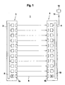
- FIG. 1 shows the structure of a light grid 1 for monitoring a monitoring area.
- the light grid 1 has a transmitter unit 3 integrated in a first housing 2 and a receiver unit 5 integrated in a second housing 4.
- the transmitter unit 3 has an array of transmitting light beams 6 emitting transmitters 7.
- the transmitters 7 are preferably made of identically formed light-emitting diodes and are arranged at a distance next to one another.
- the transmitters 7 are controlled by a transmitter control unit 8.
- the transmitter 7 are operated in pulsed mode.
- the transmitters 7 thus emit transmitted light pulses with a predetermined pulse-pause ratio.
- the individual transmitters 7 preferably emit cyclically successive transmitted light pulses, wherein the clocking takes place via the transmitter control unit 8.
- each transmitter 7 is preceded by a transmitting optics 7a.
- the transmission optics 7a are arranged in the region of the front wall of the housing 2 behind a not shown separately exit window.
- the receiver unit 5 has an array of identically formed receivers 9 arranged side by side.
- the receivers 9 preferably each consist of a photodiode and are arranged equidistantly.
- Each receiver 9 is preceded by a receiving optics 9a.
- a receiver 9 is located opposite a transmitter 7 of the transmitter unit 3, so that, when the beam path is free, the transmitted light beams 6 of a transmitter 7 strike the receiver 9 arranged opposite.
- the pending at the output of the receiver 9 received signals are evaluated in a central evaluation unit 10.
- the evaluation unit 10 also forms a receiver control unit for controlling the operation of the receiver 9.
- Each transmitting light beam 6 emitting transmitter 7 forms with the respectively associated, opposite receiver 9, a beam axis of the light grid.
- the transmitter 7 and the receiver 9 of the individual beam axes are cyclically activated one after the other.
- the received signals are evaluated in the evaluation unit 10 with a threshold value. If the level of the received signals of a receiver 9 is above the threshold value, a non-interrupted beam axis corresponding to a free beam path of the transmitted light beams 6 is present. If the level of the received signals of the receiver 9 is below the threshold value, there is an interrupted beam axis corresponding to an object engagement.
- a binary object detection signal is generated in the evaluation unit 10.
- a first switching state "object detected” forms an object message, that is to say an object was in the Monitored area. If no object is detected, the object detection signal assumes a second switching state "free surveillance area”.
- the light grid 1 is preferably used in the field of personal protection, with the light grid 1, a danger zone is monitored on a machine. If an object message is generated by an object detection in the monitoring area in the light grid 1, the machine is switched off in order to prevent any endangerment of persons by the machine. The object message thus forms a shutdown command for the machine. In contrast, the machine is put into operation when the object detection signal occupies the switching state "free surveillance area".
- a control signal can be read into the evaluation unit 10 via a line 11 connected to an input of the evaluation unit 10.
- the control signal can be generated as a function of an external sensor 12, which is shown schematically in FIG.
- the beam axes of the light grid 1 can be parameterized in different ways.
- different configurations of parameterizations of the beam axes are stored, which can be selectively activated with the read control signal. By reading such control signals into the light grid 1, its parameterization can be changed during its operation.
- different delay times are stored in the evaluation unit 10, which can also be activated by means of the control signals in order to be able to activate different configurations with the corresponding delay times.
- the standard operating mode is stored in the light grid 1, in which the interruption of any beam axis of the light grid 1 leads to the generation of an object message.
- a reduced resolution can be specified in the evaluation unit 10.
- the number N of successive beam axes which must be interrupted for the generation of an object message is stored as a parameter value.
- N 2
- two successive beam axes must therefore be interrupted in order to generate an object message. If only one beam axis is interrupted, no object message occurs. With this reduced resolution, the minimum size of objects that are to be detected with the light grid 1, can be specified.
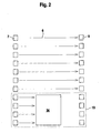
- FIG. 2 Such a blanking region 13 is shown schematically in FIG. 2, wherein it comprises the lowermost four beam axes of the light grid 1.
- FIG. 2 shows the case of a fixed blanking in which the blanking area 13 remains unchanged.
- the blanking area 13 can also be moved along the light grid 1.
- an object message is only carried out if at least one of the beam axes is interrupted outside the blanking area 13, regardless of whether or not a beam axis is interrupted within the blanking area 13.
- FIG. 2 shows in the light grid 1 with which the danger zone of a sawing machine is monitored.
- a Wooden plate 14 To edit a Wooden plate 14, this must be introduced into the surveillance area of the light grid 1 in the position shown in Figure 2.
- the insertion of the wooden plate 14 into the monitoring area of the light grid 1 is preferably monitored by the external sensor 12.
- This wooden plate 14 forms a non-safety-critical object.
- the beam axes of the light grid 1, which detect the wood panels 14, are defined as a blanking area 13.
- Figure 2 shows the wood panel 14 in its final position.
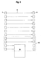
- FIG. 3 shows the arrangement according to FIG. 2 during the insertion of the wooden panel 14.
- a so-called monitored blanking area 13 can be deposited in the light grid 1.
- a non-safety-critical object is arranged within the blanking area 13, that is, whether the beam axes of the blanking area 13 are interrupted.
- an object message and thus a shutdown command for the monitored with the light grid 1 machine is not only generated when a safety-critical object enters the surveillance area and leads to the interruption of at least one beam axis outside the blanking area 13. Rather, a shutdown command is generated even if not all the beam axes of the blanking area 13 are interrupted.
- a specific time sequence of different blanking modes is preferably specified.
- an unmonitored blanking for the illustrated one is produced via the control signal Blanking area 13 activated.
- a delay time is defined via the or another control signal, for which the unmonitored blanking remains active. After the delay time has elapsed, a switchover to supervised blanking occurs automatically. The delay time is chosen so that at the switching time, the wooden plate 14 is completely inserted into the blanking area 13.
- unmonitored blanking is activated during the insertion process of the wood board 14 of FIG. 3, regardless of whether or not the beam axes of the blanking area 13 are interrupted, interruption of a beam axis outside the blanking area 13 results in a shutdown command for the saw machine. Since only a portion of the beam axes of the blanking area 13 is interrupted during the insertion of the wooden plate 14 into the blanking area 13, the mode of unmonitored blanking does not lead to an undesired shutdown of the sawing machine by the light grid 1.
- the switching takes place in the supervised blanking.
- the correct position of the wood panel 14 in the processing position is checked. If, for example, the wood panel 14 were not completely retracted into the processing position, so that not all of the beam axes of the blanking area 13 are interrupted, as shown in FIG. 2, a shutdown command for the sawing machine would be generated in the light grid 1.
- a corresponding time profile for specifying different blanking modes can be specified when the wood panel 14 is moved out of the machining position according to FIG. 2 via suitable control signals.
Landscapes
- Engineering & Computer Science (AREA)
- General Engineering & Computer Science (AREA)
- Physics & Mathematics (AREA)
- Life Sciences & Earth Sciences (AREA)
- General Life Sciences & Earth Sciences (AREA)
- General Physics & Mathematics (AREA)
- Geophysics (AREA)
- Mechanical Engineering (AREA)
- Geophysics And Detection Of Objects (AREA)
- Burglar Alarm Systems (AREA)
Applications Claiming Priority (1)
| Application Number | Priority Date | Filing Date | Title |
|---|---|---|---|
| DE102006012537A DE102006012537C5 (de) | 2006-03-18 | 2006-03-18 | Lichtgitter |
Publications (3)
| Publication Number | Publication Date |
|---|---|
| EP1835310A2 true EP1835310A2 (fr) | 2007-09-19 |
| EP1835310A3 EP1835310A3 (fr) | 2008-06-25 |
| EP1835310B1 EP1835310B1 (fr) | 2011-08-31 |
Family
ID=38110134
Family Applications (1)
| Application Number | Title | Priority Date | Filing Date |
|---|---|---|---|
| EP07004393A Not-in-force EP1835310B1 (fr) | 2006-03-18 | 2007-03-03 | Barrière lumineuse |
Country Status (3)
| Country | Link |
|---|---|
| EP (1) | EP1835310B1 (fr) |
| AT (1) | ATE522834T1 (fr) |
| DE (1) | DE102006012537C5 (fr) |
Cited By (9)
| Publication number | Priority date | Publication date | Assignee | Title |
|---|---|---|---|---|
| WO2010020433A1 (fr) * | 2008-08-22 | 2010-02-25 | Pepperl + Fuchs Gmbh | Procédé et capteur optique pour la détection d'objets |
| WO2010043430A1 (fr) * | 2008-10-14 | 2010-04-22 | Koenig & Bauer Aktiengesellschaft | Protection de zone de danger pour la zone de garnissage automatique sur un changeur de bobine |
| CN103033850A (zh) * | 2011-09-29 | 2013-04-10 | 克朗斯股份公司 | 触发光栅和用于测定容器位置的方法 |
| EP2933662A1 (fr) * | 2014-04-18 | 2015-10-21 | Omron Corporation | Capteur photo-électrique à axe multi-optique |
| EP2983013A1 (fr) * | 2014-08-08 | 2016-02-10 | Omron Corporation | Capteur photo-électrique à axe multi-optique et méthode de contrôle |
| AT517784A1 (de) * | 2015-10-01 | 2017-04-15 | Bernecker + Rainer Industrie-Elektronik Ges M B H | Verfahren zur automatisierten Steuerung einer Maschinenkomponente |
| CN111508121A (zh) * | 2020-03-30 | 2020-08-07 | 北京龙德时代技术服务有限公司 | 可视化多色激光智能虚拟闸机控制系统 |
| EP3770481A1 (fr) * | 2019-07-24 | 2021-01-27 | Leuze electronic GmbH + Co. KG | Dispositif capteur et procédés de surveillance de zone dangereuse |
| EP2274680B1 (fr) | 2008-05-09 | 2025-03-26 | Omron Scientific Technologies, INC. | Procédé et appareil pour la sélection de zone dans des dispositifs de surveillance de zone |
Families Citing this family (8)
| Publication number | Priority date | Publication date | Assignee | Title |
|---|---|---|---|---|
| DE102009031226B4 (de) * | 2009-07-01 | 2016-06-30 | Sick Ag | Sicherheitslichtgitter |
| DE102009056848B3 (de) * | 2009-12-03 | 2011-06-01 | Sick Ag | Verfahren zur Absicherung eines Gefahrenbereichs einer Maschine und zur Erkennung von Objekten |
| DE102011102232A1 (de) * | 2011-05-23 | 2012-11-29 | Marantec Antriebs- Und Steuerungstechnik Gmbh & Co. Kg | Lichtgitter |
| EP3217195B1 (fr) * | 2016-03-08 | 2023-04-26 | Leuze electronic GmbH + Co KG | Capteur optique |
| DE102016116828B4 (de) | 2016-09-08 | 2021-05-06 | Sick Ag | Sicherheitslichtvorhang |
| DE102018104313A1 (de) * | 2018-02-26 | 2019-08-29 | Marantec Antriebs- Und Steuerungstechnik Gmbh & Co. Kg | Verfahren zum Bestimmen der Torposition bei einer Toranlage |
| CN109581895B (zh) * | 2018-11-23 | 2020-08-25 | 华自科技股份有限公司 | 测试工装控制方法及装置、电子设备及存储介质 |
| DE202020102720U1 (de) | 2020-05-14 | 2022-10-31 | Leuze Electronic Gmbh + Co. Kg | Überwachungseinrichtung |
Citations (2)
| Publication number | Priority date | Publication date | Assignee | Title |
|---|---|---|---|---|
| DE10038025A1 (de) | 2000-08-02 | 2002-03-07 | Leuze Lumiflex Gmbh & Co | Vorrichtung und Verfahren zur Überwachung eines Gefahrenbereiches |
| DE20216230U1 (de) | 2002-10-22 | 2003-01-16 | Leuze lumiflex GmbH + Co., 82256 Fürstenfeldbruck | Lichtgitter |
Family Cites Families (7)
| Publication number | Priority date | Publication date | Assignee | Title |
|---|---|---|---|---|
| DE20104248U1 (de) * | 2001-03-12 | 2001-05-17 | Leuze lumiflex GmbH + Co., 80993 München | Lichtgitter |
| JP2003218679A (ja) * | 2002-01-25 | 2003-07-31 | Keyence Corp | 多光軸光電式安全装置 |
| DE10227710B4 (de) * | 2002-06-21 | 2006-04-27 | Leuze Lumiflex Gmbh + Co. Kg | Lichtgitter |
| DE10304054B4 (de) * | 2003-02-01 | 2005-03-03 | Leuze Lumiflex Gmbh + Co. Kg | Optischer Sensor |
| DE10341007B4 (de) * | 2003-09-05 | 2005-12-08 | Leuze Lumiflex Gmbh + Co. Kg | Lichtschrankenanordnung |
| DE10355008B4 (de) * | 2003-11-25 | 2007-01-11 | Leuze Lumiflex Gmbh + Co. Kg | Verfahren zur Verarbeitung eines Empfangssignals und optischer Sensor |
| DE102004022812B4 (de) * | 2004-05-08 | 2007-03-01 | Leuze Lumiflex Gmbh + Co. Kg | Verfahren zur Erfassung von Objekten in einem Überwachungsbereich mittels eines Lichtgitters |
-
2006
- 2006-03-18 DE DE102006012537A patent/DE102006012537C5/de not_active Expired - Fee Related
-
2007
- 2007-03-03 EP EP07004393A patent/EP1835310B1/fr not_active Not-in-force
- 2007-03-03 AT AT07004393T patent/ATE522834T1/de active
Patent Citations (2)
| Publication number | Priority date | Publication date | Assignee | Title |
|---|---|---|---|---|
| DE10038025A1 (de) | 2000-08-02 | 2002-03-07 | Leuze Lumiflex Gmbh & Co | Vorrichtung und Verfahren zur Überwachung eines Gefahrenbereiches |
| DE20216230U1 (de) | 2002-10-22 | 2003-01-16 | Leuze lumiflex GmbH + Co., 82256 Fürstenfeldbruck | Lichtgitter |
Cited By (20)
| Publication number | Priority date | Publication date | Assignee | Title |
|---|---|---|---|---|
| EP2274680B1 (fr) | 2008-05-09 | 2025-03-26 | Omron Scientific Technologies, INC. | Procédé et appareil pour la sélection de zone dans des dispositifs de surveillance de zone |
| WO2010020433A1 (fr) * | 2008-08-22 | 2010-02-25 | Pepperl + Fuchs Gmbh | Procédé et capteur optique pour la détection d'objets |
| EP2163917A1 (fr) | 2008-08-22 | 2010-03-17 | Pepperl + Fuchs GmbH | Procédé et capteur lumineux pour détéction de presence d'objets |
| WO2010043430A1 (fr) * | 2008-10-14 | 2010-04-22 | Koenig & Bauer Aktiengesellschaft | Protection de zone de danger pour la zone de garnissage automatique sur un changeur de bobine |
| US8339260B2 (en) | 2008-10-14 | 2012-12-25 | Koenig & Bauer Aktiengesellschaft | Securing a hazardous area in the regin surrounding the automatic loading of reels on a reel changer |
| CN103033850A (zh) * | 2011-09-29 | 2013-04-10 | 克朗斯股份公司 | 触发光栅和用于测定容器位置的方法 |
| EP2574964A3 (fr) * | 2011-09-29 | 2017-04-26 | Krones AG | Grille de lumière de déclenchement et procédé destiné à la détermination de la position de récipients |
| KR101630117B1 (ko) | 2014-04-18 | 2016-06-13 | 오므론 가부시키가이샤 | 다광축 광전 센서 |
| KR20150120848A (ko) * | 2014-04-18 | 2015-10-28 | 오므론 가부시키가이샤 | 다광축 광전 센서 |
| EP2933662B1 (fr) | 2014-04-18 | 2019-04-10 | Omron Corporation | Capteur photo-électrique à axe multi-optique |
| EP2933662A1 (fr) * | 2014-04-18 | 2015-10-21 | Omron Corporation | Capteur photo-électrique à axe multi-optique |
| CN105371094A (zh) * | 2014-08-08 | 2016-03-02 | 欧姆龙株式会社 | 多光轴光电传感器 |
| JP2016038318A (ja) * | 2014-08-08 | 2016-03-22 | オムロン株式会社 | 多光軸光電センサ |
| EP2983013A1 (fr) * | 2014-08-08 | 2016-02-10 | Omron Corporation | Capteur photo-électrique à axe multi-optique et méthode de contrôle |
| US9599748B2 (en) | 2014-08-08 | 2017-03-21 | Omron Corporation | Multi-optical axis photoelectric sensor |
| CN105371094B (zh) * | 2014-08-08 | 2018-06-26 | 欧姆龙株式会社 | 多光轴光电传感器 |
| AT517784A1 (de) * | 2015-10-01 | 2017-04-15 | Bernecker + Rainer Industrie-Elektronik Ges M B H | Verfahren zur automatisierten Steuerung einer Maschinenkomponente |
| AT517784B1 (de) * | 2015-10-01 | 2021-01-15 | B & R Ind Automation Gmbh | Verfahren zur automatisierten Steuerung einer Maschinenkomponente |
| EP3770481A1 (fr) * | 2019-07-24 | 2021-01-27 | Leuze electronic GmbH + Co. KG | Dispositif capteur et procédés de surveillance de zone dangereuse |
| CN111508121A (zh) * | 2020-03-30 | 2020-08-07 | 北京龙德时代技术服务有限公司 | 可视化多色激光智能虚拟闸机控制系统 |
Also Published As
| Publication number | Publication date |
|---|---|
| EP1835310A3 (fr) | 2008-06-25 |
| DE102006012537A1 (de) | 2007-09-20 |
| EP1835310B1 (fr) | 2011-08-31 |
| DE102006012537C5 (de) | 2011-11-17 |
| DE102006012537B4 (de) | 2008-10-16 |
| ATE522834T1 (de) | 2011-09-15 |
Similar Documents
| Publication | Publication Date | Title |
|---|---|---|
| EP1835310B1 (fr) | Barrière lumineuse | |
| EP2071363B1 (fr) | Barrière lumineuse et son procédé de fonctionnement | |
| EP1933174B1 (fr) | Barrière lumineuse | |
| EP1089030B1 (fr) | Procédé et dispositif de contrôle d'une zone de protection | |
| DE102012101369B4 (de) | Lichtvorhang | |
| DE102008050943B4 (de) | Optischer Sensor | |
| EP1494048B1 (fr) | Rideau de lumière | |
| EP2492714B1 (fr) | Procédé de fonctionnement d'une barrière lumineuse de sécurité et barrière lumineuse de sécurité | |
| DE10304054B4 (de) | Optischer Sensor | |
| EP1544643A1 (fr) | Procédé et dispositif pour la surveillance d'une zone avec plusieurs émetteurs de lumière disposés côte à côte | |
| DE10233258A1 (de) | Lichtgitter | |
| EP2012144B1 (fr) | Grille lumineuse et procédé destiné au fonctionnement d'une grille lumineuse | |
| EP2362242A1 (fr) | Capteur optoélectronique | |
| DE10341007A1 (de) | Lichtschrankenanordnung | |
| EP4191552A1 (fr) | Rideau lumineux | |
| EP1391752B1 (fr) | Grille de lumière | |
| EP3594553B1 (fr) | Dispositif de surveillance d'une zone de danger | |
| EP3244237B1 (fr) | Capteur optique et procédé d'opération d'un capteur optique | |
| DE10227710A1 (de) | Lichtgitter | |
| DE102005047776B4 (de) | Verfahren zum Betrieb eines Lichtgitters | |
| EP4092449B1 (fr) | Agencement de barrière lumineuse et procédé de détection des objets dans une zone de surveillance | |
| EP2259093B1 (fr) | Dispositif de capteur optoélectronique et procédé de fonctionnement d'un tel dispositif | |
| EP3869241B1 (fr) | Agencement de barrières lumineuses | |
| EP1480060A2 (fr) | Capteur optique | |
| DE20216230U1 (de) | Lichtgitter |
Legal Events
| Date | Code | Title | Description |
|---|---|---|---|
| PUAI | Public reference made under article 153(3) epc to a published international application that has entered the european phase |
Free format text: ORIGINAL CODE: 0009012 |
|
| AK | Designated contracting states |
Kind code of ref document: A2 Designated state(s): AT BE BG CH CY CZ DE DK EE ES FI FR GB GR HU IE IS IT LI LT LU LV MC MT NL PL PT RO SE SI SK TR |
|
| AX | Request for extension of the european patent |
Extension state: AL BA HR MK YU |
|
| PUAL | Search report despatched |
Free format text: ORIGINAL CODE: 0009013 |
|
| AK | Designated contracting states |
Kind code of ref document: A3 Designated state(s): AT BE BG CH CY CZ DE DK EE ES FI FR GB GR HU IE IS IT LI LT LU LV MC MT NL PL PT RO SE SI SK TR |
|
| AX | Request for extension of the european patent |
Extension state: AL BA HR MK RS |
|
| RIC1 | Information provided on ipc code assigned before grant |
Ipc: G01V 8/20 20060101AFI20070613BHEP Ipc: F16P 3/14 20060101ALI20080522BHEP |
|
| 17P | Request for examination filed |
Effective date: 20080703 |
|
| 17Q | First examination report despatched |
Effective date: 20080731 |
|
| AKX | Designation fees paid |
Designated state(s): AT BE BG CH CY CZ DE DK EE ES FI FR GB GR HU IE IS IT LI LT LU LV MC MT NL PL PT RO SE SI SK TR |
|
| GRAP | Despatch of communication of intention to grant a patent |
Free format text: ORIGINAL CODE: EPIDOSNIGR1 |
|
| RAP1 | Party data changed (applicant data changed or rights of an application transferred) |
Owner name: LEUZE ELECTRONIC GMBH + CO. KG |
|
| GRAS | Grant fee paid |
Free format text: ORIGINAL CODE: EPIDOSNIGR3 |
|
| GRAA | (expected) grant |
Free format text: ORIGINAL CODE: 0009210 |
|
| RBV | Designated contracting states (corrected) |
Designated state(s): AT CH DE LI |
|
| AK | Designated contracting states |
Kind code of ref document: B1 Designated state(s): AT CH DE LI |
|
| REG | Reference to a national code |
Ref country code: CH Ref legal event code: EP Ref country code: CH Ref legal event code: NV Representative=s name: ROTTMANN, ZIMMERMANN + PARTNER AG |
|
| REG | Reference to a national code |
Ref country code: CH Ref legal event code: PFA Owner name: LEUZE ELECTRONIC GMBH + CO. KG Free format text: LEUZE ELECTRONIC GMBH + CO. KG#IN DER BRAIKE 1#73277 OWEN/TECK (DE) -TRANSFER TO- LEUZE ELECTRONIC GMBH + CO. KG#IN DER BRAIKE 1#73277 OWEN/TECK (DE) |
|
| REG | Reference to a national code |
Ref country code: DE Ref legal event code: R096 Ref document number: 502007008006 Country of ref document: DE Effective date: 20111027 |
|
| PLBE | No opposition filed within time limit |
Free format text: ORIGINAL CODE: 0009261 |
|
| STAA | Information on the status of an ep patent application or granted ep patent |
Free format text: STATUS: NO OPPOSITION FILED WITHIN TIME LIMIT |
|
| 26N | No opposition filed |
Effective date: 20120601 |
|
| REG | Reference to a national code |
Ref country code: DE Ref legal event code: R097 Ref document number: 502007008006 Country of ref document: DE Effective date: 20120601 |
|
| PGFP | Annual fee paid to national office [announced via postgrant information from national office to epo] |
Ref country code: AT Payment date: 20140312 Year of fee payment: 8 |
|
| REG | Reference to a national code |
Ref country code: AT Ref legal event code: MM01 Ref document number: 522834 Country of ref document: AT Kind code of ref document: T Effective date: 20150303 |
|
| PG25 | Lapsed in a contracting state [announced via postgrant information from national office to epo] |
Ref country code: AT Free format text: LAPSE BECAUSE OF NON-PAYMENT OF DUE FEES Effective date: 20150303 |
|
| REG | Reference to a national code |
Ref country code: CH Ref legal event code: PCAR Free format text: NEW ADDRESS: GARTENSTRASSE 28 A, 5400 BADEN (CH) |
|
| PGFP | Annual fee paid to national office [announced via postgrant information from national office to epo] |
Ref country code: CH Payment date: 20210319 Year of fee payment: 15 |
|
| REG | Reference to a national code |
Ref country code: CH Ref legal event code: PL |
|
| PG25 | Lapsed in a contracting state [announced via postgrant information from national office to epo] |
Ref country code: LI Free format text: LAPSE BECAUSE OF NON-PAYMENT OF DUE FEES Effective date: 20220331 Ref country code: CH Free format text: LAPSE BECAUSE OF NON-PAYMENT OF DUE FEES Effective date: 20220331 |
|
| PGFP | Annual fee paid to national office [announced via postgrant information from national office to epo] |
Ref country code: DE Payment date: 20230308 Year of fee payment: 17 |
|
| REG | Reference to a national code |
Ref country code: DE Ref legal event code: R119 Ref document number: 502007008006 Country of ref document: DE |
|
| PG25 | Lapsed in a contracting state [announced via postgrant information from national office to epo] |
Ref country code: DE Free format text: LAPSE BECAUSE OF NON-PAYMENT OF DUE FEES Effective date: 20241001 |
|
| PG25 | Lapsed in a contracting state [announced via postgrant information from national office to epo] |
Ref country code: DE Free format text: LAPSE BECAUSE OF NON-PAYMENT OF DUE FEES Effective date: 20241001 |