EP1835521A1 - Support de contact mobile pour un mécanisme de disjoncteur - Google Patents
Support de contact mobile pour un mécanisme de disjoncteur Download PDFInfo
- Publication number
- EP1835521A1 EP1835521A1 EP06005463A EP06005463A EP1835521A1 EP 1835521 A1 EP1835521 A1 EP 1835521A1 EP 06005463 A EP06005463 A EP 06005463A EP 06005463 A EP06005463 A EP 06005463A EP 1835521 A1 EP1835521 A1 EP 1835521A1
- Authority
- EP
- European Patent Office
- Prior art keywords
- conductive
- circuit breaker
- contact
- contact carrier
- terminal
- Prior art date
- Legal status (The legal status is an assumption and is not a legal conclusion. Google has not performed a legal analysis and makes no representation as to the accuracy of the status listed.)
- Granted
Links
- 230000007246 mechanism Effects 0.000 title claims abstract description 46
- RYGMFSIKBFXOCR-UHFFFAOYSA-N Copper Chemical compound [Cu] RYGMFSIKBFXOCR-UHFFFAOYSA-N 0.000 claims description 9
- 229910052802 copper Inorganic materials 0.000 claims description 9
- 239000010949 copper Substances 0.000 claims description 9
- 238000010276 construction Methods 0.000 abstract description 2
- 239000004020 conductor Substances 0.000 description 3
- ATJFFYVFTNAWJD-UHFFFAOYSA-N Tin Chemical compound [Sn] ATJFFYVFTNAWJD-UHFFFAOYSA-N 0.000 description 2
- 230000009471 action Effects 0.000 description 2
- 230000008901 benefit Effects 0.000 description 2
- 230000000694 effects Effects 0.000 description 2
- 229910052709 silver Inorganic materials 0.000 description 2
- 239000004332 silver Substances 0.000 description 2
- 238000003466 welding Methods 0.000 description 2
- 229910001369 Brass Inorganic materials 0.000 description 1
- 229910000906 Bronze Inorganic materials 0.000 description 1
- 239000010951 brass Substances 0.000 description 1
- 239000010974 bronze Substances 0.000 description 1
- KUNSUQLRTQLHQQ-UHFFFAOYSA-N copper tin Chemical compound [Cu].[Sn] KUNSUQLRTQLHQQ-UHFFFAOYSA-N 0.000 description 1
- 230000008030 elimination Effects 0.000 description 1
- 238000003379 elimination reaction Methods 0.000 description 1
- 230000017525 heat dissipation Effects 0.000 description 1
- 230000006872 improvement Effects 0.000 description 1
- 239000000463 material Substances 0.000 description 1
- 238000000034 method Methods 0.000 description 1
- 229920003023 plastic Polymers 0.000 description 1
- 239000004033 plastic Substances 0.000 description 1
- 230000008569 process Effects 0.000 description 1
Images

Classifications
-
- H—ELECTRICITY
- H01—ELECTRIC ELEMENTS
- H01H—ELECTRIC SWITCHES; RELAYS; SELECTORS; EMERGENCY PROTECTIVE DEVICES
- H01H71/00—Details of the protective switches or relays covered by groups H01H73/00 - H01H83/00
- H01H71/02—Housings; Casings; Bases; Mountings
- H01H71/0207—Mounting or assembling the different parts of the circuit breaker
- H01H71/0221—Majority of parts mounted on central frame or wall
-
- H—ELECTRICITY
- H01—ELECTRIC ELEMENTS
- H01H—ELECTRIC SWITCHES; RELAYS; SELECTORS; EMERGENCY PROTECTIVE DEVICES
- H01H1/00—Contacts
- H01H1/12—Contacts characterised by the manner in which co-operating contacts engage
- H01H1/14—Contacts characterised by the manner in which co-operating contacts engage by abutting
- H01H1/22—Contacts characterised by the manner in which co-operating contacts engage by abutting with rigid pivoted member carrying the moving contact
Definitions
- This invention relates to a circuit breaker mechanism.
- the invention relates to the arrangement of a contact carrier forming part of the mechanism.
- the conduction path of a circuit breaker typically includes a line terminal and a load terminal, with a set of contacts and a load sensing device between the contacts.
- the set of contacts comprises a fixed contact and a moving contact, with the moving contact being mounted on a contact carrier which is supported pivotably on a frame member of the mechanism.
- the contact carrier is mounted pivotably to an operating handle which in turn is supported pivotably on a handle frame of the circuit breaker mechanism.
- the handle frame also serves as part of the conduction path of the mechanism.
- a flexible conductor known as a pig-tail, is welded to the moving contact carrier and to the handle frame and flexes with the movement of the contact carrier between a first position in which the contacts are closed and a second position in which the contacts are open.
- the flexible pig-tail is typically welded to the contact carrier and the handle frame.
- the welding process can cause distortion of the contact carrier, resulting in the contact carrier rubbing on the shell or housing of the circuit breaker, negatively affecting the switching action of the mechanism. It will also be appreciated that the stiffness, the orientation and the length of the flexible pig-tail have a direct effect on the contact pressure and other operating characteristics of the circuit breaker mechanism.
- a circuit breaker mechanism comprising a first terminal, a second terminal, a fixed contact connected to the first terminal, a conductive frame arranged to support an operating handle of the circuit breaker and connected electrically to the second terminal, and a moving contact assembly including a moving contact arranged to make contact with the fixed contact and a contact carrier supported pivotably on the conductive frame and connected both electrically and mechanically to said conductive frame only via a conductive pivot pin.
- the first terminal is a line terminal and the second terminal is a load terminal.
- the contact carrier preferably comprises a conductive member, the moving contact being supported at or near a first end of the conductive member and an opposed second end of the conductive member being shaped to engage at least one conductive pivot pin connected electrically to the conductive frame.
- the conductive member comprises a pair of generally parallel elongate limbs connected together, the moving contact being supported at or near a first end of the conductive member and the ends of the limbs at an opposed second end of the conductive member having recesses formed therein to engage respective conductive pivot pins connected electrically to the conductive frame.
- the mechanism may include a conductive bracket fixed to the conductive frame, the conductive bracket defining a pair of conductive pivot pins arranged to engage the respective ends of the limbs of the contact carrier.
- the conductive bracket preferably comprises copper.
- the conductive bracket may support a conductive handle pivot pin to which an operating handle of the mechanism is mounted, and which connects the conductive bracket electrically to the conductive frame.
- the conductive handle pivot pin is preferably formed from copper.
- the mechanism preferably includes at least one spring, which may be the main spring of the mechanism, arranged to urge the contact carrier of the moving contact assembly against said at least one conductive pivot pin.
- FIG. 1 shows a portion of an existing miniature circuit breaker mechanism manufactured by the applicant.
- a line terminal 10 defines a fixed contact 12 with an integral arc runner 14.
- a contact carrier 16 which carries a moving contact 18.
- Welded to the contact carrier 16 adjacent to the moving contact 18 is a first end 20 of a flexible conductor or pig-tail 22.
- the other end 24 of the pig-tail is welded to one end of a handle frame 26 that is preferably formed from copper.
- the handle frame supports an operating handle 28 of the circuit breaker mechanism on a pin 30.
- the lower end of the handle 28 defines a pair of opposed pins 32 and 34 having a part-circular profile, against which correspondingly shaped semicircular recesses 36 and 38 in the upper end of the contact carrier 16 bear pivotably.
- the electrical conduction path of the circuit breaker mechanism of Figure 1 is illustrated by the arrows from left to right in the Figure. It should be appreciated that the current path from the moving contact 18 to the handle frame 26 is entirely via the pig-tail 22.
- the handle 28 is typically formed from an insulating plastics material and there is thus no conduction path between the contact carrier 16 and the handle frame 26 via the handle 28.
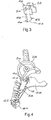
- circuit breaker mechanism of the invention is illustrated in Figure 2. Many of the components of the mechanism shown in Figure 2 are similar or identical to those in Figure 1 and therefore have the same reference numerals.
- the arrangement of the line terminal 10 and the fixed contact 12 are the same as in the mechanism of Figure 1.
- the contact carrier 16 is also unchanged, and essentially comprises a pair of generally parallel elongate limbs connected together. However, instead of engaging pins 32 and 34 defined by the handle 28, the recesses 36 and 38 at the upper end of the contact carrier bear against respective opposed pins 40 and 42 formed at the lower end 44 of a conductive bracket 46.
- the bracket 46 is fixed to the handle frame 26 and is in good electrical contact with it.
- the bracket 46 is generally U-shaped with a depending leg 48, the bearing/contact pins 40 and 42 being formed at the lower end 44 of the leg 48.
- the bracket 46 is preferably formed from copper of adequate hardness, plated with tin or silver, for example, to enhance its conductivity and provide suitable mechanical properties.
- the pins 40 and 42 can be formed integrally with the copper bracket, as shown, or could be brazed or otherwise fixed to the lower end of the bracket. In the latter case the pins could be formed of brass or bronze.
- the pins are preferably also plated with tin or silver.
- the pins 40 and 42 define smoothly curved bearing surfaces on which the recesses 36 and 38 at the upper end of the contact carrier 16 pivot.
- the bracket 46 has a pair of apertures 50 and 52 in opposed limbs of the U which are aligned with a corresponding aperture (not shown) in the handle frame 26 when the conductive bracket 46 is fixed to the handle frame.
- a copper handle pin 30 is fitted through the apertures 50 and 52, helping to ensure good electrical contact between the bracket 46 and the handle frame.
- the main spring 58 of the mechanism (shown schematically in Figure 4) is arranged to urge the contact carrier into firm engagement with the pins.
- An arc shield 60 is fitted to the lower end of the contact carrier 16 and has opposed transversely extending pins 62 which are received in respective notches 64 and 66 in the contact carrier.
- the main spring 58 extends between one pin 62 and one end 64 of a trip lever 66 forming part of the mechanism. The main spring 58 applies a sufficiently great component of force along the length of the contact carrier 16 to urge its upper end into firm contact with the pins 40 and 42, ensuring good electrical contact between the contact carrier and the pins.
- the main advantage of the described circuit breaker mechanism is that a consistent contact pressure can be maintained due to the absence of the pig-tail and any variations in the geometry of the contact carrier and other unwanted effects caused by the pig-tail.
- a softer main spring can be used as the variation in contact pressure and operating characteristics of the mechanism due to variations in the pig-tail characteristics is eliminated.
- the described mechanism has an improved switching action due to the fact that the movement of the moving contacts is not impeded by the pig-tail, resulting in higher contact closing/opening speeds, and also by the fact that deformation of the moving contact carrier due to welding is eliminated and thus the moving contact carrier does not tend to rub on the frame or shell of the circuit breaker. Similarly, "stickiness" of the operating handle is avoided.
- Another advantage is that the elimination of the pig-tail allows the line terminal to be reshaped to form a closer loop with the contact carrier, improving blow-off during short circuit conditions, with a potential improvement in short circuit performance.
- the arrangement also provides for additional space for levers operating an "in-line trip alarm/auxiliary switch" mechanism.
- construction is simplified due to the absence of the welded pig-tail, with a possible cost saving.
Landscapes
- Breakers (AREA)
- Push-Button Switches (AREA)
- Testing Of Individual Semiconductor Devices (AREA)
- Tests Of Electronic Circuits (AREA)
Priority Applications (3)
| Application Number | Priority Date | Filing Date | Title |
|---|---|---|---|
| EP06005463A EP1835521B1 (fr) | 2006-03-17 | 2006-03-17 | Support de contact mobile pour un mécanisme de disjoncteur |
| AT06005463T ATE434828T1 (de) | 2006-03-17 | 2006-03-17 | Bewegbare kontaktträgervorrichtung für einen schaltgerätmechanismus |
| DE602006007436T DE602006007436D1 (de) | 2006-03-17 | 2006-03-17 | Bewegbare Kontaktträgervorrichtung für einen Schaltgerätmechanismus |
Applications Claiming Priority (1)
| Application Number | Priority Date | Filing Date | Title |
|---|---|---|---|
| EP06005463A EP1835521B1 (fr) | 2006-03-17 | 2006-03-17 | Support de contact mobile pour un mécanisme de disjoncteur |
Publications (2)
| Publication Number | Publication Date |
|---|---|
| EP1835521A1 true EP1835521A1 (fr) | 2007-09-19 |
| EP1835521B1 EP1835521B1 (fr) | 2009-06-24 |
Family
ID=36691592
Family Applications (1)
| Application Number | Title | Priority Date | Filing Date |
|---|---|---|---|
| EP06005463A Expired - Lifetime EP1835521B1 (fr) | 2006-03-17 | 2006-03-17 | Support de contact mobile pour un mécanisme de disjoncteur |
Country Status (3)
| Country | Link |
|---|---|
| EP (1) | EP1835521B1 (fr) |
| AT (1) | ATE434828T1 (fr) |
| DE (1) | DE602006007436D1 (fr) |
Citations (4)
| Publication number | Priority date | Publication date | Assignee | Title |
|---|---|---|---|---|
| DE1068790B (fr) * | 1959-11-12 | |||
| US5189384A (en) * | 1991-11-06 | 1993-02-23 | Westinghouse Electric Corp. | Circuit breaker having improved contact structure |
| EP1126490A2 (fr) * | 2000-02-15 | 2001-08-22 | Eaton Corporation | Disjoncteur avec verrouillage et système de genouillère qui fonctionnent sur des plans différents |
| WO2002021556A1 (fr) * | 2000-09-05 | 2002-03-14 | Eaton Corporation | Interrupteur de circuit avec securisation accrue du mecanisme d'actionnement |
-
2006
- 2006-03-17 DE DE602006007436T patent/DE602006007436D1/de not_active Expired - Fee Related
- 2006-03-17 EP EP06005463A patent/EP1835521B1/fr not_active Expired - Lifetime
- 2006-03-17 AT AT06005463T patent/ATE434828T1/de not_active IP Right Cessation
Patent Citations (4)
| Publication number | Priority date | Publication date | Assignee | Title |
|---|---|---|---|---|
| DE1068790B (fr) * | 1959-11-12 | |||
| US5189384A (en) * | 1991-11-06 | 1993-02-23 | Westinghouse Electric Corp. | Circuit breaker having improved contact structure |
| EP1126490A2 (fr) * | 2000-02-15 | 2001-08-22 | Eaton Corporation | Disjoncteur avec verrouillage et système de genouillère qui fonctionnent sur des plans différents |
| WO2002021556A1 (fr) * | 2000-09-05 | 2002-03-14 | Eaton Corporation | Interrupteur de circuit avec securisation accrue du mecanisme d'actionnement |
Also Published As
| Publication number | Publication date |
|---|---|
| ATE434828T1 (de) | 2009-07-15 |
| EP1835521B1 (fr) | 2009-06-24 |
| DE602006007436D1 (de) | 2009-08-06 |
Similar Documents
| Publication | Publication Date | Title |
|---|---|---|
| US8049126B2 (en) | Self-adjusting plug-in line terminal | |
| US5694099A (en) | Switching devices | |
| CN101834102B (zh) | 电路断路器的过电流跳闸装置 | |
| US8115129B2 (en) | Switching device | |
| US5023416A (en) | Circuit breaker | |
| JP3794163B2 (ja) | 回路遮断器 | |
| US6879227B2 (en) | Switching contact arrangement | |
| EP0752155B1 (fr) | Ensemble a lame | |
| KR101579698B1 (ko) | 회로차단기 | |
| US7336146B2 (en) | Moving contact carrier arrangement for a circuit breaker mechanism | |
| EP1835521B1 (fr) | Support de contact mobile pour un mécanisme de disjoncteur | |
| KR101463043B1 (ko) | 회로차단기의 슬라이드형 가동접촉자 어셈블리 | |
| ZA200602105B (en) | Moving contact carrier arrangement for a circuit breaker mechanism | |
| JP3147181B2 (ja) | 回路遮断器の可動接触子装置 | |
| JP5093158B2 (ja) | 回路遮断器 | |
| JP7540415B2 (ja) | 回路遮断器 | |
| KR0170540B1 (ko) | 회로 차단기 | |
| JP4387075B2 (ja) | 回路遮断器 | |
| JP4440872B2 (ja) | 回路遮断器の可動接触装置 | |
| WO2009144150A1 (fr) | Bascule de contact | |
| KR101045470B1 (ko) | 회로 차단기 | |
| JP2583799B2 (ja) | 回路遮断器 | |
| JP2003123611A (ja) | 回路遮断器 | |
| JP2005347091A (ja) | 回路遮断器 | |
| JPH097488A (ja) | 配線用遮断器 |
Legal Events
| Date | Code | Title | Description |
|---|---|---|---|
| PUAI | Public reference made under article 153(3) epc to a published international application that has entered the european phase |
Free format text: ORIGINAL CODE: 0009012 |
|
| AK | Designated contracting states |
Kind code of ref document: A1 Designated state(s): AT BE BG CH CY CZ DE DK EE ES FI FR GB GR HU IE IS IT LI LT LU LV MC NL PL PT RO SE SI SK TR |
|
| AX | Request for extension of the european patent |
Extension state: AL BA HR MK YU |
|
| 17P | Request for examination filed |
Effective date: 20080207 |
|
| 17Q | First examination report despatched |
Effective date: 20080401 |
|
| AKX | Designation fees paid |
Designated state(s): AT BE BG CH CY CZ DE DK EE ES FI FR GB GR HU IE IS IT LI LT LU LV MC NL PL PT RO SE SI SK TR |
|
| GRAP | Despatch of communication of intention to grant a patent |
Free format text: ORIGINAL CODE: EPIDOSNIGR1 |
|
| GRAS | Grant fee paid |
Free format text: ORIGINAL CODE: EPIDOSNIGR3 |
|
| GRAA | (expected) grant |
Free format text: ORIGINAL CODE: 0009210 |
|
| AK | Designated contracting states |
Kind code of ref document: B1 Designated state(s): AT BE BG CH CY CZ DE DK EE ES FI FR GB GR HU IE IS IT LI LT LU LV MC NL PL PT RO SE SI SK TR |
|
| REG | Reference to a national code |
Ref country code: GB Ref legal event code: FG4D |
|
| REG | Reference to a national code |
Ref country code: CH Ref legal event code: EP |
|
| REG | Reference to a national code |
Ref country code: IE Ref legal event code: FG4D |
|
| REF | Corresponds to: |
Ref document number: 602006007436 Country of ref document: DE Date of ref document: 20090806 Kind code of ref document: P |
|
| PG25 | Lapsed in a contracting state [announced via postgrant information from national office to epo] |
Ref country code: LT Free format text: LAPSE BECAUSE OF FAILURE TO SUBMIT A TRANSLATION OF THE DESCRIPTION OR TO PAY THE FEE WITHIN THE PRESCRIBED TIME-LIMIT Effective date: 20090624 Ref country code: AT Free format text: LAPSE BECAUSE OF FAILURE TO SUBMIT A TRANSLATION OF THE DESCRIPTION OR TO PAY THE FEE WITHIN THE PRESCRIBED TIME-LIMIT Effective date: 20090624 Ref country code: FI Free format text: LAPSE BECAUSE OF FAILURE TO SUBMIT A TRANSLATION OF THE DESCRIPTION OR TO PAY THE FEE WITHIN THE PRESCRIBED TIME-LIMIT Effective date: 20090624 |
|
| PG25 | Lapsed in a contracting state [announced via postgrant information from national office to epo] |
Ref country code: SE Free format text: LAPSE BECAUSE OF FAILURE TO SUBMIT A TRANSLATION OF THE DESCRIPTION OR TO PAY THE FEE WITHIN THE PRESCRIBED TIME-LIMIT Effective date: 20090924 Ref country code: PL Free format text: LAPSE BECAUSE OF FAILURE TO SUBMIT A TRANSLATION OF THE DESCRIPTION OR TO PAY THE FEE WITHIN THE PRESCRIBED TIME-LIMIT Effective date: 20090624 Ref country code: LV Free format text: LAPSE BECAUSE OF FAILURE TO SUBMIT A TRANSLATION OF THE DESCRIPTION OR TO PAY THE FEE WITHIN THE PRESCRIBED TIME-LIMIT Effective date: 20090624 Ref country code: SI Free format text: LAPSE BECAUSE OF FAILURE TO SUBMIT A TRANSLATION OF THE DESCRIPTION OR TO PAY THE FEE WITHIN THE PRESCRIBED TIME-LIMIT Effective date: 20090624 |
|
| NLV1 | Nl: lapsed or annulled due to failure to fulfill the requirements of art. 29p and 29m of the patents act | ||
| PG25 | Lapsed in a contracting state [announced via postgrant information from national office to epo] |
Ref country code: EE Free format text: LAPSE BECAUSE OF FAILURE TO SUBMIT A TRANSLATION OF THE DESCRIPTION OR TO PAY THE FEE WITHIN THE PRESCRIBED TIME-LIMIT Effective date: 20090624 Ref country code: IS Free format text: LAPSE BECAUSE OF FAILURE TO SUBMIT A TRANSLATION OF THE DESCRIPTION OR TO PAY THE FEE WITHIN THE PRESCRIBED TIME-LIMIT Effective date: 20091024 Ref country code: CZ Free format text: LAPSE BECAUSE OF FAILURE TO SUBMIT A TRANSLATION OF THE DESCRIPTION OR TO PAY THE FEE WITHIN THE PRESCRIBED TIME-LIMIT Effective date: 20090624 Ref country code: ES Free format text: LAPSE BECAUSE OF FAILURE TO SUBMIT A TRANSLATION OF THE DESCRIPTION OR TO PAY THE FEE WITHIN THE PRESCRIBED TIME-LIMIT Effective date: 20091005 |
|
| PG25 | Lapsed in a contracting state [announced via postgrant information from national office to epo] |
Ref country code: SK Free format text: LAPSE BECAUSE OF FAILURE TO SUBMIT A TRANSLATION OF THE DESCRIPTION OR TO PAY THE FEE WITHIN THE PRESCRIBED TIME-LIMIT Effective date: 20090624 Ref country code: BE Free format text: LAPSE BECAUSE OF FAILURE TO SUBMIT A TRANSLATION OF THE DESCRIPTION OR TO PAY THE FEE WITHIN THE PRESCRIBED TIME-LIMIT Effective date: 20090624 Ref country code: NL Free format text: LAPSE BECAUSE OF FAILURE TO SUBMIT A TRANSLATION OF THE DESCRIPTION OR TO PAY THE FEE WITHIN THE PRESCRIBED TIME-LIMIT Effective date: 20090624 |
|
| PG25 | Lapsed in a contracting state [announced via postgrant information from national office to epo] |
Ref country code: PT Free format text: LAPSE BECAUSE OF FAILURE TO SUBMIT A TRANSLATION OF THE DESCRIPTION OR TO PAY THE FEE WITHIN THE PRESCRIBED TIME-LIMIT Effective date: 20091024 Ref country code: BG Free format text: LAPSE BECAUSE OF FAILURE TO SUBMIT A TRANSLATION OF THE DESCRIPTION OR TO PAY THE FEE WITHIN THE PRESCRIBED TIME-LIMIT Effective date: 20090924 |
|
| PG25 | Lapsed in a contracting state [announced via postgrant information from national office to epo] |
Ref country code: DK Free format text: LAPSE BECAUSE OF FAILURE TO SUBMIT A TRANSLATION OF THE DESCRIPTION OR TO PAY THE FEE WITHIN THE PRESCRIBED TIME-LIMIT Effective date: 20090624 |
|
| PLBE | No opposition filed within time limit |
Free format text: ORIGINAL CODE: 0009261 |
|
| STAA | Information on the status of an ep patent application or granted ep patent |
Free format text: STATUS: NO OPPOSITION FILED WITHIN TIME LIMIT |
|
| 26N | No opposition filed |
Effective date: 20100325 |
|
| PG25 | Lapsed in a contracting state [announced via postgrant information from national office to epo] |
Ref country code: MC Free format text: LAPSE BECAUSE OF NON-PAYMENT OF DUE FEES Effective date: 20100331 Ref country code: GR Free format text: LAPSE BECAUSE OF FAILURE TO SUBMIT A TRANSLATION OF THE DESCRIPTION OR TO PAY THE FEE WITHIN THE PRESCRIBED TIME-LIMIT Effective date: 20090925 |
|
| REG | Reference to a national code |
Ref country code: CH Ref legal event code: PL |
|
| GBPC | Gb: european patent ceased through non-payment of renewal fee |
Effective date: 20100317 |
|
| REG | Reference to a national code |
Ref country code: FR Ref legal event code: ST Effective date: 20101130 |
|
| PG25 | Lapsed in a contracting state [announced via postgrant information from national office to epo] |
Ref country code: IE Free format text: LAPSE BECAUSE OF NON-PAYMENT OF DUE FEES Effective date: 20100317 Ref country code: FR Free format text: LAPSE BECAUSE OF NON-PAYMENT OF DUE FEES Effective date: 20100331 |
|
| PG25 | Lapsed in a contracting state [announced via postgrant information from national office to epo] |
Ref country code: CH Free format text: LAPSE BECAUSE OF NON-PAYMENT OF DUE FEES Effective date: 20100331 Ref country code: LI Free format text: LAPSE BECAUSE OF NON-PAYMENT OF DUE FEES Effective date: 20100331 Ref country code: DE Free format text: LAPSE BECAUSE OF NON-PAYMENT OF DUE FEES Effective date: 20101001 |
|
| PG25 | Lapsed in a contracting state [announced via postgrant information from national office to epo] |
Ref country code: GB Free format text: LAPSE BECAUSE OF NON-PAYMENT OF DUE FEES Effective date: 20100317 Ref country code: IT Free format text: LAPSE BECAUSE OF FAILURE TO SUBMIT A TRANSLATION OF THE DESCRIPTION OR TO PAY THE FEE WITHIN THE PRESCRIBED TIME-LIMIT Effective date: 20090624 |
|
| PG25 | Lapsed in a contracting state [announced via postgrant information from national office to epo] |
Ref country code: CY Free format text: LAPSE BECAUSE OF FAILURE TO SUBMIT A TRANSLATION OF THE DESCRIPTION OR TO PAY THE FEE WITHIN THE PRESCRIBED TIME-LIMIT Effective date: 20090624 |
|
| PG25 | Lapsed in a contracting state [announced via postgrant information from national office to epo] |
Ref country code: HU Free format text: LAPSE BECAUSE OF FAILURE TO SUBMIT A TRANSLATION OF THE DESCRIPTION OR TO PAY THE FEE WITHIN THE PRESCRIBED TIME-LIMIT Effective date: 20091225 Ref country code: LU Free format text: LAPSE BECAUSE OF NON-PAYMENT OF DUE FEES Effective date: 20100317 |
|
| PG25 | Lapsed in a contracting state [announced via postgrant information from national office to epo] |
Ref country code: TR Free format text: LAPSE BECAUSE OF FAILURE TO SUBMIT A TRANSLATION OF THE DESCRIPTION OR TO PAY THE FEE WITHIN THE PRESCRIBED TIME-LIMIT Effective date: 20090624 |
|
| PG25 | Lapsed in a contracting state [announced via postgrant information from national office to epo] |
Ref country code: RO Free format text: LAPSE BECAUSE OF FAILURE TO SUBMIT A TRANSLATION OF THE DESCRIPTION OR TO PAY THE FEE WITHIN THE PRESCRIBED TIME-LIMIT Effective date: 20090624 |