EP1835547A1 - Module photovoltaique - Google Patents
Module photovoltaique Download PDFInfo
- Publication number
- EP1835547A1 EP1835547A1 EP04821428A EP04821428A EP1835547A1 EP 1835547 A1 EP1835547 A1 EP 1835547A1 EP 04821428 A EP04821428 A EP 04821428A EP 04821428 A EP04821428 A EP 04821428A EP 1835547 A1 EP1835547 A1 EP 1835547A1
- Authority
- EP
- European Patent Office
- Prior art keywords
- panel
- silicate glass
- lenses
- fresnel lenses
- photovoltaic module
- Prior art date
- Legal status (The legal status is an assumption and is not a legal conclusion. Google has not performed a legal analysis and makes no representation as to the accuracy of the status listed.)
- Granted
Links
Images


Classifications
-
- H—ELECTRICITY
- H10—SEMICONDUCTOR DEVICES; ELECTRIC SOLID-STATE DEVICES NOT OTHERWISE PROVIDED FOR
- H10F—INORGANIC SEMICONDUCTOR DEVICES SENSITIVE TO INFRARED RADIATION, LIGHT, ELECTROMAGNETIC RADIATION OF SHORTER WAVELENGTH OR CORPUSCULAR RADIATION
- H10F77/00—Constructional details of devices covered by this subclass
- H10F77/60—Arrangements for cooling, heating, ventilating or compensating for temperature fluctuations
- H10F77/63—Arrangements for cooling directly associated or integrated with photovoltaic cells, e.g. heat sinks directly associated with the photovoltaic cells or integrated Peltier elements for active cooling
-
- F—MECHANICAL ENGINEERING; LIGHTING; HEATING; WEAPONS; BLASTING
- F24—HEATING; RANGES; VENTILATING
- F24S—SOLAR HEAT COLLECTORS; SOLAR HEAT SYSTEMS
- F24S23/00—Arrangements for concentrating solar-rays for solar heat collectors
- F24S23/30—Arrangements for concentrating solar-rays for solar heat collectors with lenses
-
- H—ELECTRICITY
- H10—SEMICONDUCTOR DEVICES; ELECTRIC SOLID-STATE DEVICES NOT OTHERWISE PROVIDED FOR
- H10F—INORGANIC SEMICONDUCTOR DEVICES SENSITIVE TO INFRARED RADIATION, LIGHT, ELECTROMAGNETIC RADIATION OF SHORTER WAVELENGTH OR CORPUSCULAR RADIATION
- H10F77/00—Constructional details of devices covered by this subclass
- H10F77/40—Optical elements or arrangements
- H10F77/42—Optical elements or arrangements directly associated or integrated with photovoltaic cells, e.g. light-reflecting means or light-concentrating means
- H10F77/484—Refractive light-concentrating means, e.g. lenses
-
- Y—GENERAL TAGGING OF NEW TECHNOLOGICAL DEVELOPMENTS; GENERAL TAGGING OF CROSS-SECTIONAL TECHNOLOGIES SPANNING OVER SEVERAL SECTIONS OF THE IPC; TECHNICAL SUBJECTS COVERED BY FORMER USPC CROSS-REFERENCE ART COLLECTIONS [XRACs] AND DIGESTS
- Y02—TECHNOLOGIES OR APPLICATIONS FOR MITIGATION OR ADAPTATION AGAINST CLIMATE CHANGE
- Y02E—REDUCTION OF GREENHOUSE GAS [GHG] EMISSIONS, RELATED TO ENERGY GENERATION, TRANSMISSION OR DISTRIBUTION
- Y02E10/00—Energy generation through renewable energy sources
- Y02E10/40—Solar thermal energy, e.g. solar towers
-
- Y—GENERAL TAGGING OF NEW TECHNOLOGICAL DEVELOPMENTS; GENERAL TAGGING OF CROSS-SECTIONAL TECHNOLOGIES SPANNING OVER SEVERAL SECTIONS OF THE IPC; TECHNICAL SUBJECTS COVERED BY FORMER USPC CROSS-REFERENCE ART COLLECTIONS [XRACs] AND DIGESTS
- Y02—TECHNOLOGIES OR APPLICATIONS FOR MITIGATION OR ADAPTATION AGAINST CLIMATE CHANGE
- Y02E—REDUCTION OF GREENHOUSE GAS [GHG] EMISSIONS, RELATED TO ENERGY GENERATION, TRANSMISSION OR DISTRIBUTION
- Y02E10/00—Energy generation through renewable energy sources
- Y02E10/50—Photovoltaic [PV] energy
- Y02E10/52—PV systems with concentrators
Definitions
- the invention relates to the field of solar energy, in particular photovoltaic modules.
- the present invention can be used in land solar power plants with radiation concentrators designed for independent energy supply systems in different climatic zones.
- the module contains eight or sixteen Fresnel lenses and a corresponding quantity of solar cells, which are arranged opposite the lenses on an aluminum sheet, which at the same time takes on the role of a support for solar cells, a radiator and a metal housing.
- a support for solar cells a radiator
- a metal housing For electrical insulation of the solar cells on the housing plates of high-resistance silicon are used, which have a high thermal conductivity.
- the Fresnel lenses are made of an organic glass by pressing. To protect against atmospheric influences, the lenses are covered by a sheet of transparent film.
- the module exceeds on its technical and economic characteristics of the known silicon modules without concentrators, but the energy generated with it is very low.
- the closest analogue to the present invention is a photovoltaic module with solar concentrators, which is described in the documents of the international conference " CONFERENCE RECORD OF THE TWENTY-EIGHTTH IEEE PHOTOVOLTAIC SPECIALISTS CONFERENCE-2000 ", Ankorage, Alaska, USA, 2000, pp. 1169-1172 , was considered in detail.
- This module contains silicate gas sidewalls with a silica glass front panel fitted with Fresnel lenses on the upper edges and a silicate glass back panel with solar cells and a heat-dissipating base on the lower edges.
- the Fresnel lenses are made of silicone, have a square shape and are mounted close together and firmly connected to the inner surface of the glass, which fulfills a protective and carrier function.
- Each Fresnel lens is associated with its own solar cell, which is mounted on a heat-dissipating metal base.
- the heat-dissipating metal bases are arranged on the front glass side of the back panel so that the light-receiving surface of the solar cell is in the focal spot of the corresponding Fresnel lens.
- the heat-dissipating base also forms one of the electrical contacts of the solar cell.
- the second contact is formed by an upper metal layer of a laminated hard glass cloth and fixed on the heat-dissipating metal base, which is supplied with a wire contact with the attachment of its other end to a contact network of the solar cell.
- the switching of the solar cells is realized by contacts which are connected at the metal base to the upper metal layer of the hard glass fabric.
- the Fresnel lenses perpendicular to the sun's rays concentrate the sunlight and focus it on the light receiving surfaces of the solar cells.
- the solar cells convert the quantum energy of the light into electrical energy, producing a potential difference at their contacts.
- the electrical energy generated by the module is supplied to the outside of the user or an energy storage.
- the heat that is dissipated by the solar cells is distributed to the heat dissipating metal bases, transferred to the glass of the back panel and then discharged into the environment.
- the present module outperforms all other known photovoltaic modules with concentrators, including the analog described above, in terms of their characteristics.
- the present invention has for its object to develop a structure of the photovoltaic module in which the optical system is designed so that the increase in its power output is ensured.
- the object is achieved in that in a first embodiment of the photovoltaic module comprising side walls, a front panel made of silicate glass with Fresnel lenses on its rear side and a back panel made of silicate glass with solar cells and heat dissipating bases on its rear side, between said An additional intermediate board made of silicate glass is mounted on the front side flat convex lenses, which lie on the axis of the corresponding Fresnel lenses are arranged, wherein the distance of the intermediate board of the heat-dissipating bases more than the thickness of the solar cells but less than the size difference of Focal length of the flat convex lenses and the strength of the intermediate board.
- the photovoltaic module comprising side walls, a front panel of silicate glass with Fresnel lenses on the rear side and a back panel with solar cells and a heat dissipating means on the front side of the rear panel
- the heat dissipating means is formed as a metal plate and the back panel formed such that between her and the front panel, an additional intermediate panel made of silicate glass is mounted, arranged on the rear side flat convex lenses on an axis with the corresponding Fresnel lenses are, wherein the distance from the intermediate board to the surface of the heat dissipating plate is greater than the sum of the strengths of the solar cell and the flat convex lens and the focal length of the flat convex lenses is not exceeded.
- the heat dissipating means is formed as a metal plate and the back panel is formed in such a way that between it and the front panel an additional intermediate board of silicate glass with flat convex lenses is arranged on an axis with the corresponding Fresnel lenses, wherein the distance from the intermediate board to the surface of the heat dissipating plate greater than the thickness of the solar cell, but smaller than the size difference the focal length of the flat convex lenses and the strength of the intermediate board.
- the heat dissipating bases are formed as shells with a flat bottom, through the central , longitudinal lines of the surface optical axes of the respective Fresnel lenses run; these shells form a back panel, between which and the front panel an additional panel of silicate glass is arranged, on the rear side flat convex lenses are mounted on an axis with the corresponding Fresnel lenses, the shells dense by their tops with the rear surface of the intermediate panel and the distance from the intermediate panel to the rear surfaces of the flat tray bottoms is greater than the sum of the solar cell and flat convex lens powers but less than the focal length of the flat convex lenses.
- the side walls, a front panel of silica glass with Fresnel lenses on the rear side and a Back panel comprising solar cells and heat dissipating bases on the front side the heat dissipating bases are formed as shells with a flat bottom through whose central, longitudinal lines of the surfaces run optical axes of the corresponding Fresnel lenses forming an intermediate board, between the front panel and a additional intermediate board of silicate glass is arranged, on the front side of which the flat convex lenses are mounted on an axis with the corresponding Fresnel lenses, the shells being tightly connected by their tops to the rear surface of the intermediate board and the distance from the intermediate board to the surfaces the shallow tray bottoms is greater than the solar cell thickness but less than the difference in focal length of the flat convex lenses and the strength of the intermediate board.
- an additional solar concentrator makes it possible to increase the concentration factor maximally and to make the misorientation of the module wider (the deviation of the position of the photovoltaic module from the perpendicular of the sun's rays) or to improve energy-economic characteristics of the module by reducing the consumption of semiconductor materials in solar cells.
- Spatially separating the additional concentrator from the surface of the solar cell also makes it possible to reduce the density of solar radiation passing therethrough and thus reduce the radiation and temperature load on the additional concentrator, thereby improving the operating data of the photovoltaic module.
- openings are formed in the side, opposite walls of the photovoltaic module immediately above the additional intermediate panel and below the front panel for connection to the environment of the inner modulus space between these panels.
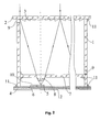
- the photovoltaic module contains side walls 1 made of silicate glass, on the upper edges of a front panel 2 made of silicate glass with Fresnel lenses 3 and on the lower edges of a back panel 4 made of silicate glass with solar cells 5 and heat-dissipating bases 6 are attached.
- the Fresnel lenses 3 are made of silicone, have a square shape, are arranged close to each other, and are fixedly connected to the inner surface of the glass, which fulfills a protective and carrier function.
- Each Fresnel lens 3 is associated with a solar cell 5 which is mounted on a heat-dissipating metal base 6.
- the heat-dissipating bases 6 are arranged on the front side of the glass of the back panel 4 so that the light-receiving surface of the solar cell 5 lies on the optical line of the corresponding Fresnel lens 3. Between the rear panel 4 and the front panel 2, an additional intermediate panel 7 made of silicate glass is arranged, on the surface of which flat convex silicone lenses 8 are mounted on an axis with the corresponding Fresnel lenses 3 and the solar cells 5. The distance from the intermediate board 7 to the heat dissipating bases 6 is greater than the thickness of the solar cells 5, but less than the size difference of the focal length of the flat convex lenses 8 and the thickness of the intermediate board 7.
- this distance is determined by the optical parameters of two Solar concentrators, the Fresnel lenses 3 and the flat convex lenses 8, determined by the conditions of optimal focusing of the optical system that the light-receiving surfaces of the solar cell 5 in the focal spot of two concentrators, the corresponding Fresnel lenses 3 and the flat convex lenses 8, lie.
- the flat convex lenses 8 are selected as short focus lenses; therefore, the distance from the surface of the intermediate panel 7 to the front surface of the back panel 4 is small compared to the distance between the front panel 2 and the intermediate panel 7.
- pass sleeves 9 are arranged immediately above the additional intermediate panel 7 and below the front panel 2, through the openings of which the inner modular space enclosed between the intermediate panel 7 and the front panel 2 is connected to the environment.
- the back panel 4 and this intermediate panel 7 close tightly closed to protect the solar cell 5 against environmental influences.
- the Fresnel lenses 3 and the flat convex lenses 8 made of silicone, which do not change their properties under the influence of moisture.
- the heat dissipating metal base 6 also forms one of the electrical contacts of the solar cell.
- the second contact is formed by an upper metal layer 10 covering a hard glass cloth mounted on the heat dissipating base 6 to which a wire contact (not shown in the figures) connected at its other end to the contact network of the solar cell 5 is connected ,
- the switching of the solar cells 5 is performed by contacts which are connected to the metal base 6 and the upper metal layer 10 of the hard glass fabric.
- the attachment of the side walls 1 to each other and to the panels 2, 4 and 7 is made by means of a sealing adhesive 11, whereby their firm connection with each other and the tightness of the inner module space between the back panel 4 and the intermediate panel 7 is ensured against the atmosphere, the protection the solar cell 5 is ensured against external factors.
- the photovoltaic module contains side walls 1 made of silicate glass, on the upper edges of which a front panel 2 of silicate glass with Fresnel lenses 3 and on the lower edges thereof a heat-dissipating metal plate 6 with solar cells 5 are fastened.
- the metal plate 6 forms a back panel of the photovoltaic module.
- the Fresnel lenses 3 are made of silicone and firmly bonded to the inner glass surface of the front panel 2. Each Fresnel lens 3 is associated with a solar cell 5 which is mounted on the heat-dissipating metal plate 6. The heat-dissipating metal plate 6 is arranged so that the light-receiving surfaces of the photocells 5 lie on the optical lines of the respective Fresnel lenses 3.
- an additional intermediate panel 7 made of silicate glass is arranged, on the rear surface of which flat-convex lenses 8 made of silicone are mounted on an axis with the corresponding Fresnel lenses 3 and the solar cells 5.
- the distance from the intermediate board 7 and the surface of the heat dissipating plate 6 is larger than the sum of the thickness of the solar cell 5 and the flat convex lens 8, but smaller than their focal length.
- the heat dissipating metal plate 6 forms one of the electrical contacts of the solar cell, as in the embodiment described above.
- the second contact is through an upper metal layer 10 of a laminated hard glass fabric formed on the heat-dissipating metal plate 6, to which a wire contact (not shown in the figures) is fed, whose other end is connected to the contact network of the solar cell 5.
- the switching of the solar cells 5 is performed by contacts which are fixed to the metal plate 6 and to the upper metal layer 10 of the hard glass fabric.
- This version of the module has the same advantages compared to the prototype as in the embodiment described above. In addition, this embodiment ensures a more efficient dissipation of the heat from the solar cells 5 through the metal plate into the environment unlike the first embodiment, in which the dissipation of heat through the glass plate of the back panel is realized.
- the photovoltaic module contains side walls 1 made of silicate glass, on whose upper edges a front panel 2 of silicate glass with Fresnel lenses 3 and on the lower edges thereof a heat-dissipating metal plate 6 with solar cells 5 are fastened.
- the metal plate 6 forms a back panel of the photovoltaic module.
- the Fresnel lenses 3 are made of silicone and firmly bonded to the inner glass surface of the front panel 2. Each Fresnel lens 3 corresponds to its own solar cell 5, which is mounted on a metal plate 6. The metal plate 6 is arranged so that the center of the light-receiving surfaces of the solar cells 5 lies on the optical axes of the respective Fresnel lenses 3.
- an additional intermediate panel 7 made of silicate glass is arranged, on the front surface flachkonvexe Silicone lenses 8 are arranged on an axis with the corresponding Fresnel lenses 3 and the solar cells 5.
- the distance from the intermediate board 7 to the heat dissipating metal plates 6 is larger than the thickness of the solar cells 5 and smaller than the size difference of the focal distance of the flat convex lenses 8 and the thickness of the intermediate board 7.
- the heat dissipating metal plate 6 forms an electrical contact of the solar cell as in the embodiment described above.
- the second contact is formed by an upper metal layer 10 of a laminated hard glass cloth mounted on the heat dissipating metal plate 6 to which a wire contact (not shown in Fig. 3) whose other end is connected to the contact network of the solar cell 5 is connected.
- the switching of the solar cells 5 is performed by contacts which are fixed to the metal plate 6 and the upper metal layer 10 of the hard glass fabric.
- a current and moisture-insulating layer 12 is applied on the rear side of the heat-dissipating metal plate 6, a current and moisture-insulating layer 12 is applied.
- the present embodiment of the module has the same advantages over the prototype as the second embodiment described above.
- the distance between this panel and the heat dissipating metal plate 6 becomes smaller at the same optical parameters of the additional concentrator (the flat convex lens 8). This increases the compactness of the module and the volume of the dense space between the heat dissipating metal plate 6 and the rear surface of the intermediate board 7, whereby mechanical stresses are further reduced with changes in the environmental temperature.
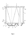
- the photovoltaic module includes side walls 1 made of silicate glass, on the upper edges of which a front panel 2 made of silicate glass with Fresnel lenses 3 and on the lower edges of which an intermediate panel 7 made of silicate glass are fixed. Underneath the rear surface, heat-dissipating bases 6 are attached as shells having a flat bottom. On the central, longitudinal lines of the shells solar cells 5 are fixed evenly. The shells are fastened with their bending edges by means of any known means to the rear glass surface of the intermediate panel 7, wherein the shells form a rear panel 4. On the rear surface of the intermediate panel 7, flat-convex silicone lenses 8 are mounted on an axis with the corresponding Fresnel lenses 3. The distance from the intermediate panel 7 to the surfaces of the flat bottoms of the shells is greater than the sum of the strengths of the solar cell and the flat convex lens and smaller than their focal length.
- pass sleeves 9 are provided directly above the additional intermediate panel 7 and below the front panel 2, through whose openings the module interior between the intermediate panel 7 and the front panel 2 is connected to the environment.
- the cumulative volume formed by the spaces between the rear surface of the intermediate panel 7 and the inner surface of the shells remains tight to protect the solar cells 5 from external influences.
- the heat dissipating metal bases (shells 6) form, as in all embodiments described above, one of the electrical contacts of the solar cell.
- the second contact is formed by an upper metal layer 10 of a laminated hard glass cloth on the heat dissipating base 6 to which a tape contact (not shown in FIG. 4) whose other end is connected to the contact network of the solar cell 5 is connected.
- these contacts will be for all Solar cells in a shell merged, ie, that the solar cells 5 are connected in parallel.
- Switching between the heat dissipating bases (shells 6) is done by metal contacts (not shown in FIG. 4), one pair of which is connected to each base 6.
- the present module design has the same advantages over the prototype as the embodiments described above.
- an additional advantage associated with the fact that the use of heat-dissipating bases (shells 6) with the group of connected solar cells allows to simplify the assembly of the photovoltaic modules and to use in their production automated, process engineering processes be widely used in optoelectronics.
- the photovoltaic module contains side walls 1 made of silicate glass, on the upper edges of which a front panel 2 of silicate glass with Fresnel lenses 3 and on the lower edges of which an intermediate panel 7 made of silicate glass is fixed.
- the heat dissipating bases 6 are mounted as shells with a flat bottom.
- longitudinal lines of the shells solar cells 5 are fixed evenly.
- the shells are fastened by their turn edges by means of any known means to the rear surface of the intermediate board 7 made of glass, forming a back panel 4.
- flat convex silicone lenses 8 are arranged on an axis with the corresponding Fresnel lenses 3.
- the distance from the intermediate board 7 to the heat dissipating bases 6 is larger than the thickness of the solar cell 5 and smaller than the size difference of the focal length of the flat convex lenses 8 and the thickness of the intermediate board 7.
- pass sleeves 9 are arranged directly above the additional intermediate panel 7 and below the front panel 2, through whose openings the interior space between the intermediate panel 7 and the front panel 2 is connected to the environment.
- a current and moisture insulating layer 12 is applied.
- This embodiment of the module has the same advantages over the prototype as the examples described above.
- the cumulative volume formed by the spaces between the rear surface of the intermediate panel 7 and the inner surface of the shells decreases due to the arrangement of the flat convex lenses 8 on the front surface of the intermediate panel 7 ,
- the Fresnel lenses 3 aligned perpendicular to the sun's rays concentrate the solar rays and focus them on the light-receiving surfaces of the solar cells 5.
- the solar cells 5 convert the quantum energy of the light into electrical energy, producing a potential difference between the contacts.
- the electrical energy produced by the module is fed to an external user or an energy store.
- the discharged from the solar cell 5 Heat is distributed in the heat-dissipating metal bases 6, supplied to the glass of the back panel 4 and then released into the environment.
- the other embodiments of the photovoltaic modules function identically to the first example. The only difference is that the heat from the heat dissipating bases (in the second and third embodiments, these are metal plates, in the fourth and fifth embodiments, these are shells) is released into the environment.
- photovoltaic modules according to the present invention are simple in their construction. They have high strength data, which ensure safe and long-term operation, are technically high in production and have high energy productivity and high technical-economic parameters.
Landscapes
- Engineering & Computer Science (AREA)
- Physics & Mathematics (AREA)
- Life Sciences & Earth Sciences (AREA)
- Sustainable Development (AREA)
- Sustainable Energy (AREA)
- Thermal Sciences (AREA)
- Chemical & Material Sciences (AREA)
- Combustion & Propulsion (AREA)
- Mechanical Engineering (AREA)
- General Engineering & Computer Science (AREA)
- Photovoltaic Devices (AREA)
- Hybrid Cells (AREA)
Applications Claiming Priority (2)
| Application Number | Priority Date | Filing Date | Title |
|---|---|---|---|
| RU2004131615/28A RU2307294C9 (ru) | 2004-11-01 | 2004-11-01 | Фотоэлектрический модуль (варианты) |
| PCT/RU2004/000429 WO2006049524A1 (fr) | 2004-11-01 | 2004-11-01 | Module photovoltaique |
Publications (3)
| Publication Number | Publication Date |
|---|---|
| EP1835547A1 true EP1835547A1 (fr) | 2007-09-19 |
| EP1835547A4 EP1835547A4 (fr) | 2009-03-18 |
| EP1835547B1 EP1835547B1 (fr) | 2011-08-24 |
Family
ID=36319440
Family Applications (1)
| Application Number | Title | Priority Date | Filing Date |
|---|---|---|---|
| EP04821428A Expired - Lifetime EP1835547B1 (fr) | 2004-11-01 | 2004-11-01 | Module photovoltaique |
Country Status (5)
| Country | Link |
|---|---|
| EP (1) | EP1835547B1 (fr) |
| AT (1) | ATE521992T1 (fr) |
| KZ (1) | KZ21493B (fr) |
| RU (1) | RU2307294C9 (fr) |
| WO (1) | WO2006049524A1 (fr) |
Cited By (15)
| Publication number | Priority date | Publication date | Assignee | Title |
|---|---|---|---|---|
| WO2009100894A3 (fr) * | 2008-02-13 | 2010-04-15 | Solartec Ag | Dispositif photovoltaïque, procédé de fabrication d'un dispositif photovoltaïque et installation solaire |
| WO2010012479A3 (fr) * | 2008-07-30 | 2010-10-07 | Fraunhofer-Gesellschaft zur Förderung der angewandten Forschung e.V. | Dispositif photovoltaïque, et procédé de fabrication d'une optique de concentrateur |
| WO2010137687A1 (fr) * | 2009-05-28 | 2010-12-02 | 京セラ株式会社 | Composant pour dispositif de conversion photoélectrique, dispositif de conversion photoélectrique et module de conversion photoélectrique |
| EP2323176A1 (fr) * | 2009-11-16 | 2011-05-18 | 'Telecom-STV' Company Limited | Module de concentrateur photoélectrique |
| WO2010091391A3 (fr) * | 2009-02-09 | 2011-09-29 | Semprius, Inc. | Modules photovoltaïques du type à concentrateur (cpv), récepteurs et sous-récepteurs et leurs procédés de formation |
| WO2011003903A3 (fr) * | 2009-07-08 | 2011-11-10 | Agc Glass Europe | Dispositif photovoltaïque à concentrateur à efficacité améliorée |
| WO2011034640A3 (fr) * | 2009-09-18 | 2011-11-17 | The Boeing Company | Concentrateur solaire fermé, hors axe |
| EP2286051A4 (fr) * | 2008-04-02 | 2012-05-02 | Morgan Solar Inc | Fenêtre à panneau solaire |
| WO2014037722A1 (fr) * | 2012-09-05 | 2014-03-13 | Fullsun Photovoltaics Limited | Module cellulaire photovoltaïque concentré (cpv) à élément optique secondaire, et procédé de fabrication |
| EP2590231A3 (fr) * | 2011-11-04 | 2014-05-07 | Most Energy Corporation | Lentille de condensation et système photovoltaïque l'utilisant |
| EP2139046A4 (fr) * | 2007-04-16 | 2014-09-24 | Zakrytoe Aktsionernoe Obschestvo Technoexan | Module photovoltaïque |
| US8940999B1 (en) | 2009-12-07 | 2015-01-27 | The Boeing Company | Modular off-axis solar concentrator |
| US9054251B1 (en) | 2011-07-28 | 2015-06-09 | The Boeing Company | Solar collector array |
| EP3236307A4 (fr) * | 2014-12-19 | 2018-09-26 | Esteves Palmeira, André Luiz | Concentrateur d'énergie solaire et électromagnétique |
| US10418501B2 (en) | 2015-10-02 | 2019-09-17 | X-Celeprint Limited | Wafer-integrated, ultra-low profile concentrated photovoltaics (CPV) for space applications |
Families Citing this family (18)
| Publication number | Priority date | Publication date | Assignee | Title |
|---|---|---|---|---|
| RU2354005C1 (ru) * | 2007-04-16 | 2009-04-27 | Закрытое акционерное общество "Техноэксан" | Фотоэлектрический модуль |
| RU2377696C1 (ru) * | 2008-09-09 | 2009-12-27 | Закрытое Акционерное Общество "ТЕЛЕКОМ-СТВ" | Концентраторный фотоэлектрический модуль |
| IL204034A (en) * | 2009-02-24 | 2015-05-31 | Schott Ag | Photovoltaic device with central optics |
| RU2411422C1 (ru) * | 2009-06-10 | 2011-02-10 | Российская академия сельскохозяйственных наук Государственное научное учреждение Всероссийский научно-исследовательский институт электрификации сельского хозяйства Российской академии сельскохозяйственных наук (ГНУ ВИЭСХ Россельхозакадемии) | Солнечный фотоэлектрический модуль |
| RU2395136C1 (ru) * | 2009-06-15 | 2010-07-20 | Учреждение Российской академии наук Физико-технический институт им. А.Ф. Иоффе РАН | Фотоэлектрический модуль |
| RU2444808C2 (ru) * | 2010-03-02 | 2012-03-10 | Российская академия сельскохозяйственных наук Государственное научное учреждение Всероссийский научно-исследовательский институт электрификации сельского хозяйства Российской академии сельскохозяйственных наук (ГНУ ВИЭСХ Россельхозакадемии) | Солнечный фотоэлектрический модуль с концентратором |
| RU2444809C2 (ru) * | 2010-06-10 | 2012-03-10 | Российская академия сельскохозяйственных наук Государственное научное учреждение Всероссийский научно-исследовательский институт электрификации сельского хозяйства Российской академии сельскохозяйственных наук (ГНУ ВИЭСХ Россельхозакадемии) | Солнечный фотоэлектрический модуль с концентратором |
| RU2436192C1 (ru) * | 2010-06-28 | 2011-12-10 | Российская Федерация, От Имени Которой Выступает Министерство Промышленности И Торговли Российской Федерации | Фотоэлектрический модуль с наноструктурным фотоэлементом |
| RU2442244C1 (ru) * | 2010-08-31 | 2012-02-10 | Учреждение Российской академии наук Физико-технический институт им. А.Ф. Иоффе РАН | Солнечный фотоэлектрический субмодуль |
| RU2436193C1 (ru) * | 2010-10-01 | 2011-12-10 | Учреждение Российской академии наук Физико-технический институт им. А.Ф. Иоффе РАН | Фотовольтаический концентраторный модуль |
| US20120318323A1 (en) * | 2011-02-14 | 2012-12-20 | Paul Anthony Tomaso | Ground mount ballast solar racking system |
| RU2496181C1 (ru) * | 2012-04-24 | 2013-10-20 | Федеральное государственное бюджетное учреждение науки Физико-технический институт им. А.Ф. Иоффе Российской академии наук | Фотоэлектрический концентраторный субмодуль |
| RU2578735C1 (ru) * | 2014-12-10 | 2016-03-27 | Федеральное государственное бюджетное учреждение науки Физико-технический институт им. А.Ф. Иоффе Российской академии наук | Концентраторный солнечный фотоэлектрический модуль |
| RU2611693C1 (ru) * | 2015-11-13 | 2017-02-28 | Федеральное государственное бюджетное учреждение науки Физико-технический институт им. А.Ф. Иоффе Российской академии наук | Солнечный концентраторный модуль |
| CN106094211A (zh) * | 2016-08-03 | 2016-11-09 | 杭州照相机械研究所 | 一种头戴式显示设备 |
| RU2641627C1 (ru) * | 2016-11-22 | 2018-01-18 | Федеральное государственное бюджетное учреждение науки Физико-технический институт им. А.Ф. Иоффе Российской академии наук | Солнечный фотоэлектрический концентраторный модуль |
| CA3048269C (fr) * | 2016-12-30 | 2021-06-15 | Bolymedia Holdings Co. Ltd. | Appareil solaire a concentration |
| RU2744355C1 (ru) * | 2020-08-04 | 2021-03-05 | Федеральное государственное бюджетное учреждение науки Физико-технический институт им. А.Ф. Иоффе Российской академии наук | Концентраторный фотоэлектрический модуль |
Family Cites Families (13)
| Publication number | Priority date | Publication date | Assignee | Title |
|---|---|---|---|---|
| US3985116A (en) * | 1974-04-22 | 1976-10-12 | Kaptron, Inc. | High efficiency solar panel |
| DE2924510A1 (de) * | 1979-06-18 | 1981-01-08 | Imchemie Kunststoff Gmbh | Konzentrator fuer solarzellen |
| JPS5848477A (ja) * | 1981-09-17 | 1983-03-22 | Nec Corp | 集光型太陽光発電装置 |
| US4830678A (en) * | 1987-06-01 | 1989-05-16 | Todorof William J | Liquid-cooled sealed enclosure for concentrator solar cell and secondary lens |
| US5123968A (en) * | 1989-04-17 | 1992-06-23 | The Boeing Company | Tandem photovoltaic solar cell with III-V diffused junction booster cell |
| US5091018A (en) | 1989-04-17 | 1992-02-25 | The Boeing Company | Tandem photovoltaic solar cell with III-V diffused junction booster cell |
| ES2081147T3 (es) * | 1992-03-13 | 1996-02-16 | Gerhard Feustle | Dispositivo para la concentracion o la distribucion de luz. |
| JPH07260261A (ja) * | 1994-03-22 | 1995-10-13 | Yazaki Corp | 太陽熱温水器 |
| US20040194820A1 (en) * | 2000-01-20 | 2004-10-07 | Steven Barone | Self tracking, wide angle solar concentrators |
| US6384320B1 (en) * | 2000-10-13 | 2002-05-07 | Leon Lung-Chen Chen | Solar compound concentrator of electric power generation system for residential homes |
| RU2194927C1 (ru) * | 2001-04-16 | 2002-12-20 | Исаев Пайзулла Исаевич | Солнечный коллектор |
| US6717045B2 (en) * | 2001-10-23 | 2004-04-06 | Leon L. C. Chen | Photovoltaic array module design for solar electric power generation systems |
| US7388146B2 (en) * | 2002-04-24 | 2008-06-17 | Jx Crystals Inc. | Planar solar concentrator power module |
-
2004
- 2004-11-01 WO PCT/RU2004/000429 patent/WO2006049524A1/fr not_active Ceased
- 2004-11-01 KZ KZ20072009A patent/KZ21493B/xx unknown
- 2004-11-01 AT AT04821428T patent/ATE521992T1/de active
- 2004-11-01 EP EP04821428A patent/EP1835547B1/fr not_active Expired - Lifetime
- 2004-11-01 RU RU2004131615/28A patent/RU2307294C9/ru not_active IP Right Cessation
Cited By (19)
| Publication number | Priority date | Publication date | Assignee | Title |
|---|---|---|---|---|
| EP2139046A4 (fr) * | 2007-04-16 | 2014-09-24 | Zakrytoe Aktsionernoe Obschestvo Technoexan | Module photovoltaïque |
| WO2009100894A3 (fr) * | 2008-02-13 | 2010-04-15 | Solartec Ag | Dispositif photovoltaïque, procédé de fabrication d'un dispositif photovoltaïque et installation solaire |
| EP2286051A4 (fr) * | 2008-04-02 | 2012-05-02 | Morgan Solar Inc | Fenêtre à panneau solaire |
| WO2010012479A3 (fr) * | 2008-07-30 | 2010-10-07 | Fraunhofer-Gesellschaft zur Förderung der angewandten Forschung e.V. | Dispositif photovoltaïque, et procédé de fabrication d'une optique de concentrateur |
| US8969716B2 (en) | 2008-07-30 | 2015-03-03 | Fraunhofer-Gesellschaft Zur Foerderung Der Angewandten Forschung E.V. | Photovoltaic device and method for producing a concentrator lens system |
| US10416425B2 (en) | 2009-02-09 | 2019-09-17 | X-Celeprint Limited | Concentrator-type photovoltaic (CPV) modules, receiver and sub-receivers and methods of forming same |
| WO2010091391A3 (fr) * | 2009-02-09 | 2011-09-29 | Semprius, Inc. | Modules photovoltaïques du type à concentrateur (cpv), récepteurs et sous-récepteurs et leurs procédés de formation |
| US8592673B2 (en) | 2009-05-04 | 2013-11-26 | The Boeing Company | Enclosed, off-axis solar concentrator |
| WO2010137687A1 (fr) * | 2009-05-28 | 2010-12-02 | 京セラ株式会社 | Composant pour dispositif de conversion photoélectrique, dispositif de conversion photoélectrique et module de conversion photoélectrique |
| WO2011003903A3 (fr) * | 2009-07-08 | 2011-11-10 | Agc Glass Europe | Dispositif photovoltaïque à concentrateur à efficacité améliorée |
| WO2011034640A3 (fr) * | 2009-09-18 | 2011-11-17 | The Boeing Company | Concentrateur solaire fermé, hors axe |
| EP2323176A1 (fr) * | 2009-11-16 | 2011-05-18 | 'Telecom-STV' Company Limited | Module de concentrateur photoélectrique |
| US8940999B1 (en) | 2009-12-07 | 2015-01-27 | The Boeing Company | Modular off-axis solar concentrator |
| US9660125B2 (en) | 2009-12-07 | 2017-05-23 | The Boeing Company | Method of making a modular off-axis solar concentrator |
| US9054251B1 (en) | 2011-07-28 | 2015-06-09 | The Boeing Company | Solar collector array |
| EP2590231A3 (fr) * | 2011-11-04 | 2014-05-07 | Most Energy Corporation | Lentille de condensation et système photovoltaïque l'utilisant |
| WO2014037722A1 (fr) * | 2012-09-05 | 2014-03-13 | Fullsun Photovoltaics Limited | Module cellulaire photovoltaïque concentré (cpv) à élément optique secondaire, et procédé de fabrication |
| EP3236307A4 (fr) * | 2014-12-19 | 2018-09-26 | Esteves Palmeira, André Luiz | Concentrateur d'énergie solaire et électromagnétique |
| US10418501B2 (en) | 2015-10-02 | 2019-09-17 | X-Celeprint Limited | Wafer-integrated, ultra-low profile concentrated photovoltaics (CPV) for space applications |
Also Published As
| Publication number | Publication date |
|---|---|
| RU2307294C9 (ru) | 2007-12-27 |
| WO2006049524A1 (fr) | 2006-05-11 |
| RU2307294C2 (ru) | 2007-09-27 |
| ATE521992T1 (de) | 2011-09-15 |
| EP1835547B1 (fr) | 2011-08-24 |
| KZ21493B (en) | 2009-07-15 |
| EP1835547A4 (fr) | 2009-03-18 |
Similar Documents
| Publication | Publication Date | Title |
|---|---|---|
| EP1835547B1 (fr) | Module photovoltaique | |
| DE60312358T2 (de) | Photovoltaisches modul mit einstellbarem kühlkörper und herstellungsverfahren | |
| EP2139046A1 (fr) | Module photovoltaïque | |
| DE102007052338A1 (de) | Photovoltaikanlage | |
| DE202011104880U1 (de) | Ein Solarzellenempfänger zur Verwendung in einem konzentrierten photovoltaischen System unter Verwendung von III-V Halbleitersolarzellen | |
| EP1891681A1 (fr) | Dispositif photovoltaique concentrateur, module concentrateur photovoltaique forme de ces dispositifs, ainsi que procede de production correspondant | |
| DE102005047132A1 (de) | Konzentrator-Photovoltaik-Vorrichtung; Photovoltaik-Einrichtung zur Verwendung darin sowie Herstellverfahren hierfür | |
| WO2007082517A2 (fr) | Dispositif photo voltaïque concentrateur doté d'un auxiliaire de positionnement | |
| DE102009004195A1 (de) | Solar-Modul in einem Isolierglasverbund und Verfahren zur Herstellung und Anwendung | |
| DE112006001229T5 (de) | Stationäres Photovoltaikmodul mit niedrigem Solarstrahlungs-Konzentrationsverhältnis | |
| DE102010004008A1 (de) | Solarzellenmodul und dessen Oberflächenschicht | |
| EP3231016A1 (fr) | Module photovoltaïque et système photovoltaïque | |
| DE102013220802A1 (de) | Solarmodul und Verfahren zum Herstellen eines Solarmoduls | |
| DE102008035735A1 (de) | Offenes verkapseltes Konzentratorsystem für Solarstrahlung | |
| DE102022123915A1 (de) | Photovoltaik-thermisches Modul | |
| DE102009056779A1 (de) | Photovoltaik-Modul | |
| DE102004001248B3 (de) | Stationärer photovoltaischer Sonnenlicht-Konzentrator | |
| DE112017001985T5 (de) | Photovoltaikanlage mit uneinheitlich gekühlten photovoltaikzellen | |
| EP1860706A1 (fr) | Élément thermo-solaire et photovoltaique en résine armée pour des revêtement de mur ou de toit | |
| DE29615560U1 (de) | Solarmodul bestehend aus der Kombination von Solarzellen der Photovoltaik und dem Kollektor (Absorber) von Solarthermikanlagen, sowie die Lichtzuführung über Spiegel | |
| DE20220390U1 (de) | Semi-statischer Konzentrator | |
| DE102010015848A1 (de) | Solarmodul oder Solarzelle mit optisch funktionaler witterungsbeständiger Oberflächenschicht | |
| DE102021123652A1 (de) | Tandem-Solarzelle | |
| DE202013003101U1 (de) | Photovoltaikvorrichtung | |
| DE10149620A1 (de) | Strom-Wärme-Solar-Kollektor |
Legal Events
| Date | Code | Title | Description |
|---|---|---|---|
| PUAI | Public reference made under article 153(3) epc to a published international application that has entered the european phase |
Free format text: ORIGINAL CODE: 0009012 |
|
| 17P | Request for examination filed |
Effective date: 20070601 |
|
| AK | Designated contracting states |
Kind code of ref document: A1 Designated state(s): AT BE BG CH CY CZ DE DK EE ES FI FR GB GR HU IE IS IT LI LU MC NL PL PT RO SE SI SK TR |
|
| RAP1 | Party data changed (applicant data changed or rights of an application transferred) |
Owner name: OOO,,RUSSKAJA SOLNENAJA KOMPANIJA'' |
|
| RIN1 | Information on inventor provided before grant (corrected) |
Inventor name: OOO,,RUSSKAJA SOLNENAJA KOMPANIJA'' |
|
| RIN1 | Information on inventor provided before grant (corrected) |
Inventor name: RUMANTSEV, VALERIY DMITRIEVICH Inventor name: CHALOV, ALESKSEY EVGENEVICH Inventor name: ZAZIMKO, VADIM NIKOLAEVICH Inventor name: SHAVARTS, MAKSIM SINOVEVICH Inventor name: IONOVA, EVGENIYA ALEKSANDROVNA Inventor name: ANDREEV, VYACHESLAV MIKHAYLOVICH Inventor name: ALFEROV, ZHORES IVANOVICH Inventor name: LOVYGIN, IGOR VLADIMIROVICH |
|
| DAX | Request for extension of the european patent (deleted) | ||
| RAP1 | Party data changed (applicant data changed or rights of an application transferred) |
Owner name: TECHNOEXAN LTD. |
|
| A4 | Supplementary search report drawn up and despatched |
Effective date: 20090218 |
|
| 17Q | First examination report despatched |
Effective date: 20090610 |
|
| GRAP | Despatch of communication of intention to grant a patent |
Free format text: ORIGINAL CODE: EPIDOSNIGR1 |
|
| GRAS | Grant fee paid |
Free format text: ORIGINAL CODE: EPIDOSNIGR3 |
|
| GRAA | (expected) grant |
Free format text: ORIGINAL CODE: 0009210 |
|
| AK | Designated contracting states |
Kind code of ref document: B1 Designated state(s): AT BE BG CH CY CZ DE DK EE ES FI FR GB GR HU IE IS IT LI LU MC NL PL PT RO SE SI SK TR |
|
| REG | Reference to a national code |
Ref country code: GB Ref legal event code: FG4D Free format text: NOT ENGLISH |
|
| REG | Reference to a national code |
Ref country code: CH Ref legal event code: EP |
|
| REG | Reference to a national code |
Ref country code: IE Ref legal event code: FG4D Free format text: LANGUAGE OF EP DOCUMENT: GERMAN |
|
| REG | Reference to a national code |
Ref country code: DE Ref legal event code: R082 Ref document number: 502004012827 Country of ref document: DE Representative=s name: JECK - FLECK - HERRMANN PATENTANWAELTE, DE Ref country code: DE Ref legal event code: R082 Ref document number: 502004012827 Country of ref document: DE Representative=s name: JECK - FLECK PATENTANWAELTE, DE |
|
| REG | Reference to a national code |
Ref country code: DE Ref legal event code: R096 Ref document number: 502004012827 Country of ref document: DE Effective date: 20111124 |
|
| REG | Reference to a national code |
Ref country code: NL Ref legal event code: VDEP Effective date: 20110824 |
|
| PG25 | Lapsed in a contracting state [announced via postgrant information from national office to epo] |
Ref country code: IS Free format text: LAPSE BECAUSE OF FAILURE TO SUBMIT A TRANSLATION OF THE DESCRIPTION OR TO PAY THE FEE WITHIN THE PRESCRIBED TIME-LIMIT Effective date: 20111224 Ref country code: SE Free format text: LAPSE BECAUSE OF FAILURE TO SUBMIT A TRANSLATION OF THE DESCRIPTION OR TO PAY THE FEE WITHIN THE PRESCRIBED TIME-LIMIT Effective date: 20110824 Ref country code: FI Free format text: LAPSE BECAUSE OF FAILURE TO SUBMIT A TRANSLATION OF THE DESCRIPTION OR TO PAY THE FEE WITHIN THE PRESCRIBED TIME-LIMIT Effective date: 20110824 Ref country code: PT Free format text: LAPSE BECAUSE OF FAILURE TO SUBMIT A TRANSLATION OF THE DESCRIPTION OR TO PAY THE FEE WITHIN THE PRESCRIBED TIME-LIMIT Effective date: 20111226 Ref country code: NL Free format text: LAPSE BECAUSE OF FAILURE TO SUBMIT A TRANSLATION OF THE DESCRIPTION OR TO PAY THE FEE WITHIN THE PRESCRIBED TIME-LIMIT Effective date: 20110824 |
|
| PG25 | Lapsed in a contracting state [announced via postgrant information from national office to epo] |
Ref country code: PL Free format text: LAPSE BECAUSE OF FAILURE TO SUBMIT A TRANSLATION OF THE DESCRIPTION OR TO PAY THE FEE WITHIN THE PRESCRIBED TIME-LIMIT Effective date: 20110824 Ref country code: CY Free format text: LAPSE BECAUSE OF FAILURE TO SUBMIT A TRANSLATION OF THE DESCRIPTION OR TO PAY THE FEE WITHIN THE PRESCRIBED TIME-LIMIT Effective date: 20110824 Ref country code: SI Free format text: LAPSE BECAUSE OF FAILURE TO SUBMIT A TRANSLATION OF THE DESCRIPTION OR TO PAY THE FEE WITHIN THE PRESCRIBED TIME-LIMIT Effective date: 20110824 Ref country code: GR Free format text: LAPSE BECAUSE OF FAILURE TO SUBMIT A TRANSLATION OF THE DESCRIPTION OR TO PAY THE FEE WITHIN THE PRESCRIBED TIME-LIMIT Effective date: 20111125 |
|
| REG | Reference to a national code |
Ref country code: IE Ref legal event code: FD4D |
|
| PG25 | Lapsed in a contracting state [announced via postgrant information from national office to epo] |
Ref country code: SK Free format text: LAPSE BECAUSE OF FAILURE TO SUBMIT A TRANSLATION OF THE DESCRIPTION OR TO PAY THE FEE WITHIN THE PRESCRIBED TIME-LIMIT Effective date: 20110824 Ref country code: IE Free format text: LAPSE BECAUSE OF FAILURE TO SUBMIT A TRANSLATION OF THE DESCRIPTION OR TO PAY THE FEE WITHIN THE PRESCRIBED TIME-LIMIT Effective date: 20110824 Ref country code: CZ Free format text: LAPSE BECAUSE OF FAILURE TO SUBMIT A TRANSLATION OF THE DESCRIPTION OR TO PAY THE FEE WITHIN THE PRESCRIBED TIME-LIMIT Effective date: 20110824 |
|
| BERE | Be: lapsed |
Owner name: TECHNOEXAN LTD. Effective date: 20111130 |
|
| PG25 | Lapsed in a contracting state [announced via postgrant information from national office to epo] |
Ref country code: IT Free format text: LAPSE BECAUSE OF FAILURE TO SUBMIT A TRANSLATION OF THE DESCRIPTION OR TO PAY THE FEE WITHIN THE PRESCRIBED TIME-LIMIT Effective date: 20110824 Ref country code: EE Free format text: LAPSE BECAUSE OF FAILURE TO SUBMIT A TRANSLATION OF THE DESCRIPTION OR TO PAY THE FEE WITHIN THE PRESCRIBED TIME-LIMIT Effective date: 20110824 Ref country code: RO Free format text: LAPSE BECAUSE OF FAILURE TO SUBMIT A TRANSLATION OF THE DESCRIPTION OR TO PAY THE FEE WITHIN THE PRESCRIBED TIME-LIMIT Effective date: 20110824 |
|
| PG25 | Lapsed in a contracting state [announced via postgrant information from national office to epo] |
Ref country code: DK Free format text: LAPSE BECAUSE OF FAILURE TO SUBMIT A TRANSLATION OF THE DESCRIPTION OR TO PAY THE FEE WITHIN THE PRESCRIBED TIME-LIMIT Effective date: 20110824 Ref country code: MC Free format text: LAPSE BECAUSE OF NON-PAYMENT OF DUE FEES Effective date: 20111130 |
|
| PLBE | No opposition filed within time limit |
Free format text: ORIGINAL CODE: 0009261 |
|
| REG | Reference to a national code |
Ref country code: CH Ref legal event code: PL |
|
| STAA | Information on the status of an ep patent application or granted ep patent |
Free format text: STATUS: NO OPPOSITION FILED WITHIN TIME LIMIT |
|
| GBPC | Gb: european patent ceased through non-payment of renewal fee |
Effective date: 20111124 |
|
| PG25 | Lapsed in a contracting state [announced via postgrant information from national office to epo] |
Ref country code: CH Free format text: LAPSE BECAUSE OF NON-PAYMENT OF DUE FEES Effective date: 20111130 Ref country code: LI Free format text: LAPSE BECAUSE OF NON-PAYMENT OF DUE FEES Effective date: 20111130 |
|
| 26N | No opposition filed |
Effective date: 20120525 |
|
| PG25 | Lapsed in a contracting state [announced via postgrant information from national office to epo] |
Ref country code: BE Free format text: LAPSE BECAUSE OF NON-PAYMENT OF DUE FEES Effective date: 20111130 |
|
| REG | Reference to a national code |
Ref country code: DE Ref legal event code: R097 Ref document number: 502004012827 Country of ref document: DE Effective date: 20120525 |
|
| PG25 | Lapsed in a contracting state [announced via postgrant information from national office to epo] |
Ref country code: GB Free format text: LAPSE BECAUSE OF NON-PAYMENT OF DUE FEES Effective date: 20111124 |
|
| REG | Reference to a national code |
Ref country code: AT Ref legal event code: MM01 Ref document number: 521992 Country of ref document: AT Kind code of ref document: T Effective date: 20111101 |
|
| PG25 | Lapsed in a contracting state [announced via postgrant information from national office to epo] |
Ref country code: AT Free format text: LAPSE BECAUSE OF NON-PAYMENT OF DUE FEES Effective date: 20111101 |
|
| PG25 | Lapsed in a contracting state [announced via postgrant information from national office to epo] |
Ref country code: ES Free format text: LAPSE BECAUSE OF FAILURE TO SUBMIT A TRANSLATION OF THE DESCRIPTION OR TO PAY THE FEE WITHIN THE PRESCRIBED TIME-LIMIT Effective date: 20111205 |
|
| PG25 | Lapsed in a contracting state [announced via postgrant information from national office to epo] |
Ref country code: LU Free format text: LAPSE BECAUSE OF NON-PAYMENT OF DUE FEES Effective date: 20111101 |
|
| PG25 | Lapsed in a contracting state [announced via postgrant information from national office to epo] |
Ref country code: BG Free format text: LAPSE BECAUSE OF FAILURE TO SUBMIT A TRANSLATION OF THE DESCRIPTION OR TO PAY THE FEE WITHIN THE PRESCRIBED TIME-LIMIT Effective date: 20111124 |
|
| PG25 | Lapsed in a contracting state [announced via postgrant information from national office to epo] |
Ref country code: TR Free format text: LAPSE BECAUSE OF FAILURE TO SUBMIT A TRANSLATION OF THE DESCRIPTION OR TO PAY THE FEE WITHIN THE PRESCRIBED TIME-LIMIT Effective date: 20110824 |
|
| PG25 | Lapsed in a contracting state [announced via postgrant information from national office to epo] |
Ref country code: HU Free format text: LAPSE BECAUSE OF FAILURE TO SUBMIT A TRANSLATION OF THE DESCRIPTION OR TO PAY THE FEE WITHIN THE PRESCRIBED TIME-LIMIT Effective date: 20110824 |
|
| REG | Reference to a national code |
Ref country code: FR Ref legal event code: PLFP Year of fee payment: 12 |
|
| PGFP | Annual fee paid to national office [announced via postgrant information from national office to epo] |
Ref country code: DE Payment date: 20151119 Year of fee payment: 12 |
|
| PGFP | Annual fee paid to national office [announced via postgrant information from national office to epo] |
Ref country code: FR Payment date: 20151119 Year of fee payment: 12 |
|
| REG | Reference to a national code |
Ref country code: DE Ref legal event code: R119 Ref document number: 502004012827 Country of ref document: DE |
|
| REG | Reference to a national code |
Ref country code: FR Ref legal event code: ST Effective date: 20170731 |
|
| PG25 | Lapsed in a contracting state [announced via postgrant information from national office to epo] |
Ref country code: FR Free format text: LAPSE BECAUSE OF NON-PAYMENT OF DUE FEES Effective date: 20161130 |
|
| PG25 | Lapsed in a contracting state [announced via postgrant information from national office to epo] |
Ref country code: DE Free format text: LAPSE BECAUSE OF NON-PAYMENT OF DUE FEES Effective date: 20170601 |