EP1835602A2 - Actionneur magnétique en mouvement avec collier d'ensouple à denture et course d'armature asymétrique - Google Patents
Actionneur magnétique en mouvement avec collier d'ensouple à denture et course d'armature asymétrique Download PDFInfo
- Publication number
- EP1835602A2 EP1835602A2 EP07405072A EP07405072A EP1835602A2 EP 1835602 A2 EP1835602 A2 EP 1835602A2 EP 07405072 A EP07405072 A EP 07405072A EP 07405072 A EP07405072 A EP 07405072A EP 1835602 A2 EP1835602 A2 EP 1835602A2
- Authority
- EP
- European Patent Office
- Prior art keywords
- actuator
- armature
- force
- endplate
- ring
- Prior art date
- Legal status (The legal status is an assumption and is not a legal conclusion. Google has not performed a legal analysis and makes no representation as to the accuracy of the status listed.)
- Granted
Links
Images

Classifications
-
- H—ELECTRICITY
- H01—ELECTRIC ELEMENTS
- H01F—MAGNETS; INDUCTANCES; TRANSFORMERS; SELECTION OF MATERIALS FOR THEIR MAGNETIC PROPERTIES
- H01F7/00—Magnets
- H01F7/06—Electromagnets; Actuators including electromagnets
- H01F7/08—Electromagnets; Actuators including electromagnets with armatures
- H01F7/16—Rectilinearly-movable armatures
- H01F7/1607—Armatures entering the winding
- H01F7/1615—Armatures or stationary parts of magnetic circuit having permanent magnet
-
- H—ELECTRICITY
- H02—GENERATION; CONVERSION OR DISTRIBUTION OF ELECTRIC POWER
- H02K—DYNAMO-ELECTRIC MACHINES
- H02K33/00—Motors with reciprocating, oscillating or vibrating magnet, armature or coil system
- H02K33/16—Motors with reciprocating, oscillating or vibrating magnet, armature or coil system with polarised armatures moving in alternate directions by reversal or energisation of a single coil system
Definitions
- the present invention relates to a moving magnet actuator (MMA) in accordance with the preamble of claim1.
- Moving magnet actuators generally comprise an armature containing a sintered, anisotropic, axially-oriented, permanent ring magnet sandwiched between two magnetically conductive pole end pieces that are affixed to a non-conductive shaft.
- an electromotive force is imparted on the permanent magnet such as by two in-series, oppositely wound, coils located in a radial air gap between the outer diameter of the magnetically conductive pole pieces and the inner diameter of a magnetically conductive conduit that encloses the MMA components
- the shaft will be caused to move axially in a positive or negative direction.
- the shaft typically extends outside the magnetic conduit and is used to unseat or seat a value or operate as a switch.
- Such MMAs are commonly used in a number of industrial applications. For example, MMAs are often used to control the fuel feed rate for a diesel engine. Other applications include, but are not limited to liquid heat generators.
- the above-described conventional construction of an MMA results in a magnetic circuit that produces an attractive force from one coil or winding and a repelling force by the other coil or winding.
- the coils operate in the same direction thereby accelerating the armature in either the positive or negative directions, depending upon the polarity of the windings.
- Magnetic flux lines circulating from the magnetically conductive conduit across one winding through the magnetically conductive pole piece (endplate) through the magnet to the other magnetically conductive pole piece (endplate) and across the other winding back to the magnetically conductive conduit produce the electromotive force that causes translation of the armature relative to the magnetic conduit.
- the MMA armature has a range of travel or stroke that is symmetrical about a radially-orientated centerline that is perpendicular to the central axis of the actuator.
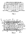
- MMA's typically operate according to a force versus position curve that has an umbrella-like shape, such as that illustrated in Fig. 1.
- the greatest magnitude of electromotive force 10 is found in the central portion of the actuator's range of motion, which is defined along the x-axis in inches. Force is defined in pounds along the y-axis.
- This actuator's range of motion is generally referred to as the actuator's stroke and, as shown in Fig. 1, for most MMA's, more electromotive force is present at the center of the actuator's stroke than at the beginning 12 or the end 14.
- This conventional MMA construction produces a "cogging" effect as a result of the armature wanting to center itself relative to the boundaries of the magnetically conductive conduit within which it travels.
- This cogging effect or force is increasingly additive to the electromagnetic force acting on the armature when the MMA is powered. This additive force reaches a maximum at the radial center of the magnetically conductive conduit.
- the cogging force is subtractive to the electromagnetic force acting on the armature.
- the cogging force pulls the armature back to the radial center. This subtractive effect is particularly undesirable.
- the subtractive force placed on the armature affects the response time of the armature. That is, when the MMA is powered, the armature will translate axially within the conductive conduit it sits. Typically, for the armature to translate from its rest to its fully translated position, the force exerted on the armature by a biasing spring must be overcome. If the spring bias is not overcome, the armature will not reach its fully translated position. Moreover, the armature will reciprocate within the conduit as it "hunts" for a position of equilibrium. In other words, the armature will push against the spring and the spring will push back. The aforementioned cogging effect increases the force necessary to compress the spring.
- the armature must compress the spring and overcome the cogging forces placed thereon to reach a fully translated position. It therefore follows that if the cogging force can be reduced or at least countered, the armature must only overcome the k-factor of the spring when going from an initial to a fully translated (open) position. Accordingly, the work needed to translate the armature is increased by the cogging force.
- a spring with a reduced k-factor must be used to account for the cogging force.
- the force of the spring on the armature and the cogging force are additive.
- a spring with an increased k-factor could be used or the amount of work needed to move the armature could be reduced.
- the spring improves the response time of the MMA when the MMA goes from a powered to an un-powered state.
- a spring with greater spring-back characteristics quickly returns the armature to its rest position when the electromotive force is removed.
- the present invention is directed to an MMA that overcomes the aforementioned drawbacks.
- the MMA is constructed to include a magnetically conductive end-ring that is spaced from a magnet pole piece.
- the end-ring is constructed and spaced to provide a desired counter or anti-cogging force when the MMA is in a powered state.
- the MMA is also preferably constructed to have an asymmetrical armature stroke.
- an actuator having a magnetic conduit and an armature that moves linearly within the magnetic conduit when an electromotive force is placed thereon.
- the actuator further has a magnetically conductive endplate connected to an end of the magnetic conduit and spaced from the armature.
- the magnetically conductive endplate places a mitigating force on the armature at least equal to a cogging force acting on the permanent magnet when the armature is in close proximity to a radially-oriented centerline of the magnetic conduit that is perpendicular to a central axis of the armature.
- the invention includes an actuator having a ring-shaped, movable magnet and a non-conductive shaft extending through an inner diameter of the movable magnet.
- the actuator is constructed to also have a ring-shaped endplate spaced from but magnetically coupled to the movable magnet.
- the endplate has an inner diameter that together with a gap defined between the endplate and the movable magnet place an attractive force on the movable magnet at least equal to a cogging force placed on the movable magnet.
- the invention is directed to an actuator having a magnetic circuit defined by a conduit, an end-ring, a first pole endplate spaced axially from the end-ring, a magnet, a second pole endplate, and the conduit.
- the magnetic circuit imparts a cogging force on the magnet when the magnet is disposed in close proximity to a center region of the conduit and imparts a counter-cogging force on the magnet by the end-ring when the magnet moves away from the center region of the conduit.
- the invention includes an actuator comprising a magnetically conductive conduit having a radial centerline.
- the actuator is also constructed to include an armature movable along an axis perpendicular to the radial centerline.
- the armature has a linear range of motion within the conduit that defines an armature stroke.
- the center of the armature stroke is offset from the radial centerline of the magnetically conductive conduit.
- the invention in embodied in an actuator having means for providing a cogging force when an armature is at or near a center region of a magnetically conductive conduit in which it travels.
- the actuator further includes means for negating the cogging force when the armature is linearly displaced from the center region.
- Fig. 1 is a graph illustrating a force vs. position curve for a known MMA.
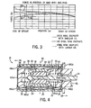
- Fig. 2 is a cross-sectional view of an MMA with a counter-cogging end-ring in accordance with one aspect of the invention.
- Fig. 3 is a graph illustrating two force vs. position curves for exemplary MMAs, constructed in accordance with the present invention, relative to the force vs. position curve of Fig. 1.
- Fig. 4 is a cross-sectional view of a bi-directional MMA with a pair of counter-cogging end-rings in accordance with another aspect of the invention.
- Fig. 5 is a graph illustrating force vs. position curves for the bi-directional MMA shown in Fig. 4.
- Fig. 6 is a cross-sectional view of another MMA with a counter-cogging end-ring and asymmetrical offset region of armature stroke in accordance with yet another aspect of the invention.
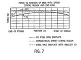
- Fig. 7 is a graph illustrating force vs. position curves for (a) conventional MMA, (b) the MMA shown in Fig. 2, and (c) the MMA shown in Fig. 6.
- a MMA according to one embodiment of the invention is shown in cross-section in Fig. 2.
- the MMA is constructed to exert a counter or anti-cogging force.
- the MMA 16 is similar to conventional MMA design in that an armature 17 is designed to have a permanent magnetic ring 18 sandwiched between two magnetically conductive pole end pieces 20, 22 that are affixed to a shaft 24 fabricated of non-conductive material.
- the ring magnet is preferably a sintered, anisotropic, axially-oriented permanent magnet.
- Shaft 24 travels in both the positive and negative directions 26, 28, respectively, by an electromotive force produced by two in-series, oppositely wound, coils (windings) 30, 32.
- the coils 30, 32 are located in the radial air gap 34 between the outer diameter of the magnetically conductive pole pieces 20, 22 and the inner diameter of the magnetically conductive conduit 36.
- the coils 30, 32 are supported by bobbin 38.
- MMA 16 has a non-magnetic front bearing 40 and a non-magnetic mounting bracket 42. Opposite the front bearing 40 is a non-magnetic locknut 44 that secures the shaft 24 to the magnetic pole piece 20.
- the MMA further includes spring 46 that rests against pole piece 20. Preferably, spring 46 must be compressed to translate the shaft axially in direction 26.
- the MMA 16 also has an annular endplate 48, that in the embodiment of Fig. 2, is positioned at the spring end of the armature 17. It is contemplated that the end-ring 48 could be integrally formed with the magnetic conduit 36 or be a separate component.
- the end-ring 48 is spaced from pole piece 20 by an air gap 50.
- the air gap 50 together with the size of the inner diameter 52 of the end-ring, effectively define an attraction force on the armature 17 that results in the net force acting on the armature as it moves away from the center 54 of the magnetically conductive conduit 36 to be greater than or equal to the force acting on the armature when the armature is in close proximity to the center of the magnetically conductive conduit 36.
- the end-ring's inner diameter and spaced relationship relative to pole piece 20 provides an anti-cogging or counter-cogging force.
- the end-ring is preferably made of steel.
- Fig. 3 shows three exemplary force vs. position curves.
- Curve 56 corresponds to a conventional MMA and is similar to that shown in Fig. 1.
- Curve 58 corresponds to one embodiment of the invention and curve 60 corresponds to another embodiment. More particularly, curve 58 corresponds to an MMA having an end-ring with a smaller inner diameter that of the MMA corresponding to curve 60.
- the force vs. position curves are similar. However, differences are pronounced at the end of the stroke, i.e., position of the armature toward the end-ring. As expected, the curves illustrate that there is an inverse relationship between force and diameter size.
- the MMA described with respect to Fig. 2 has a single end-ring. Such a construction is preferred for an MMA when the defined motion of the armature is not to be considered bi-directionally symmetrical.
- the MMA has a single conductive end-ring at the end thereof that the armature is moving in the direction towards and not at the end from which the armature is traveling.
- an MMA constructed for bi-directionally symmetrical motion is contemplated.
- the MMA of Fig. 4 is similar to that of Fig. 2, but is constructed to have two end-rings 48(a), 48(b). Moreover, the MMA is constructed to have two biasing springs 46(a), 46(b). Similar to the MMA described at Fig. 2, selection of the end-ring inner diameters 52(a), 52(b) and air gap 50(a), 50(b) widths define the strength of the respective attractive forces placed on the armature 17. In this regard, the MMA is constructed such that force degradation at the end positions of armature travel are reduced as compared to the higher magnitude of force on the armature when it is traveling in the center 54 of the magnetically conductive conduit 36.
- a force vs. position curve for the MMA of Fig. 4 is shown in Fig. 5. As illustrated, the curve in the pull direction 62 is similar to the curve in the push direction 64. Moreover, in both directions, variations in force across the entirety of the armature stroke are small.
- the incorporation of one or more end-rings to provide a counter-cogging force improves the control and response of the MMA. It is also contemplated that additional anti-cogging effects can be provided by reducing the gap between the magnet pole pieces and the magnetically conductive conduit. In this regard, it has been found that reducing the radial gap between the outer diameter of the magnet pole pieces and the inner diameter of the magnetically conductive conduit has been effective in mitigating the cogging force placed on the armature during the central portion of its stroke. Thus, in one preferred embodiment, the magnet pole pieces are increased in size to reduce the aforementioned radial gap.
- a MMA constructed in accordance with yet another embodiment of the invention is shown.
- the construction of the MMA shown in Fig. 6 is to negate the lower pull force that acts upon the armature when the armature is displaced from the radial centerline 54.
- the MMA illustrated in Fig. 6 is similar to the MMA shown in Fig. 2. That is, the MMA has a single end-ring 48 spaced from magnet pole piece 20 that, as described above, provides a counter or anti-cogging force.
- the MMA of Fig. 6 is constructed to reduce the lower pull force acting on the armature 17 when the armature is displaced from the center of the magnetically conductive conduit 36.
- the lower pull force is mitigated by shifting the central portion of the armature stroke to exist in a region offset from the center of the conduit 36.
- the central portion of the armature stroke is aligned with offset centerline 66.
- the offset centerline 66 is axially displaced from the conduit centerline 54 by 0.100". It is contemplated, however, that other displacement magnitudes may be used, but preferably in the range of 0.050 - 0.150".
- the MMA By altering the stroke region of the armature 17 so that it is asymmetrical about the conduit centerline 54, the MMA operates according to a relatively flat-shaped, constant force, force vs. position curve, such as that illustrated in Fig. 7. Operation along a flat-shaped force vs. position curve is much more desirable than the "umbrella"-shaped curve shown in Fig. 1. As shown in Fig. 7, the MMA of Fig. 6 operates according to a significantly flatter force vs. position curve 68 than a conventional MMA (curve 70) or the symmetrically-oriented MMA shown in Fig. 2 (curve 72).
- the present invention has been described with respect to an MMA with improved control and response time.
- One skilled in the art will appreciate that such an MMA will be applicable in a number of industrial applications.
- the size of the end-ring(s), the air gap(s) between the end-ring(s) and the pole piece(s), etc. can be readily optimized for a given application without departing from the spirit and scope of the appending claims. Additional factors that should be considered in optimizing such an MMA for a given application, are the desired size and weight of the MMA, the travel distance needed for the armature, available power levels, desired accuracy and precision, and the like.
- an actuator having a magnetic conduit and an armature that moves linearly within the magnetic conduit when an electromotive force is placed thereon.
- the actuator further has a magnetically conductive endplate connected to an end of the magnetic conduit and spaced from the armature.
- the magnetically conductive endplate places an mitigating force on the armature at least equal to a cogging force acting on the armature when the armature is in close proximity to a radially-oriented centerline of the magnetic conduit that is perpendicular to a central axis of the armature.
- the invention includes an actuator having a ring-shaped, movable magnet and a non-conductive shaft extending through an inner diameter of the movable magnet.
- the actuator is constructed to also have a ring-shaped endplate spaced from but magnetically coupled to the movable magnet.
- the endplate has an inner diameter that together with a gap defined between the endplate and the movable magnet place an attractive force on the movable magnet at least equal to a cogging force placed on the movable magnet.
- the invention is directed to an actuator having a magnetic circuit defined by a conduit, an end-ring, a first pole endplate spaced axially from the end-ring, a magnet, a second pole endplate, and the conduit.
- the magnetic circuit imparts a cogging force on the permanent magnet when the magnet is disposed in close proximity to a center region of the conduit and imparts a counter-cogging force on the magnet by the end-ring when the magnet moves away from the center region of the conduit.
- the invention includes an actuator comprising a magnetically conductive conduit having a radial centerline.
- the actuator is also constructed to include an armature movable along an axis perpendicular to the radial centerline.
- the armature has a linear range of motion within the conduit that defines an armature stroke.
- the center of the armature stroke is offset from the radial centerline of the magnetically conductive conduit.
Landscapes
- Engineering & Computer Science (AREA)
- Power Engineering (AREA)
- Physics & Mathematics (AREA)
- Electromagnetism (AREA)
- Reciprocating, Oscillating Or Vibrating Motors (AREA)
- Electromagnets (AREA)
Applications Claiming Priority (2)
| Application Number | Priority Date | Filing Date | Title |
|---|---|---|---|
| US74346306P | 2006-03-13 | 2006-03-13 | |
| US11/608,200 US20070210653A1 (en) | 2006-03-13 | 2006-12-07 | Moving magnet actuator with counter-cogging end-ring and asymmetrical armature stroke |
Publications (3)
| Publication Number | Publication Date |
|---|---|
| EP1835602A2 true EP1835602A2 (fr) | 2007-09-19 |
| EP1835602A3 EP1835602A3 (fr) | 2013-12-18 |
| EP1835602B1 EP1835602B1 (fr) | 2016-08-10 |
Family
ID=38141318
Family Applications (1)
| Application Number | Title | Priority Date | Filing Date |
|---|---|---|---|
| EP07405072.5A Not-in-force EP1835602B1 (fr) | 2006-03-13 | 2007-03-07 | Actionneur magnétique en mouvement avec collier d'ensouple à denture et course d'armature asymétrique |
Country Status (3)
| Country | Link |
|---|---|
| US (2) | US20070210653A1 (fr) |
| EP (1) | EP1835602B1 (fr) |
| JP (1) | JP2007251166A (fr) |
Cited By (2)
| Publication number | Priority date | Publication date | Assignee | Title |
|---|---|---|---|---|
| CN109450219A (zh) * | 2018-12-07 | 2019-03-08 | 太原理工大学 | 一种轴向充磁的动磁式比例电磁铁 |
| CN109448950A (zh) * | 2018-12-07 | 2019-03-08 | 太原理工大学 | 一种径向充磁的动磁式比例电磁铁 |
Families Citing this family (10)
| Publication number | Priority date | Publication date | Assignee | Title |
|---|---|---|---|---|
| DE202011004021U1 (de) * | 2011-03-16 | 2012-07-09 | Eto Magnetic Gmbh | Elektromagnetische Aktuatorvorrichtung |
| JP6094012B2 (ja) * | 2012-05-24 | 2017-03-15 | 新電元メカトロニクス株式会社 | ソレノイド |
| DE202012009830U1 (de) * | 2012-10-15 | 2012-11-15 | Bürkert Werke GmbH | Impulsmagnetventil |
| WO2014194140A2 (fr) * | 2013-05-29 | 2014-12-04 | Active Signal Technologies, Inc. | Actionneurs de champs opposés électromagnétiques |
| JP5764252B2 (ja) * | 2014-12-27 | 2015-08-19 | 日本電産コパル株式会社 | 振動アクチュエータ |
| DE102016107661A1 (de) * | 2016-04-25 | 2017-10-26 | Kendrion (Villingen) Gmbh | Elektromagnetische Stellvorrichtung mit D-förmiger Spule für 2-Pin-Aktor |
| DE102017103090B4 (de) | 2017-02-15 | 2020-06-04 | Kolektor Group D.O.O. | Elektromagnetischer Linearaktuator |
| CN110111971B (zh) * | 2019-06-14 | 2021-10-15 | 哈尔滨工业大学 | 基于弹簧压力和磁吸力实现位置稳定的双向自保持电磁铁 |
| DE102019135364A1 (de) | 2019-12-20 | 2021-06-24 | Kolektor Group D.O.O. | Stellvorrichtung |
| CN114025463B (zh) * | 2021-12-16 | 2022-05-24 | 合肥爱普利等离子体有限责任公司 | 一种电弧等离子体炬引弧装置及引弧方法 |
Family Cites Families (27)
| Publication number | Priority date | Publication date | Assignee | Title |
|---|---|---|---|---|
| US2469137A (en) * | 1945-10-20 | 1949-05-03 | Waugh Equipment Co | Vibration indicator |
| FR1326350A (fr) * | 1961-09-08 | 1963-05-10 | Perfectionnements apportés aux dispositifs d'accouplement magnétique, notamment pour des moto-pompes centrifuges | |
| GB1398083A (en) * | 1971-06-15 | 1975-06-18 | Sperry Rand Ltd | Electro-mechanical transducer |
| US4315343A (en) * | 1980-03-17 | 1982-02-16 | The Scott & Fetzer Co. | Double insulated vacuum motor assembly |
| JPS5829754U (ja) * | 1981-08-21 | 1983-02-26 | 日立金属株式会社 | ドアロツク用アクチユエ−タ |
| JPS5935556U (ja) * | 1982-08-31 | 1984-03-06 | 日立金属株式会社 | ドアロツク用アクチユエ−タ |
| US4928028A (en) * | 1989-02-23 | 1990-05-22 | Hydraulic Units, Inc. | Proportional permanent magnet force actuator |
| US5231336A (en) * | 1992-01-03 | 1993-07-27 | Harman International Industries, Inc. | Actuator for active vibration control |
| US5434549A (en) * | 1992-07-20 | 1995-07-18 | Tdk Corporation | Moving magnet-type actuator |
| JP3224890B2 (ja) * | 1993-02-15 | 2001-11-05 | ファナック株式会社 | 同期電動機のロータ |
| US5809076A (en) * | 1993-03-31 | 1998-09-15 | Panasonic Technologies, Inc. | Method for automatically independently providing asynchronous brouter address information to remote control units |
| US5808381A (en) * | 1994-08-09 | 1998-09-15 | Hitachi Metals, Ltd. | Linear motor |
| US5892311A (en) * | 1995-04-19 | 1999-04-06 | Yazaki S.R.M. Co., Ltd. | Induction generator having a pair of magnetic poles of the same polarity opposed to each other with respect to a rotation shaft |
| JPH1023732A (ja) * | 1996-07-05 | 1998-01-23 | Tamagawa Seiki Co Ltd | ハイブリッド型ステップモータ |
| JPH10313566A (ja) * | 1997-05-12 | 1998-11-24 | Jii M C:Kk | リニアモータ |
| US6031303A (en) * | 1997-12-09 | 2000-02-29 | Siemens Automotive Corporation | Method of joining a member of soft magnetic material to a member of hardened material using a brazing technique |
| US5896076A (en) * | 1997-12-29 | 1999-04-20 | Motran Ind Inc | Force actuator with dual magnetic operation |
| US6013959A (en) * | 1998-06-01 | 2000-01-11 | Eaton Corporation | Lamination structure for an electromagnetic device |
| JP3395155B2 (ja) * | 1999-05-07 | 2003-04-07 | 株式会社日立製作所 | リニアモータ及びその製造方法 |
| US6405599B1 (en) * | 2000-01-13 | 2002-06-18 | Bose Corporation | Frictionless motor material testing |
| EP1330010A4 (fr) * | 2000-09-01 | 2007-06-20 | Matsushita Electric Industrial Co Ltd | Moteur electrique |
| KR100382930B1 (ko) * | 2001-02-21 | 2003-05-09 | 엘지전자 주식회사 | 왕복동식 압축기의 손실 저감구조 |
| JP4756303B2 (ja) * | 2001-09-28 | 2011-08-24 | いすゞ自動車株式会社 | 変速操作装置 |
| EP1468483A4 (fr) * | 2002-01-25 | 2008-02-27 | California Linear Devices Inc | Couche de surface portante pour moteur magnetique |
| JP3872055B2 (ja) * | 2003-06-20 | 2007-01-24 | 三菱電機株式会社 | リニアモータの電機子 |
| JP2005312286A (ja) * | 2004-03-24 | 2005-11-04 | Shinano Kenshi Co Ltd | リニアアクチュエータ |
| JP4725910B2 (ja) * | 2004-09-07 | 2011-07-13 | 日本パルスモーター株式会社 | リニアアクチュエータ |
-
2006
- 2006-12-07 US US11/608,200 patent/US20070210653A1/en not_active Abandoned
-
2007
- 2007-03-07 EP EP07405072.5A patent/EP1835602B1/fr not_active Not-in-force
- 2007-03-09 JP JP2007059629A patent/JP2007251166A/ja active Pending
-
2013
- 2013-09-30 US US14/042,308 patent/US20140028420A1/en not_active Abandoned
Cited By (3)
| Publication number | Priority date | Publication date | Assignee | Title |
|---|---|---|---|---|
| CN109450219A (zh) * | 2018-12-07 | 2019-03-08 | 太原理工大学 | 一种轴向充磁的动磁式比例电磁铁 |
| CN109448950A (zh) * | 2018-12-07 | 2019-03-08 | 太原理工大学 | 一种径向充磁的动磁式比例电磁铁 |
| CN109450219B (zh) * | 2018-12-07 | 2019-12-31 | 太原理工大学 | 一种轴向充磁的动磁式比例电磁铁 |
Also Published As
| Publication number | Publication date |
|---|---|
| US20140028420A1 (en) | 2014-01-30 |
| US20070210653A1 (en) | 2007-09-13 |
| EP1835602A3 (fr) | 2013-12-18 |
| JP2007251166A (ja) | 2007-09-27 |
| EP1835602B1 (fr) | 2016-08-10 |
Similar Documents
| Publication | Publication Date | Title |
|---|---|---|
| EP1835602A2 (fr) | Actionneur magnétique en mouvement avec collier d'ensouple à denture et course d'armature asymétrique | |
| JP4734766B2 (ja) | 磁石可動型電磁アクチュエータ | |
| JP5735564B2 (ja) | 素早く作動する双安定分極電磁アクチュエータ | |
| EP1305807B1 (fr) | Actionneur lineaire electrique a course courte | |
| EP1158547A3 (fr) | Actionneur électromagnétique et dispositif composite d'actionnement électromagnétique | |
| CA2105308A1 (fr) | Actionneur adapte aux controles vibratoires actifs | |
| JP3412511B2 (ja) | リニアアクチュエータ | |
| JP2005528874A (ja) | 増加した比例ストロークを有するフォースモータ | |
| JP5602969B1 (ja) | 電磁アクチュエータ | |
| WO2015031894A1 (fr) | Solénoïde de commande comportant un circuit magnétique amélioré | |
| EP2434503A1 (fr) | Actionneur magnétique avec insert non magnétique | |
| JP5113436B2 (ja) | リニアモータ駆動の軸送り装置 | |
| EP3039691A1 (fr) | Solénoïde de commande comportant un circuit magnétique amélioré | |
| KR101516176B1 (ko) | 변속 레버의 솔레노이드 장치 | |
| CN110326065B (zh) | 电磁式线性致动器 | |
| JP5627475B2 (ja) | 開閉器の操作機構 | |
| EP3817012B1 (fr) | Solénoïde doté d'un aimant permanent | |
| US6831538B2 (en) | Linear voice coil actuator as a controllable electromagnetic compression spring | |
| JP2005522176A5 (fr) | ||
| CN112420315B (zh) | 用于多稳态螺线管的系统和方法 | |
| SU936257A1 (ru) | Линейный электромагнитный двигатель | |
| RU2044390C1 (ru) | Линейный электродвигатель | |
| JP2023167540A (ja) | ソレノイド | |
| JP2003068522A (ja) | リニアアクチュエータ | |
| WO2013028131A1 (fr) | Actionneur linéaire |
Legal Events
| Date | Code | Title | Description |
|---|---|---|---|
| PUAI | Public reference made under article 153(3) epc to a published international application that has entered the european phase |
Free format text: ORIGINAL CODE: 0009012 |
|
| AK | Designated contracting states |
Kind code of ref document: A2 Designated state(s): AT BE BG CH CY CZ DE DK EE ES FI FR GB GR HU IE IS IT LI LT LU LV MC MT NL PL PT RO SE SI SK TR |
|
| AX | Request for extension of the european patent |
Extension state: AL BA HR MK YU |
|
| PUAL | Search report despatched |
Free format text: ORIGINAL CODE: 0009013 |
|
| AK | Designated contracting states |
Kind code of ref document: A3 Designated state(s): AT BE BG CH CY CZ DE DK EE ES FI FR GB GR HU IE IS IT LI LT LU LV MC MT NL PL PT RO SE SI SK TR |
|
| AX | Request for extension of the european patent |
Extension state: AL BA HR MK RS |
|
| RIC1 | Information provided on ipc code assigned before grant |
Ipc: H02K 33/16 20060101AFI20131114BHEP |
|
| 17P | Request for examination filed |
Effective date: 20140520 |
|
| RBV | Designated contracting states (corrected) |
Designated state(s): AT BE BG CH CY CZ DE DK EE ES FI FR GB GR HU IE IS IT LI LT LU LV MC MT NL PL PT RO SE SI SK TR |
|
| 17Q | First examination report despatched |
Effective date: 20140616 |
|
| AKX | Designation fees paid |
Designated state(s): AT BE BG CH CY CZ DE DK EE ES FI FR GB GR HU IE IS IT LI LT LU LV MC MT NL PL PT RO SE SI SK TR |
|
| GRAP | Despatch of communication of intention to grant a patent |
Free format text: ORIGINAL CODE: EPIDOSNIGR1 |
|
| INTG | Intention to grant announced |
Effective date: 20160331 |
|
| GRAS | Grant fee paid |
Free format text: ORIGINAL CODE: EPIDOSNIGR3 |
|
| GRAA | (expected) grant |
Free format text: ORIGINAL CODE: 0009210 |
|
| AK | Designated contracting states |
Kind code of ref document: B1 Designated state(s): AT BE BG CH CY CZ DE DK EE ES FI FR GB GR HU IE IS IT LI LT LU LV MC MT NL PL PT RO SE SI SK TR |
|
| REG | Reference to a national code |
Ref country code: GB Ref legal event code: FG4D |
|
| REG | Reference to a national code |
Ref country code: CH Ref legal event code: EP Ref country code: AT Ref legal event code: REF Ref document number: 819824 Country of ref document: AT Kind code of ref document: T Effective date: 20160815 |
|
| REG | Reference to a national code |
Ref country code: IE Ref legal event code: FG4D |
|
| REG | Reference to a national code |
Ref country code: DE Ref legal event code: R096 Ref document number: 602007047357 Country of ref document: DE |
|
| REG | Reference to a national code |
Ref country code: LT Ref legal event code: MG4D |
|
| REG | Reference to a national code |
Ref country code: NL Ref legal event code: MP Effective date: 20160810 |
|
| REG | Reference to a national code |
Ref country code: AT Ref legal event code: MK05 Ref document number: 819824 Country of ref document: AT Kind code of ref document: T Effective date: 20160810 |
|
| PG25 | Lapsed in a contracting state [announced via postgrant information from national office to epo] |
Ref country code: LT Free format text: LAPSE BECAUSE OF FAILURE TO SUBMIT A TRANSLATION OF THE DESCRIPTION OR TO PAY THE FEE WITHIN THE PRESCRIBED TIME-LIMIT Effective date: 20160810 Ref country code: NL Free format text: LAPSE BECAUSE OF FAILURE TO SUBMIT A TRANSLATION OF THE DESCRIPTION OR TO PAY THE FEE WITHIN THE PRESCRIBED TIME-LIMIT Effective date: 20160810 Ref country code: FI Free format text: LAPSE BECAUSE OF FAILURE TO SUBMIT A TRANSLATION OF THE DESCRIPTION OR TO PAY THE FEE WITHIN THE PRESCRIBED TIME-LIMIT Effective date: 20160810 Ref country code: IS Free format text: LAPSE BECAUSE OF FAILURE TO SUBMIT A TRANSLATION OF THE DESCRIPTION OR TO PAY THE FEE WITHIN THE PRESCRIBED TIME-LIMIT Effective date: 20161210 Ref country code: IT Free format text: LAPSE BECAUSE OF FAILURE TO SUBMIT A TRANSLATION OF THE DESCRIPTION OR TO PAY THE FEE WITHIN THE PRESCRIBED TIME-LIMIT Effective date: 20160810 |
|
| PG25 | Lapsed in a contracting state [announced via postgrant information from national office to epo] |
Ref country code: GR Free format text: LAPSE BECAUSE OF FAILURE TO SUBMIT A TRANSLATION OF THE DESCRIPTION OR TO PAY THE FEE WITHIN THE PRESCRIBED TIME-LIMIT Effective date: 20161111 Ref country code: LV Free format text: LAPSE BECAUSE OF FAILURE TO SUBMIT A TRANSLATION OF THE DESCRIPTION OR TO PAY THE FEE WITHIN THE PRESCRIBED TIME-LIMIT Effective date: 20160810 Ref country code: SE Free format text: LAPSE BECAUSE OF FAILURE TO SUBMIT A TRANSLATION OF THE DESCRIPTION OR TO PAY THE FEE WITHIN THE PRESCRIBED TIME-LIMIT Effective date: 20160810 Ref country code: PT Free format text: LAPSE BECAUSE OF FAILURE TO SUBMIT A TRANSLATION OF THE DESCRIPTION OR TO PAY THE FEE WITHIN THE PRESCRIBED TIME-LIMIT Effective date: 20161212 Ref country code: ES Free format text: LAPSE BECAUSE OF FAILURE TO SUBMIT A TRANSLATION OF THE DESCRIPTION OR TO PAY THE FEE WITHIN THE PRESCRIBED TIME-LIMIT Effective date: 20160810 Ref country code: AT Free format text: LAPSE BECAUSE OF FAILURE TO SUBMIT A TRANSLATION OF THE DESCRIPTION OR TO PAY THE FEE WITHIN THE PRESCRIBED TIME-LIMIT Effective date: 20160810 Ref country code: PL Free format text: LAPSE BECAUSE OF FAILURE TO SUBMIT A TRANSLATION OF THE DESCRIPTION OR TO PAY THE FEE WITHIN THE PRESCRIBED TIME-LIMIT Effective date: 20160810 |
|
| PG25 | Lapsed in a contracting state [announced via postgrant information from national office to epo] |
Ref country code: EE Free format text: LAPSE BECAUSE OF FAILURE TO SUBMIT A TRANSLATION OF THE DESCRIPTION OR TO PAY THE FEE WITHIN THE PRESCRIBED TIME-LIMIT Effective date: 20160810 Ref country code: RO Free format text: LAPSE BECAUSE OF FAILURE TO SUBMIT A TRANSLATION OF THE DESCRIPTION OR TO PAY THE FEE WITHIN THE PRESCRIBED TIME-LIMIT Effective date: 20160810 |
|
| REG | Reference to a national code |
Ref country code: DE Ref legal event code: R097 Ref document number: 602007047357 Country of ref document: DE |
|
| PG25 | Lapsed in a contracting state [announced via postgrant information from national office to epo] |
Ref country code: SK Free format text: LAPSE BECAUSE OF FAILURE TO SUBMIT A TRANSLATION OF THE DESCRIPTION OR TO PAY THE FEE WITHIN THE PRESCRIBED TIME-LIMIT Effective date: 20160810 Ref country code: DK Free format text: LAPSE BECAUSE OF FAILURE TO SUBMIT A TRANSLATION OF THE DESCRIPTION OR TO PAY THE FEE WITHIN THE PRESCRIBED TIME-LIMIT Effective date: 20160810 Ref country code: BE Free format text: LAPSE BECAUSE OF FAILURE TO SUBMIT A TRANSLATION OF THE DESCRIPTION OR TO PAY THE FEE WITHIN THE PRESCRIBED TIME-LIMIT Effective date: 20160810 Ref country code: BG Free format text: LAPSE BECAUSE OF FAILURE TO SUBMIT A TRANSLATION OF THE DESCRIPTION OR TO PAY THE FEE WITHIN THE PRESCRIBED TIME-LIMIT Effective date: 20161110 Ref country code: CZ Free format text: LAPSE BECAUSE OF FAILURE TO SUBMIT A TRANSLATION OF THE DESCRIPTION OR TO PAY THE FEE WITHIN THE PRESCRIBED TIME-LIMIT Effective date: 20160810 |
|
| PLBE | No opposition filed within time limit |
Free format text: ORIGINAL CODE: 0009261 |
|
| STAA | Information on the status of an ep patent application or granted ep patent |
Free format text: STATUS: NO OPPOSITION FILED WITHIN TIME LIMIT |
|
| 26N | No opposition filed |
Effective date: 20170511 |
|
| PG25 | Lapsed in a contracting state [announced via postgrant information from national office to epo] |
Ref country code: SI Free format text: LAPSE BECAUSE OF FAILURE TO SUBMIT A TRANSLATION OF THE DESCRIPTION OR TO PAY THE FEE WITHIN THE PRESCRIBED TIME-LIMIT Effective date: 20160810 |
|
| REG | Reference to a national code |
Ref country code: CH Ref legal event code: PL |
|
| GBPC | Gb: european patent ceased through non-payment of renewal fee |
Effective date: 20170307 |
|
| PG25 | Lapsed in a contracting state [announced via postgrant information from national office to epo] |
Ref country code: MC Free format text: LAPSE BECAUSE OF FAILURE TO SUBMIT A TRANSLATION OF THE DESCRIPTION OR TO PAY THE FEE WITHIN THE PRESCRIBED TIME-LIMIT Effective date: 20160810 |
|
| REG | Reference to a national code |
Ref country code: IE Ref legal event code: MM4A |
|
| REG | Reference to a national code |
Ref country code: FR Ref legal event code: ST Effective date: 20171130 |
|
| REG | Reference to a national code |
Ref country code: GB Ref legal event code: S28 Free format text: APPLICATION FILED |
|
| PG25 | Lapsed in a contracting state [announced via postgrant information from national office to epo] |
Ref country code: LU Free format text: LAPSE BECAUSE OF NON-PAYMENT OF DUE FEES Effective date: 20170307 Ref country code: FR Free format text: LAPSE BECAUSE OF NON-PAYMENT OF DUE FEES Effective date: 20170331 |
|
| PG25 | Lapsed in a contracting state [announced via postgrant information from national office to epo] |
Ref country code: GB Free format text: LAPSE BECAUSE OF NON-PAYMENT OF DUE FEES Effective date: 20170307 Ref country code: LI Free format text: LAPSE BECAUSE OF NON-PAYMENT OF DUE FEES Effective date: 20170331 Ref country code: IE Free format text: LAPSE BECAUSE OF NON-PAYMENT OF DUE FEES Effective date: 20170307 Ref country code: CH Free format text: LAPSE BECAUSE OF NON-PAYMENT OF DUE FEES Effective date: 20170331 |
|
| REG | Reference to a national code |
Ref country code: GB Ref legal event code: S28 Free format text: RESTORATION ALLOWED Effective date: 20180212 |
|
| PG25 | Lapsed in a contracting state [announced via postgrant information from national office to epo] |
Ref country code: MT Free format text: LAPSE BECAUSE OF NON-PAYMENT OF DUE FEES Effective date: 20170307 |
|
| PG25 | Lapsed in a contracting state [announced via postgrant information from national office to epo] |
Ref country code: HU Free format text: LAPSE BECAUSE OF FAILURE TO SUBMIT A TRANSLATION OF THE DESCRIPTION OR TO PAY THE FEE WITHIN THE PRESCRIBED TIME-LIMIT; INVALID AB INITIO Effective date: 20070307 |
|
| PG25 | Lapsed in a contracting state [announced via postgrant information from national office to epo] |
Ref country code: CY Free format text: LAPSE BECAUSE OF NON-PAYMENT OF DUE FEES Effective date: 20160810 |
|
| PG25 | Lapsed in a contracting state [announced via postgrant information from national office to epo] |
Ref country code: TR Free format text: LAPSE BECAUSE OF FAILURE TO SUBMIT A TRANSLATION OF THE DESCRIPTION OR TO PAY THE FEE WITHIN THE PRESCRIBED TIME-LIMIT Effective date: 20160810 |
|
| PGFP | Annual fee paid to national office [announced via postgrant information from national office to epo] |
Ref country code: GB Payment date: 20230327 Year of fee payment: 17 Ref country code: DE Payment date: 20230329 Year of fee payment: 17 |
|
| REG | Reference to a national code |
Ref country code: DE Ref legal event code: R119 Ref document number: 602007047357 Country of ref document: DE |
|
| GBPC | Gb: european patent ceased through non-payment of renewal fee |
Effective date: 20240307 |
|
| PG25 | Lapsed in a contracting state [announced via postgrant information from national office to epo] |
Ref country code: DE Free format text: LAPSE BECAUSE OF NON-PAYMENT OF DUE FEES Effective date: 20241001 |
|
| PG25 | Lapsed in a contracting state [announced via postgrant information from national office to epo] |
Ref country code: GB Free format text: LAPSE BECAUSE OF NON-PAYMENT OF DUE FEES Effective date: 20240307 |
|
| PG25 | Lapsed in a contracting state [announced via postgrant information from national office to epo] |
Ref country code: GB Free format text: LAPSE BECAUSE OF NON-PAYMENT OF DUE FEES Effective date: 20240307 Ref country code: DE Free format text: LAPSE BECAUSE OF NON-PAYMENT OF DUE FEES Effective date: 20241001 |