EP1835722A1 - Einstellungsverfahren, Bildaufzeichnungsgerät, Programm und Aufzeichnungsmedium - Google Patents
Einstellungsverfahren, Bildaufzeichnungsgerät, Programm und Aufzeichnungsmedium Download PDFInfo
- Publication number
- EP1835722A1 EP1835722A1 EP07251108A EP07251108A EP1835722A1 EP 1835722 A1 EP1835722 A1 EP 1835722A1 EP 07251108 A EP07251108 A EP 07251108A EP 07251108 A EP07251108 A EP 07251108A EP 1835722 A1 EP1835722 A1 EP 1835722A1
- Authority
- EP
- European Patent Office
- Prior art keywords
- ink
- image
- recording apparatus
- image recording
- multiple tones
- Prior art date
- Legal status (The legal status is an assumption and is not a legal conclusion. Google has not performed a legal analysis and makes no representation as to the accuracy of the status listed.)
- Ceased
Links
- 238000000034 method Methods 0.000 title claims abstract description 122
- 230000008569 process Effects 0.000 claims abstract description 92
- 230000005856 abnormality Effects 0.000 claims description 17
- 230000002159 abnormal effect Effects 0.000 claims description 9
- 238000009792 diffusion process Methods 0.000 claims description 7
- 238000007599 discharging Methods 0.000 claims description 5
- 239000007788 liquid Substances 0.000 claims description 5
- 238000012360 testing method Methods 0.000 claims description 4
- 239000000123 paper Substances 0.000 description 91
- 238000010586 diagram Methods 0.000 description 47
- 230000007246 mechanism Effects 0.000 description 14
- 239000011159 matrix material Substances 0.000 description 11
- 239000003086 colorant Substances 0.000 description 9
- 239000010410 layer Substances 0.000 description 7
- 230000015654 memory Effects 0.000 description 5
- 230000008859 change Effects 0.000 description 4
- 230000007773 growth pattern Effects 0.000 description 4
- 238000005259 measurement Methods 0.000 description 4
- 238000003825 pressing Methods 0.000 description 4
- 239000002344 surface layer Substances 0.000 description 4
- 230000002457 bidirectional effect Effects 0.000 description 3
- 238000012937 correction Methods 0.000 description 3
- 238000012545 processing Methods 0.000 description 3
- 230000006854 communication Effects 0.000 description 2
- 238000004891 communication Methods 0.000 description 2
- 230000000295 complement effect Effects 0.000 description 2
- 238000004042 decolorization Methods 0.000 description 2
- 230000000694 effects Effects 0.000 description 2
- 239000000463 material Substances 0.000 description 2
- 238000001454 recorded image Methods 0.000 description 2
- 239000007787 solid Substances 0.000 description 2
- 230000000007 visual effect Effects 0.000 description 2
- OKTJSMMVPCPJKN-UHFFFAOYSA-N Carbon Chemical compound [C] OKTJSMMVPCPJKN-UHFFFAOYSA-N 0.000 description 1
- 230000001174 ascending effect Effects 0.000 description 1
- 230000008901 benefit Effects 0.000 description 1
- 230000007175 bidirectional communication Effects 0.000 description 1
- 238000009835 boiling Methods 0.000 description 1
- 238000004364 calculation method Methods 0.000 description 1
- 229910052799 carbon Inorganic materials 0.000 description 1
- 238000006243 chemical reaction Methods 0.000 description 1
- 238000004140 cleaning Methods 0.000 description 1
- -1 envelopes Substances 0.000 description 1
- 229920000840 ethylene tetrafluoroethylene copolymer Polymers 0.000 description 1
- 230000012010 growth Effects 0.000 description 1
- 238000003384 imaging method Methods 0.000 description 1
- 230000010365 information processing Effects 0.000 description 1
- 238000012986 modification Methods 0.000 description 1
- 230000004048 modification Effects 0.000 description 1
- 230000002093 peripheral effect Effects 0.000 description 1
- 239000011347 resin Substances 0.000 description 1
- 229920005989 resin Polymers 0.000 description 1
- 230000004044 response Effects 0.000 description 1
- 229910001285 shape-memory alloy Inorganic materials 0.000 description 1
- 239000002356 single layer Substances 0.000 description 1
- 239000000126 substance Substances 0.000 description 1
- 230000008719 thickening Effects 0.000 description 1
- 230000003936 working memory Effects 0.000 description 1
Images











Classifications
-
- H—ELECTRICITY
- H04—ELECTRIC COMMUNICATION TECHNIQUE
- H04N—PICTORIAL COMMUNICATION, e.g. TELEVISION
- H04N1/00—Scanning, transmission or reproduction of documents or the like, e.g. facsimile transmission; Details thereof
- H04N1/40—Picture signal circuits
- H04N1/405—Halftoning, i.e. converting the picture signal of a continuous-tone original into a corresponding signal showing only two levels
- H04N1/4055—Halftoning, i.e. converting the picture signal of a continuous-tone original into a corresponding signal showing only two levels producing a clustered dots or a size modulated halftone pattern
- H04N1/4057—Halftoning, i.e. converting the picture signal of a continuous-tone original into a corresponding signal showing only two levels producing a clustered dots or a size modulated halftone pattern the pattern being a mixture of differently sized sub-patterns, e.g. spots having only a few different diameters
-
- B—PERFORMING OPERATIONS; TRANSPORTING
- B41—PRINTING; LINING MACHINES; TYPEWRITERS; STAMPS
- B41J—TYPEWRITERS; SELECTIVE PRINTING MECHANISMS, i.e. MECHANISMS PRINTING OTHERWISE THAN FROM A FORME; CORRECTION OF TYPOGRAPHICAL ERRORS
- B41J2/00—Typewriters or selective printing mechanisms characterised by the printing or marking process for which they are designed
- B41J2/005—Typewriters or selective printing mechanisms characterised by the printing or marking process for which they are designed characterised by bringing liquid or particles selectively into contact with a printing material
- B41J2/01—Ink jet
- B41J2/21—Ink jet for multi-colour printing
- B41J2/2132—Print quality control characterised by dot disposition, e.g. for reducing white stripes or banding
-
- B—PERFORMING OPERATIONS; TRANSPORTING
- B41—PRINTING; LINING MACHINES; TYPEWRITERS; STAMPS
- B41J—TYPEWRITERS; SELECTIVE PRINTING MECHANISMS, i.e. MECHANISMS PRINTING OTHERWISE THAN FROM A FORME; CORRECTION OF TYPOGRAPHICAL ERRORS
- B41J2/00—Typewriters or selective printing mechanisms characterised by the printing or marking process for which they are designed
- B41J2/485—Typewriters or selective printing mechanisms characterised by the printing or marking process for which they are designed characterised by the process of building-up characters or image elements applicable to two or more kinds of printing or marking processes
- B41J2/505—Typewriters or selective printing mechanisms characterised by the printing or marking process for which they are designed characterised by the process of building-up characters or image elements applicable to two or more kinds of printing or marking processes from an assembly of identical printing elements
- B41J2/5056—Typewriters or selective printing mechanisms characterised by the printing or marking process for which they are designed characterised by the process of building-up characters or image elements applicable to two or more kinds of printing or marking processes from an assembly of identical printing elements using dot arrays providing selective dot disposition modes, e.g. different dot densities for high speed and high-quality printing, array line selections for multi-pass printing, or dot shifts for character inclination
- B41J2/5058—Typewriters or selective printing mechanisms characterised by the printing or marking process for which they are designed characterised by the process of building-up characters or image elements applicable to two or more kinds of printing or marking processes from an assembly of identical printing elements using dot arrays providing selective dot disposition modes, e.g. different dot densities for high speed and high-quality printing, array line selections for multi-pass printing, or dot shifts for character inclination locally, i.e. for single dots or for small areas of a character
Definitions
- the present invention generally relates to a setting method, an image recording apparatus, program, and a recording medium and more particularly to a setting method upon recording an image using ink, an image recording apparatus for recording images using ink, a program used in the image recording apparatus, and a recording medium in which the program is recorded.
- Patent Document 1 Japanese Laid-Open Patent Application No. 2004-80065
- a more specific object of the present invention is to provide a setting method capable of preventing adjacent ink droplets from becoming mixed even when the landing accuracy of ink droplets is low.
- Another object of the present invention is to provide an image recording apparatus capable of recording high-quality images without causing an increase of cost or a reduced recording speed.
- Yet another object of the present invention is to provide a program executed in the image recording apparatus so as to enable recording of high-quality images without causing an increase of cost or a reduced recording speed and a recording medium in which the program is recorded.
- a method for setting multiple tones in a halftone process upon recording an image using ink including the steps of: dividing the image into plural dot areas; and setting the multiple tones such that at least one dot area to which the ink is not attached is present between dot areas to which the ink is attached.
- the multiple tones are set such that at least one dot area to which the ink is not attached is present between dot areas to which the ink is attached.
- an image recording apparatus for recording an image using ink
- the image recording apparatus including: a head including at least one nozzle for discharging the ink; a setting device for dividing the image into plural dot areas upon setting multiple tones in a halftone process on the image and for setting the multiple tones such that at least one dot area to which the ink is not discharged is present between dot areas to which the ink is discharged; and a control device for controlling the head in accordance with setting in the setting device.
- the multiple tones are set such that at least one dot area to which the ink is not discharged is present between dot areas to which the ink is discharged.
- a computer-readable program used in an image recording apparatus for recording an image using ink which, when executed by a computer for controlling the image recording apparatus, causes the computer to perform a process including: dividing the image into plural dot areas upon setting multiple tones in a halftone process on the image; and setting the multiple tones such that at least one dot area to which the ink is not discharged is present between dot areas to which the ink is discharged.
- a computer-readable recording medium storing the computer-readable program according to the present invention.
- FIGS. 1 and 2 show schematic structures of an ink-jet recording apparatus as an image recording apparatus according to an embodiment of the present invention.
- the present embodiment is described on the assumption that a main scanning direction is an X axis direction, a sub-scanning direction is a Y axis direction, and a direction orthogonal to the X axis and the Y axis is a Z axis direction.
- An ink-jet recording apparatus 1 shown in FIG. 1 includes an image forming unit 2, a paper feed tray 4, a conveying mechanism 5, a paper ejection tray 6, a duplex unit 7, an operation panel 131, an environment sensor 133, a paper positioning sensor 135, a recording head positioning sensor 137, a control device 100, a driving system 120, and the like.
- the image forming unit 2 includes a carriage 13, a recording head 14, an ink cartridge 15, and the like.
- the conveying mechanism 5 includes a paper feed runner (semicircular runner) 21, a conveying;guide unit 23, a conveying roller 24, a pressurizing runner 25, a guide member 26, a guide member 27, a pressing runner 28, a driving roller 31, a driven (tension) roller 32, a conveying belt 33, a charging roller 34, a guide roller 35, a paper ejection roller 38, and the like.
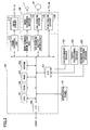
- the control device 100 includes a CPU 101, a ROM 102, a RAM 103, a nonvolatile memory (NVRAM) 104, an interface (I/F) 106, an input-output port (I/O) 107, a head control unit 111, a main scanning motor driving unit 113, a sub-scanning motor driving unit 115, a head driver 117, and the like.
- NVRAM nonvolatile memory
- I/F input-output port
- the driving system 120 includes a main scanning motor 121, a sub-scanning motor 123, a high-tension circuit 125, and the like.
- the paper feed tray 4 is disposed at a lower end portion of a body of the ink-jet recording apparatus and is capable of loading multiple sheets of paper 3.
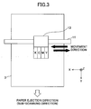
- the carriage 13 is held slidably in the X axis direction by two guide shafts 11 and 12 extending in the X axis direction. Further, the guide shaft 11 is rotatably driven by the main scanning motor 121. Accordingly, when the guide shaft 11 is rotatably driven by the main scanning motor 121, the carriage 13 is moved in the X axis direction as shown in FIG. 3, for example.
- the recording head 14 and the ink cartridge 15 are installed on the carriage 13, so that when the carriage 13 is moved in the X axis direction, the recording head 14 and the ink cartridge 15 are also moved in the X axis direction.
- the recording head 14 includes four ink-jet heads (Hk, Hc, Hm, and Hy) in which plural discharge nozzle holes for discharging ink droplets in a -Z direction are arranged and formed.
- the ink-jet head Hk is for black (K) ink
- the ink-jet head Hc is for cyan (C) ink
- the ink-jet head Hm is for magenta (M) ink
- the ink-jet head Hy is for yellow (Y) ink.
- order of the ink-jet heads is not limited to FIG. 4A and the ink-jet heads may be integrated as shown in FIG. 4C, for example.
- the recording head 14 also includes an energy generation mechanism for discharging ink.
- Examples that may be used for the energy generation mechanism include a piezoelectric actuator using a piezoelectric effect with the use of a piezoelectric element, a thermal actuator using a phase change from film boiling of liquid with the use of an electrothermal element such as a heat element, a shape memory actuator using a metallic phase change from a thermal change with the use of a shape memory alloy, an electrostatic, actuator using electrostatic force, and the like.
- the energy generation mechanism is driven through a driving signal from the head driver 117.
- pressure energy is generated by steeply reducing a capacity of a liquid chamber filled with ink using the piezoelectric element, so that the ink is discharged from the nozzle due to the pressure energy.
- thermal energy is applied to the ink from the electrothermal element, so that air bubbles are generated in the ink due to the thermal energy and the ink is discharged from the nozzle.
- the ink cartridge 15 includes a black ink cartridge, a cyan ink cartridge, a magenta ink cartridge, and a yellow ink cartridge, and supplies each ink to the recording head 14.
- a sub-tank may be installed so that the ink is filled or supplied from a main tank to the sub-tank.
- the ink cartridge 15 is detachable from the carriage 13.
- the paper feed runner 21 is disposed on a +Z side relative to the paper feed tray; 4.
- the paper 3 on top of the plural paper 3 on the +Z side loaded on the paper feed tray 4 is brought into contact with the paper feed runner 21 and sent to the conveying guide unit 23 through an up-down mechanism (not shown in the drawings).
- the conveying guide unit 23 is disposed on a - Y side relative to the paper feed runner 21.
- the conveying guide unit 23 guides the paper 3 upward (+Z direction) along a guide surface 23a after the paper 3 is taken out from the paper feed tray 4 by the paper feed runner 21.
- the conveying guide unit 23 guides the paper 3 upward (+Z direction) along a guide surface 23b after the paper 3 is reversed in the duplex unit 7 disposed on the -Y side relative to the conveying guide unit 23.
- the conveying roller 24 and the pressurizing runner 25 are disposed on the +Z side relative to the conveying guide unit 23. While the paper 3 from the conveying guide unit 23 is pressed on the conveying roller 24 by the pressurizing runner 25, the paper 3 is moved in the +Z direction in accordance with rotation of the conveying roller 24.
- the conveying roller 24 is configured to be rotated substantially at the same time as when the ink-jet recording apparatus 1 is powered on.
- the guide member 26, the guide member 27, and the pressing runner 28 are disposed on the +Z side relative to the conveying guide unit 23.
- the guide member 26 changes a movement direction of the paper 3 from the +Z direction to a +Y direction.
- the guide member 27 guides the paper 3 such that the paper 3 returned for duplex printing is directed toward the duplex unit 7.
- the pressing runner 28 presses the paper 3 whose movement direction is changed to the +Y direction by the guide member 26 and the paper 3 returned from the conveying belt 33 for duplex printing on the conveying roller 24.
- the conveying belt 33 is an endless annular member.
- the conveying belt 33 is wound on the driving roller 31 and the driven roller 32 and disposed on a +Y side relative to the conveying guide unit 23 and a -Z side relative to the recording head 14.
- the paper 3 pressed on the conveying roller 24 by the pressing runner 28 is transferred from the conveying roller 24 to the conveying belt 33 in accordance with the rotation of the conveying roller 24.
- the conveying belt 33 has a double-layered structure made of a surface layer 33a and a rear layer 33b.
- both surface layer 33a and rear layer 33b are formed using a pure resin material (ETFE pure material, for example) having a thickness of about 40 ⁇ m.
- EFE pure material for example
- resistance is not controlled on a surface (face to which the paper 3 is attracted) of the surface layer 33a
- resistance is controlled using carbon on a surface (face brought into contact with the driving roller 31 and the driven roller 32) of the rear layer 33b.
- the rear layer 33b is also referred to as a middle resistive layer or an earth layer.
- the driving roller 31 is configured to be rotated in the counterclockwise direction by the sub-scanning motor 123.
- the conveying belt 33 is rotated in the counterclockwise direction.
- the charging roller 34 is disposed such that it is brought into contact with the surface layer 33a of the conveying belt 33 and rotated in accordance with the rotation of the conveying belt 33. Further, the charging roller 34 is supplied with a high voltage from the high-tension circuit 125. Accordingly, when the high voltage is applied to the charging roller 34, the conveying belt 33 is charged.
- the guide roller 35 is disposed on a position facing the charging roller 34 across the conveying belt 33 and presses the conveying belt 33 on the charging roller 34.
- the paper ejection roller 38 is disposed on the +Y side relative to the conveying belt 33 and sends the paper 3 to the paper ejection tray 6.
- the paper ejection roller 38 is configured to be rotated substantially at the same time as when the ink-jet recording apparatus 1 is powered on. Residual ink attached to the conveying belt 33 is removed by a cleaning roller (not shown in the drawings).
- the duplex unit 7 is disposed on the -Y side relative to the conveying mechanism 5 and used upon performing duplex printing on the paper 3.
- the paper 3 after printing on one face (surface) is performed is conveyed in the opposite direction (-Y direction in this case) by the conveying mechanism 5, guided by the guide member 27, and taken in the duplex unit 7.
- the paper 3 is conveyed to the conveying roller 24 along the guide surface 23b and transferred to the conveying belt 33.
- the I/F 106 is a bidirectional communication interface with a host (external devices including information processing devices such as personal computers (hereafter referred to as "PC"), image reading devices such as image scanners, imaging devices such as digital cameras, and the like).
- Print data including image data is input from the host via the I/F 106.
- a form of connection with the host may be wireless connection using infrared or the like in addition to cable connection using a communication line such as a communication cable (USB cable, for example).
- the I/F 106 may be connected to the host via a LAN or a network such as the Internet.
- the ROM 102 stores various types of programs including a program according to the present invention written in a code decodable in the CPU 101, various types of fixed data (font data, for example) necessary for there programs, and the like.
- the RAM 103 is a working memory in which print data from the host, dot pattern data described later, and the like are temporarily stored.
- the NVRAM 104 is capable of holding data even when the control device 100 is powered off.
- the NVRAM 104 stores data repeatedly used and the like.
- the I/O 107 has a parallel port for signal input and a parallel port for signal output.
- the parallel port for signal input includes the above-mentioned environment sensor 133, the paper positioning sensor 135, the recording head positioning sensor 137, and the like connected thereto.
- the environment sensor 133 measures temperature and humidity in the vicinity of the recording head 14, the paper positioning sensor 135 detects a position of the paper 3 on the conveying belt 33, and the recording head positioning sensor 137 detects a;position of the recording head 14 in the main scanning direction.
- Information on the paper position from the paper positioning sensor 135 is notified to the CPU 101 and the sub-scanning motor driving unit 115. Further, information on the recording head position from the recording head positioning sensor 137 is notified top the CPU 101, the sub-scanning motor driving unit 115, and the main scanning motor driving unit 113.
- the head control unit 111 includes a ROM storing data on various types of driving waveforms (driving signals), a waveform generation circuit including a D/A converter for converting the data on driving waveforms read out from the ROM from digital to analog, a driving waveform generation circuit including an amplifier for amplifying output signals of the waveform generation circuit, and the like (none of them is shown in the drawings).
- the data on various types of driving waveforms may be stored in the ROM 102.
- the head control unit 111 Upon recording, the head control unit 111 takes out dot pattern data corresponding to a single row from the RAM 103, converts the dot pattern data for a single row to serial data, and transmits the converted data to the head driver 117 in synchronization with a clock signal. Further, the head control unit 111 transmits a latch signal to the head driver 117 at predetermined time.
- the head driver 117 includes a shift register to which the clock signal and the serial data from the head control unit 111 is input, a latch circuit for latching register values from the shift register using the latch signal from the head control unit 111, a level conversion circuit (level shifter) for changing levels of output values of the latch circuit, and an analog switch array in which on/off control is made in accordance with an output signal of the level shifter.
- a predetermined driving waveform is applied to the energy generation mechanism of the recording head 14.
- the main scanning motor driving unit 113 generates a driving signal for driving the main scanning motor 121.
- the driving signal generated in the main scanning motor driving unit 113 is output to the main scanning motor 121.
- the main scanning motor driving unit 113 drives the main scanning motor 121 while referring to the above-mentioned recording head position information and moves the recording head 14 to a recording start position in the main scanning direction.
- the main scanning motor driving unit 113 drives the main scanning motor 121 in synchronization with the clock signal form the head control unit 111. In this case, recording is performed in both going route and returning route of the recording head 14.
- the sub-scanning motor driving unit 115 generates a driving signal for driving the sub-scanning motor 123.
- the driving signal generated in the sub-scanning motor driving unit 115 is output to the sub-scanning motor 123.
- the sub-scanning motor driving unit 115 refers to the above-mentioned paper position information.
- the sub-scanning motor driving unit 115 confirms that the paper 3 has achieved a predetermined position on the conveying belt 33
- the sub-scanning motor driving unit 115 temporarily stops the sub-scanning motor 123.
- the sub-scanning motor driving unit 115 controls the sub-scanning motor 123 while referring to the above-mentioned recording head position information and the paper position information. In other words, when recording for a single row is finished, the sub-scanning motor driving unit 115 controls the sub-scanning motor 123 such that the next row is a recording position of the recording head 14.
- the CPU 101 controls an entire portion of the ink-jet recording apparatus 1 in accordance with the program stored in the ROM 102.
- the control device 100 includes the operation panel 131 connected thereto.
- the operation panel 131 has a display device and an input device.
- the control device 100 includes the high-tension circuit 125 connected thereto.
- the CPU 101 selects one of a status where a positive high voltage is applied to the charging roller 34 (hereafter referred to as a "positive voltage application status"), a status where a negative high voltage is applied to the charging roller 34 (hereafter referred to as a "negative voltage application status”), and a status where no high voltage is applied to the charging roller 34 (hereafter referred to as an "off status").
- a dither mask has been conventionally used in which a diagonal line base with an angle of 45 degrees is used, continuity of tone is maintained in all tones, and high-pass filter characteristics are provided taking into consideration characteristics of human sight.
- a unit mask of a diagonal line base as shown in FIG. 6 will be described. Although the unit mask has a base line repeated in every five dots, the size may be 4 ⁇ 4, 3 ⁇ 3, or larger than these sizes.
- tones are expressed by gradually thickening the base line of the unit mask.
- three types of diameter of ink droplet namely, large droplet/medium droplet/small droplet are used.
- the number of tones is limited. For example, in order to express 256 tones in two values (dot/blank), at least 16 ⁇ 16 mask size is necessary. In order to express 256 tones in four values (blank/small droplet/medium droplet/large droplet), at least 8 ⁇ 8 mask size is necessary.
- a dither mask (also referred to as a threshold mask) of 5n ⁇ 5n (n: arbitrary integer) is used in practice where the 5 ⁇ 5 unit mask is used as a minimum unit and the mask size is further enlarged.
- the tones are expressed by determining an arrangement of dots (hereafter referred to as "discharged dots" for convenience sake) in which ink is dispersedly discharged.
- FIG. 7-(a) to FIG. 7-(1) show tones when the base pattern is most emphasized among all tones that can be expressed.
- tones are expressed by gradually increasing the discharged dots on the base line.
- the base pattern is emphasized by preferentially arranging discharged dots of small droplets at positions with an angle of 45 degrees in the minimum 5 ⁇ 5 unit.
- the base pattern is emphasized by preferentially arranging discharged dots of medium droplets at positions with the angle of 45 degrees in the minimum 5 ⁇ 5 unit.
- FIG. 7-(a) to FIG. 7-(1) show tones when the base pattern is most emphasized among all tones that can be expressed.
- tones are expressed by gradually increasing the discharged dots on the base line.
- the base pattern is emphasized by preferentially arranging discharged dots of small droplets at positions with an angle of 45 degrees in the minimum 5 ⁇ 5 unit.
- the base pattern is emphasized by preferentially arranging discharged dots of medium droplets at positions with the angle of 45 degrees in the minimum 5 ⁇ 5
- the base pattern is thickened by preferentially arranging the discharged dots of small droplets on both sides of the base line. Higher tones are expressed in the same manner.
- the arrangement of discharged dots for emphasizing the base as shown in FIG. 7-(a) to FIG. 7-(i) is referred to a "base pattern".
- FIG. 11-(a) shows an example of a dot pattern when shifting from the base pattern of FIG. 7-(b) to the base pattern of FIG. 7-(c).
- FIG. 11-(b) shows a dot pattern in which the base line is removed from FIG. 11-(a). This shows the high-pass filter characteristics.
- FIG. 12 is a diagram showing an example of gradation when an image is recorded using the dither mask generated as mentioned above. This dot pattern is advantageous in that the continuity of tone is maintained in all tones and that banding and the like are unlikely to be noticeable.
- ink droplets may be discharged onto positions shifted from object positions.
- granularity (roughness) of the image may be deteriorated or the base line may not formed, so that image quality could be degraded.
- the ink droplets may be discharged at positions shifted from the object positions (refer to FIG. 13-(b)).
- ink may be partially overlapped or mixed as shown in FIG 13-(c), for example.
- a CMM (Color Management Module) process is performed on image data specified by the user.
- the image data is converted from a color space for monitor display (RGB color system) to a color space for image recording apparatuses (CMY color system).
- a BG/UCR (black generation/Under Color Removal) process is performed on the image data subjected to the CMM process.
- black generation/under color removal is performed on CMY values.
- ⁇ correction is preformed on the image data subjected to the CMM process.
- the ⁇ correction is performed in accordance with characteristics of the ink-jet recording apparatus 1 and an instruction by the user.
- the image data subjected to the ⁇ correction is output to the ink-jet recording apparatus 1 as print data.
- a starting address of a program corresponding to a flowchart of FIG. 15 stored in the ROM 102 is set in a program counter of the CPU 101 and a process (recording process) is started.
- flowcharts of FIGS. 15 and 16 correspond to a series of processing algorithm performed by the CPU 101.
- the print data from the host PC is stored in the RAM 103.
- a request for taking out paper is output to the up-down mechanism (not shown in the drawings) and the sub-scanning motor driving unit 115.
- the paper 3 is taken out from the paper feed tray 4 and is sent to the conveying mechanism 5.
- the high-tension circuit 12.5 is set to the positive voltage application status.
- the conveying belt 33 is positively charged so as to attract the paper 3 to the conveying belt 33.
- a zooming process is performed on the print data stored in the RAM 103.
- zooming is performed in accordance with resolution of the ink-jet recording apparatus 1.
- step 507 a halftone process is performed and the print data is converted to dot pattern data for each ink to be discharged from the recording head 14.
- processing step 551, step 553 shown in the flowchart of FIG. 16 is performed.
- the base pattern is determined.
- a dither process method in which the tone continuity is maintained in all tones based on the diagonal line base is used so as to express halftones, for example.
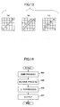
- the base pattern is determined such that at least one dot to which ink is not discharged (hereafter also referred to as a "undischarged dot" for convenience sake) is present between the discharged dots as shown in FIG. 17-(b) to FIG. 17-(d).
- the medium droplets are used as shown in FIG. 17-(c), so that at least one undischarged dot is present between the discharged dots.
- the halftone process for determining whether to place an ink droplet on each dot includes a dither method and an error diffusion method as will be described later.
- step 553 a complement process is performed on the determined base patterns. Density in the determined base patterns is measured and complemented such that characteristics of the density of tones between the patterns form a linear shape. Then, the halftone process is ended and the process proceeds to step 509.
- step 509 a rasterization process is performed.
- dot pattern data is divided into sets of data on a single row and the data is extracted in accordance with each nozzle position for recording.
- the extracted dot pattern data is stored in the RAM 103.
- step 511 whether the paper 3 on the conveying belt 33 is positioned at a recording start position is judged based on the paper position information.
- the judgment is affirmed and the process proceeds to step 513.
- the sub-scanning motor 123 is stopped by the sub-scanning motor driving unit 115.
- a recording start is notified to each element of the control device 100. In accordance with this, ink is discharged from the recording head 14 via the head control unit 111 and the head driver 117.
- step 515 whether recording of all the print data requested from the host is ended is judged.
- the judgment is denied and the process proceeds to step 517.
- step 517 whether printing is performed up to a last print line of one sheet of the paper 3 determined in advance by the user is judged referring to the paper position information.
- the judgment is denied and the process returns to step 515.
- the printing on the paper 3 continues while the head control unit 111, the main scanning motor driving unit 113, and the sub-scanning motor driving unit 115 operate in cooperation with one another until the judgment in step 515 or step 517 is affirmed.
- printing for a single row is performed on the stationary paper 3 while the head control unit 111 is moved in the main scanning direction and when the printing for a single row is ended, the paper 3 is moved as much as a single row in the sub-scanning direction (+Y direction in this case) and printing for the next row is performed.
- step 517 When the judgment in step 517 is affirmed before the judgment in step 515 is affirmed, the process proceeds to step 519.
- step 519 the high-tension circuit 125 is set to the negative voltage application status. In accordance with this, the conveying belt 33 is negatively charged and the electrostatic attraction of the paper 3 is released.
- step 521 whether the paper 3 is ejected from the conveying belt 33 is judged referring to the paper position information.
- the process awaits until the paper 3 is ejected.
- the judgment is affirmed and the process proceeds to step 523.
- step 523 a request for taking out paper is output to the above-mentioned up-down mechanism (not shown in the' drawings) and the sub-scanning motor driving unit 115. In accordance with this, a new paper 3 is taken out from the paper feed tray 4 and sent to the conveying mechanism 5.
- step 525 the high-tension circuit 125 is set to the positive voltage application status. In accordance with this, the conveying belt 33 is positively charged. And the process returns to the above-mentioned step 511.
- step 515 when the recording of all the print data requested from the host is ended, the judgment in step 515 is affirmed and the process proceeds to step 527.
- step 527 the high-tension circuit 125 is set to the negative voltage application status. In accordance with this, the conveying belt 33 is negatively charged and the electrostatic attraction of the paper 3 is released.
- step 529 completion of the recording of print data is notified to the host. And the recording process is ended.
- FIG. 19 is a diagram showing images resulting from bidirectional printing of a halftone portion with a single path, no interlace, and the use of only black ink.
- FIG. 19-(a) shows a result of a going route
- FIG. 19-(b) shows a result of a returning route.
- FIG. 20-(a) shows a result of bidirectional printing of the going route according to the conventional halftone process.
- FIG. 20-(b) shows a result of bidirectional printing of the returning route according to the conventional halftone process.
- FIG. 20-(a) shows mixed adjacent droplets.
- FIG. 19-(a) shows an improved result.
- a difference between the going route and the returning route is reduced in comparison with the conventional halftone process.
- a difference of lightness between the going route and returning route is 1.8.
- the difference of lightness between the going route and returning route is 0.62.
- a difference of density between the going route and returning route is 0.026.
- the difference of density between the going route and returning route is 0.009.
- the present embodiment is capable of performing preferable recording even when the landing accuracy is low.
- the dither method is described as a halftone process method for determining whether to discharge an ink droplet onto each dot.
- the dither method is for obtaining N values (N ⁇ 2) by comparing an original image with thresholds arranged in a rectangular (matrix) area and the dither method is capable of generating an N-valued image relatively speedy.
- M ⁇ M pixels are used as a unit for expressing tones and a matrix of M ⁇ M thresholds is created for the unit.
- the threshold matrix is referred to as a "dither mask”.
- the dither mask is superposed on the original image and the density of each pixel is compared with that of a corresponding threshold. When the density is larger than the threshold, an ink dot is attached to the pixel.
- FIG. 22 is a diagram showing size of dots (ink droplets) in a case where N - four values.
- N four values
- four types of dots are set including no dot where no dot (ink droplet) is placed, a small dot using a small droplet, a medium dot using a medium droplet, and a large dot using a large droplet as shown in FIG. 22.
- N four values in line base dithering (1/5 base), namely, when large droplets are placed on all dot areas, dots in each dot area are grown as shown in FIG. 23-(a) to 23-(1), for example. Positions of dots to be formed are determined so as to be remote from previously formed dots as much as possible.
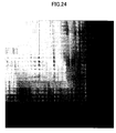
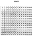
- FIG. 25 is a diagram showing numerical values in a matrix indicating the density of the original image shown in FIG. 24.
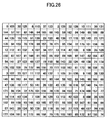
- FIG. 26 is a diagram showing an example of a dither mask in a case of two values.
- FIG. 27 is a diagram showing an output image through the dither mask of FIG. 26.
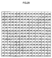
- FIGS. 28 to 30 are diagrams showing examples of dither masks in the case of four values.
- FIG. 28 shows a dither mask for large droplets.
- FIG. 29 shows a dither mask for medium droplets.
- FIG. 30 shows a dither mask for small droplets.
- FIG. 31 is a diagram showing an output image through the dither masks of FIGS. 28 to 30.
- a value of "999" is used as dummy data so as to forcibly control generation of dots.
- the value of dummy data is not limited to "999” and other value may be used as long as such a value exceeds "255" indicating a maximum value of density.
- N two values
- the original image and the dither mask are compared and ink is attached to pixels exceeding the thresholds of dither mask.
- a numeral value of "10” is designated to a third dot from left and a first dot from top in FIG. 25 indicating the density of the original image and a numeral value of "30” is designated to the same position in FIG. 26.
- This dot position is referred to as (3, 1) in coordinates.
- the value "10" indicating the density in the original image is less than a threshold "30" in the dither mask, so that no ink droplet is attached.
- large droplets are attached.
- the original image and the dither mask for medium droplets shown in FIG. 29 are compared.
- the numeral values in the original image are larger than the numeral values in the dither mask, medium droplets are attached.
- the numeral values in the original image are smaller than the numeral values in the dither mask, the original image and the dither mask for small droplets shown in FIG.
- a numeral value in the original image shown in FIG. 25 is "200” and a numeral value in the dither mask for large droplets shown in FIG. 30 is "244", so that a large droplet is not attached and the numeral value "200" is compared with the dither mask for medium droplets shown in FIG. 29.
- a corresponding numeral value in the dither mask for medium droplets is "197” and the numeral value "200" in the original image exceeds the numeral value in the dither mask, so that a medium droplet is attached.
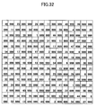
- FIG. 32 is a diagram showing an example of a dither mask obtained by employing the present invention.
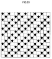
- FIG. 33 is a diagram showing an output image through the dither mask shown in FIG. 32.
- dots are not generated at adjacent dot positions by using the dummy data "999" as shown in FIG. 32.
- the density of dots of the image does not exceed a threshold of "999" and ink droplets are not placed at these positions, so that no ink droplet is placed in adjacent dot areas.
- dither process methods include what is called bayer dithering.
- 0 8 2 10 12 4 14 6 3 11 1 9 15 7 13 5
- FIG. 34 is a matrix showing the above-mentioned bayer dither mask D 4 .
- FIG. 35-(a) to FIG. 35-(p) show how dots are placed through comparison with the thresholds in FIG. 34.
- a threshold is a minimum value of "0" and a first dot is placed at coordinates (1, 1) as shown in FIG. 35-(a).
- a second smallest number is "1" at coordinates (3, 3) and a dot is placed at coordinates (3, 3) as shown in FIG. 35-(b).
- a third smallest number is "2" at coordinates (3, 1) and a dot is placed at coordinates (3, 1) as shown in FIG. 35-(c).
- FIG. 35-(d) to FIG. 35-(p) dots are placed in ascending order of thresholds, so that the dots are arranged so as to be remote from one another as much as possible.
- tones are set such that at least one dot to which ink is not discharged is present between dots to which ink is discharged upon performing the halftone process on the print data.
- it is possible to prevent adjacent ink droplets on paper from becoming mixed even when the landing accuracy is low.
- it is possible to record high-quality images without causing an increase of cost or a reduced recording speed. In other words, it is possible to compensate for a poor landing accuracy.
- a space between the recording head 14 and the conveying belt 33 (namely, a space between the recording head 14 and the paper 3) is adjusted to be wider in comparison with printing on normal paper. Accordingly, even when the landing accuracy for printing on normal paper satisfies standards set in advance, landing positions for printing on envelopes, cardboard, or the like may be uneven, so that the landing accuracy could not satisfy the standards.
- the above-mentioned halftone process may be performed when printing objects are envelopes, cardboard, or the like and a conventional halftone process is performed when the printing object is normal paper.
- output of the environment sensor 133 may be monitored, so that the above-mentioned halftone process may be performed when at least one of the temperature and humidity exceeds the threshold.
- the conveying belt 33 has a double-layered structure.
- the present invention is not limited to this and the structure may have a single layer or more than two layers.
- the recording head 14 has ink-jet heads for four colors, namely, black (K), cyan (C), magenta (M), and yellow (Y).
- the present invention is not limited to this.
- the recording head 14 may have ink-jet heads for six colors including light cyan (LC) and light magenta (LM) with reduced density in addition to the four colors.
- the recording head 14 may have ink-jet heads for seven colors including dark yellow (DY) with reduced chroma in addition to the six colors.
- the recording head 14 may have ink-jet heads including a specific color such as red (R), blue (B) or the like.
- the halftone process is performed on print data of all of the four colors, it is possible to perform the halftone process according to the present embodiment on one to three colors having a great influence on recording quality by selecting from the four colors.
- a conventional halftone process may be performed on print data of the other colors having little influence on the recording quality.
- the programs relating to the present invention are recorded in the ROM 102
- the programs may be recorded in other recording media (CD, magneto-optical disk, DVD, memory card, USB memory, flexible disk, and the like).
- the programs relating to the present invention are loaded into the above-mentioned NVRAM 104 or a main memory not shown in the drawings via a reproducing device (or a dedicated interface) for each recording medium.
- the programs relating to the present invention may be loaded into the NVRAM 104 or the main memory (not shown in the drawings) via a network (LAN, intranet, Internet, or the like).
- zooming process may be performed on the host PC side.
- the ink-jet recording apparatuses may experience reduced landing accuracy due to secular change even if the landing accuracy is high upon product shipment.
- presence or absence of abnormality in the landing accuracy may be checked and the above-mentioned halftone process may be performed when abnormality in the landing accuracy is detected.
- the CPU 101 may perform the above-mentioned halftone process when "abnormal landing accuracy" is input from the measurement device.
- the presence or absence of abnormality in the landing accuracy may be checked by examining whether a color difference is generated between recording in a going route and recording in a returning route through visual observation or a predetermined measurement device by the user.
- the result may be input form the operation panel 131 and the CPU 101 may perform the halftone process according to the above-mentioned embodiment when "abnormal landing accuracy" is input.
- the halftone process according to the above-mentioned embodiment may be performed when print data is recorded in the recording modes showing abnormality in the landing accuracy.
- the user may input the presence or absence of abnormality from the operation panel 131 following a comparison of a test image recorded in a conventional halftone process with a sample image having an ideal landing through visual observation or a predetermined measurement device by the user.
- the CPU 101 may perform the halftone process according to the above-mentioned embodiment when "abnormal landing accuracy" is input.
- one of the halftone process according to the above-mentioned embodiment and a conventional halftone process may be selected.
- the user notifies selection to the CPU 101 via the operation panel 131.
- the dithering according to the above-mentioned embodiment may be automatically generated or downloaded via a network or the like.
- the dither process is used so as to express halftones.
- the present invention is not limited to this.
- an error diffusion method may be used so as to express halftones.
- FIG. 39 is a flowchart showing an algorithm in this case.
- ink is placed on a certain dot A when a value in which an error obtained from peripheral dots of dot A is added to a tone value of dot A exceeds a predetermined threshold.
- a value in which an error obtained from peripheral dots of dot A is added to a tone value of dot A exceeds a predetermined threshold When the value does not exceed the threshold, ink is not placed.
- dot B adjacent to dot A in which whether to place ink is determined prior to dot A when ink is placed on dot B (Y in step 603), calculation for comparison with the threshold is not performed so as not to place ink on dot A, so that ink is not placed on dot A regardless of the tone value, threshold, and error value (step 605).
- a normal error diffusion process is performed (step 607). In accordance with this, when the landing accuracy is abnormal, ink is not successively placed on adjacent dots in the same manner as in the above-mentioned embodiment, so that it is possible to obtain the same effect as in the above-menti
- each ink-jet head of the recording head 14 includes plural discharged nozzle holes.
- the present invention is not limited to this.
- Each ink-jet head may have a single discharge nozzle.
- the setting method according to the present invention is suitable for preventing adjacent ink droplets from becoming mixed even when the landing accuracy of ink droplets is low.
- the image recording apparatus according to the present invention is suitable for recording high-quality images without causing an increase of cost or a reduced recording speed.
- the program and recording medium according to the present invention are suitable for causing the image recording apparatus to record high-quality images without causing an increase of cost or a reduced recording speed.
Landscapes
- Engineering & Computer Science (AREA)
- Quality & Reliability (AREA)
- Multimedia (AREA)
- Signal Processing (AREA)
- Ink Jet (AREA)
- Particle Formation And Scattering Control In Inkjet Printers (AREA)
- Color, Gradation (AREA)
Applications Claiming Priority (2)
| Application Number | Priority Date | Filing Date | Title |
|---|---|---|---|
| JP2006070099 | 2006-03-15 | ||
| JP2007035524A JP2007276449A (ja) | 2006-03-15 | 2007-02-15 | 設定方法、画像記録装置、プログラム及び記録媒体 |
Publications (1)
| Publication Number | Publication Date |
|---|---|
| EP1835722A1 true EP1835722A1 (de) | 2007-09-19 |
Family
ID=38117450
Family Applications (1)
| Application Number | Title | Priority Date | Filing Date |
|---|---|---|---|
| EP07251108A Ceased EP1835722A1 (de) | 2006-03-15 | 2007-03-15 | Einstellungsverfahren, Bildaufzeichnungsgerät, Programm und Aufzeichnungsmedium |
Country Status (4)
| Country | Link |
|---|---|
| US (1) | US8363279B2 (de) |
| EP (1) | EP1835722A1 (de) |
| JP (1) | JP2007276449A (de) |
| CN (1) | CN101039373B (de) |
Cited By (1)
| Publication number | Priority date | Publication date | Assignee | Title |
|---|---|---|---|---|
| EP1924078A2 (de) * | 2006-11-17 | 2008-05-21 | Ricoh Company, Ltd. | Bildverarbeitungsverfahren, Programm, Aufzeichnungsmedium, Bildverarbeitungsvorrichtung und Bilderzeugungsvorrichtung |
Families Citing this family (17)
| Publication number | Priority date | Publication date | Assignee | Title |
|---|---|---|---|---|
| JP4545128B2 (ja) * | 2006-09-16 | 2010-09-15 | 株式会社リコー | 画像処理装置、プログラム、画像形成装置、画像形成方法、ディザマトリクス |
| US8730524B2 (en) | 2007-08-14 | 2014-05-20 | Ricoh Company, Ltd. | Image processing apparatus to correct an image during double-sided printing |
| JP5228410B2 (ja) * | 2007-09-04 | 2013-07-03 | 株式会社リコー | 画像形成方法、画像形成装置、画像形成システム、及び画像形成プログラム |
| JP2009154499A (ja) * | 2007-12-28 | 2009-07-16 | Ricoh Co Ltd | 画像形成方法、及びインクジェット記録装置 |
| JP2009184190A (ja) * | 2008-02-05 | 2009-08-20 | Ricoh Co Ltd | 画像形成方法、これを実行するプログラム、画像処理装置、画像形成装置、及び画像形成システム |
| JP4776646B2 (ja) * | 2008-03-10 | 2011-09-21 | 株式会社リコー | 画像処理装置、画像処理方法、プログラムおよび記録媒体 |
| JP2009269321A (ja) * | 2008-05-08 | 2009-11-19 | Ricoh Co Ltd | 画像処理方法、プログラム、記憶媒体、画像処理装置、画像形成装置 |
| JP2011116096A (ja) * | 2009-01-16 | 2011-06-16 | Ricoh Co Ltd | 画像形成装置、画像形成方法、及びプログラム |
| JP5625332B2 (ja) * | 2009-01-16 | 2014-11-19 | 株式会社リコー | 画像形成方法、画像形成装置、及びプログラム |
| JP5651948B2 (ja) * | 2009-02-16 | 2015-01-14 | 株式会社リコー | 画像形成方法、画像形成装置および画像形成プログラム |
| JP5511231B2 (ja) * | 2009-06-15 | 2014-06-04 | キヤノン株式会社 | 画像読取装置及び該装置の制御方法 |
| JP5772369B2 (ja) * | 2010-09-16 | 2015-09-02 | 株式会社リコー | 画像形成装置、色重ね位置ズレの補正方法、その方法をコンピュータに実行させるプログラム、およびコンピュータ読み取り可能な記録媒体 |
| CN102214434B (zh) * | 2010-09-30 | 2013-10-30 | 四川虹欧显示器件有限公司 | 图像处理方法及装置 |
| JP5824942B2 (ja) * | 2011-07-27 | 2015-12-02 | ブラザー工業株式会社 | ディザマトリクス作成装置及びディザマトリクス作成プログラム |
| JP5984416B2 (ja) * | 2012-02-10 | 2016-09-06 | キヤノン株式会社 | 画像形成装置 |
| JP6119280B2 (ja) * | 2013-02-08 | 2017-04-26 | 株式会社リコー | ディザマトリクス生成方法、画像処理方法、画像処理装置およびプログラム |
| JP6682767B2 (ja) | 2015-03-23 | 2020-04-15 | 株式会社リコー | 情報処理装置、情報処理方法、プログラムおよびシステム |
Citations (12)
| Publication number | Priority date | Publication date | Assignee | Title |
|---|---|---|---|---|
| JPS6411836A (en) * | 1987-07-06 | 1989-01-17 | Canon Kk | Method of recording color gradation |
| US4972270A (en) * | 1989-04-17 | 1990-11-20 | Stephen Kurtin | Facsimile recorder with acutely mounted staggered array ink jet printhead |
| US5237344A (en) * | 1987-11-05 | 1993-08-17 | Canon Kabushiki Kaisha | Ink jet recording apparatus and method with dot thinning |
| US5258850A (en) * | 1992-06-05 | 1993-11-02 | Eastman Kodak Company | Line screen design for gray scale rendering |
| US5821968A (en) * | 1993-07-28 | 1998-10-13 | Canon Kabushiki Kaisha | Ink jet recording apparatus and a process of ink jet recording |
| US6012797A (en) * | 1991-03-29 | 2000-01-11 | Canon Kabushiki Kaisha | Method for driving an ink jet recording head having improved discharge stability and recording apparatus having the same |
| EP1078771A2 (de) * | 1999-08-24 | 2001-02-28 | Canon Kabushiki Kaisha | Verfahren zum Einstellen der Druckpositionen, Druckgerät und Drucksystem |
| US20020024548A1 (en) * | 1993-12-28 | 2002-02-28 | Fumihiro Gotoh | Gray scale pattern and recording method and recording apparatus employing the gray scale pattern |
| US20040032446A1 (en) | 2002-08-13 | 2004-02-19 | Canon Kabushiki Kaisha | Printing apparatus and test pattern printing method |
| JP2004080065A (ja) | 2002-06-21 | 2004-03-11 | Ricoh Co Ltd | 階調再現方法、閾値マトリクス、画像処理方法、画像処理装置、画像形成装置及びプリンタドライバ |
| US6906825B1 (en) | 1999-06-14 | 2005-06-14 | Toshiba Tec Kabushiki Kaisha | Image processor and color image processor |
| US20060007494A1 (en) | 2004-07-12 | 2006-01-12 | Seiko Epson Corporation | Image processing device and dot data generation method |
Family Cites Families (22)
| Publication number | Priority date | Publication date | Assignee | Title |
|---|---|---|---|---|
| GB2182288B (en) | 1985-11-01 | 1990-09-19 | Ricoh Kk | Printing device |
| US4990939A (en) | 1988-09-01 | 1991-02-05 | Ricoh Company, Ltd. | Bubble jet printer head with improved operational speed |
| JP2836749B2 (ja) | 1989-05-09 | 1998-12-14 | 株式会社リコー | 液体噴射記録ヘッド |
| US5600356A (en) | 1989-07-25 | 1997-02-04 | Ricoh Company, Ltd. | Liquid jet recording head having improved radiator member |
| US5412413A (en) | 1989-12-22 | 1995-05-02 | Ricoh Co., Ltd. | Method and apparatus for making liquid drop fly to form image by generating bubble in liquid |
| JPH0564889A (ja) | 1990-12-14 | 1993-03-19 | Ricoh Co Ltd | インク飛翔記録方法及び装置及び該装置の製作方法 |
| JP3054450B2 (ja) | 1991-02-13 | 2000-06-19 | 株式会社リコー | 液体噴射記録ヘッド用基体及び液体噴射記録ヘッド |
| JP3311408B2 (ja) | 1992-04-20 | 2002-08-05 | 株式会社リコー | 画像形成方法及び画像形成装置 |
| JPH1075375A (ja) | 1996-05-20 | 1998-03-17 | Fuji Xerox Co Ltd | 画像処理装置、画像処理システムおよび画像処理用スクリーン生成方法 |
| JP4220654B2 (ja) * | 1999-06-14 | 2009-02-04 | 東芝テック株式会社 | 画像処理装置及びカラー画像処理装置 |
| JP4132585B2 (ja) * | 1999-06-14 | 2008-08-13 | 東芝テック株式会社 | 画像処理装置及びカラー画像処理装置 |
| JP4138219B2 (ja) | 1999-08-30 | 2008-08-27 | 花王株式会社 | 水系インク |
| JP3559753B2 (ja) * | 2000-07-17 | 2004-09-02 | キヤノン株式会社 | インクジェット記録装置及び前記装置の制御方法 |
| JP3934442B2 (ja) | 2001-03-16 | 2007-06-20 | 株式会社リコー | マスク作成方法、画像処理装置及びソフトウェアプログラム |
| JP2003001817A (ja) | 2001-06-20 | 2003-01-08 | Ricoh Co Ltd | ヘッド駆動装置及び画像記録装置 |
| JP3944711B2 (ja) | 2002-03-01 | 2007-07-18 | リコープリンティングシステムズ株式会社 | ディザマトリクス生成方法及びプリンタ |
| JP4027719B2 (ja) * | 2002-05-20 | 2007-12-26 | 株式会社セイコーアイ・インフォテック | カラー階調画像の階調再現装置 |
| JP2005001221A (ja) | 2003-06-11 | 2005-01-06 | Ricoh Co Ltd | 中間調処理用マスク作成方法およびインクジェット記録装置 |
| US7600842B2 (en) | 2003-08-05 | 2009-10-13 | Ricoh Company, Ltd. | Image reproducing and forming apparatus, printer driver and data processing apparatus |
| US6942308B2 (en) * | 2003-10-10 | 2005-09-13 | Hewlett-Packard Development Company, L.P. | Compensation of lateral position changes in printing |
| JP4518924B2 (ja) | 2004-11-29 | 2010-08-04 | 株式会社リコー | 画像処理方法、プリンタドライバ、画像処理装置、画像形成装置及び画像形成システム |
| JP4631492B2 (ja) * | 2005-03-24 | 2011-02-16 | 富士ゼロックス株式会社 | 画像形成装置、画像形成方法、及び画像形成プログラム |
-
2007
- 2007-02-15 JP JP2007035524A patent/JP2007276449A/ja active Pending
- 2007-03-14 US US11/724,355 patent/US8363279B2/en active Active
- 2007-03-14 CN CN2007101359628A patent/CN101039373B/zh not_active Expired - Fee Related
- 2007-03-15 EP EP07251108A patent/EP1835722A1/de not_active Ceased
Patent Citations (12)
| Publication number | Priority date | Publication date | Assignee | Title |
|---|---|---|---|---|
| JPS6411836A (en) * | 1987-07-06 | 1989-01-17 | Canon Kk | Method of recording color gradation |
| US5237344A (en) * | 1987-11-05 | 1993-08-17 | Canon Kabushiki Kaisha | Ink jet recording apparatus and method with dot thinning |
| US4972270A (en) * | 1989-04-17 | 1990-11-20 | Stephen Kurtin | Facsimile recorder with acutely mounted staggered array ink jet printhead |
| US6012797A (en) * | 1991-03-29 | 2000-01-11 | Canon Kabushiki Kaisha | Method for driving an ink jet recording head having improved discharge stability and recording apparatus having the same |
| US5258850A (en) * | 1992-06-05 | 1993-11-02 | Eastman Kodak Company | Line screen design for gray scale rendering |
| US5821968A (en) * | 1993-07-28 | 1998-10-13 | Canon Kabushiki Kaisha | Ink jet recording apparatus and a process of ink jet recording |
| US20020024548A1 (en) * | 1993-12-28 | 2002-02-28 | Fumihiro Gotoh | Gray scale pattern and recording method and recording apparatus employing the gray scale pattern |
| US6906825B1 (en) | 1999-06-14 | 2005-06-14 | Toshiba Tec Kabushiki Kaisha | Image processor and color image processor |
| EP1078771A2 (de) * | 1999-08-24 | 2001-02-28 | Canon Kabushiki Kaisha | Verfahren zum Einstellen der Druckpositionen, Druckgerät und Drucksystem |
| JP2004080065A (ja) | 2002-06-21 | 2004-03-11 | Ricoh Co Ltd | 階調再現方法、閾値マトリクス、画像処理方法、画像処理装置、画像形成装置及びプリンタドライバ |
| US20040032446A1 (en) | 2002-08-13 | 2004-02-19 | Canon Kabushiki Kaisha | Printing apparatus and test pattern printing method |
| US20060007494A1 (en) | 2004-07-12 | 2006-01-12 | Seiko Epson Corporation | Image processing device and dot data generation method |
Cited By (1)
| Publication number | Priority date | Publication date | Assignee | Title |
|---|---|---|---|---|
| EP1924078A2 (de) * | 2006-11-17 | 2008-05-21 | Ricoh Company, Ltd. | Bildverarbeitungsverfahren, Programm, Aufzeichnungsmedium, Bildverarbeitungsvorrichtung und Bilderzeugungsvorrichtung |
Also Published As
| Publication number | Publication date |
|---|---|
| JP2007276449A (ja) | 2007-10-25 |
| CN101039373A (zh) | 2007-09-19 |
| US20070216953A1 (en) | 2007-09-20 |
| CN101039373B (zh) | 2010-06-09 |
| US8363279B2 (en) | 2013-01-29 |
Similar Documents
| Publication | Publication Date | Title |
|---|---|---|
| US8363279B2 (en) | Method and device for setting multiple tones in halftone process to prevent mixing of adjacent ink dots | |
| US8626623B2 (en) | Image processing apparatus, image processing method, and recording medium | |
| EP1956522B1 (de) | Bildgebungsverfahren und Bilderzeugungsvorrichtung | |
| EP1986855B1 (de) | Bildverarbeitungsverfahren, aufgezeichnetes mittel, programm, bildverarbeitungsvorrichtung, bilderzeugungsvorrichtung, bilderzeugungssystem und tinte | |
| EP2271499B1 (de) | Bildbearbeitungsverfahren, computerprogramm, aufzeichnungsmedium, bildbearbeitungsvorrichtung und bilderzeugungsvorrichtung | |
| KR100895799B1 (ko) | 화상 재생 및 형성 장치, 프린터 드라이버 및 데이터 처리장치 | |
| US8628165B2 (en) | Image forming apparatus, image forming method, pattern forming method and recording medium | |
| US8326032B2 (en) | Image processing apparatus, image processing method, and computer program product | |
| US20110170142A1 (en) | Image processing apparatus, image processing method, program, recording medium, printing system, image forming apparatus | |
| EP1907211B1 (de) | Bildgebungsverfahren und tintenstrahlaufzeichnungsvorrichtung | |
| US20070091135A1 (en) | Image processing method, image processing apparatus, and computer-readable recording medium | |
| EP1805980B1 (de) | Bildverarbeitungsvorrichtung, bilderzeugungsvorrichtung und programm | |
| JP2013052614A (ja) | 画像処理方法、画像処理プログラム及び情報処理装置 | |
| US10469712B2 (en) | Image forming apparatus and image forming method | |
| US8243291B2 (en) | Image forming apparatus with correction device for defect correction | |
| US8434848B2 (en) | Image forming device and image forming method | |
| US8564838B2 (en) | Image processing apparatus and method for determining arrangement of dot count or recording material amount by error diffusion process | |
| JP2006173929A (ja) | 画像処理方法、プログラム、画像処理装置及び画像形成装置 | |
| JP3921965B2 (ja) | インターレース記録モードを有するプリンタにおける紙送り誤差の補正 | |
| JP3921966B2 (ja) | プリンタにおける紙送り誤差の補正 | |
| JP2010173306A (ja) | 画像処理装置、画像処理方法、プログラム及び記録媒体 | |
| JP6064523B2 (ja) | 階調処理方法、画像形成装置、及びプログラム | |
| JP2004306552A (ja) | 画像記録方法及び画像記録装置 | |
| JP2009048491A (ja) | 画像処理装置および画像処理方法 | |
| JP2011042054A (ja) | 記録装置、制御方法及びプログラム |
Legal Events
| Date | Code | Title | Description |
|---|---|---|---|
| PUAI | Public reference made under article 153(3) epc to a published international application that has entered the european phase |
Free format text: ORIGINAL CODE: 0009012 |
|
| 17P | Request for examination filed |
Effective date: 20070405 |
|
| AK | Designated contracting states |
Kind code of ref document: A1 Designated state(s): AT BE BG CH CY CZ DE DK EE ES FI FR GB GR HU IE IS IT LI LT LU LV MC MT NL PL PT RO SE SI SK TR |
|
| AX | Request for extension of the european patent |
Extension state: AL BA HR MK YU |
|
| 17Q | First examination report despatched |
Effective date: 20080320 |
|
| AKX | Designation fees paid |
Designated state(s): DE ES FR GB IT NL |
|
| STAA | Information on the status of an ep patent application or granted ep patent |
Free format text: STATUS: THE APPLICATION HAS BEEN REFUSED |
|
| 18R | Application refused |
Effective date: 20170828 |